You are using an out of date browser. It may not display this or other websites correctly.
You should upgrade or use an alternative browser.
You should upgrade or use an alternative browser.
Lower quarter patch panel advice
- Thread starter robking
- Start date
Absent any rust issues interfering, Ideally you would place the seam just below (about an inch to allow room for dolly from the back side) that bottom crease (under the orange) as this slight crown gets your weld in a nice area for planishing from the outside, and a straight cut horizontally would eliminate any of the puckers normally seen on inside corners. The red and green cuts are going through a substantial crown in the middle of the panel, which is going to pull inward and may require additional planishing to keep things where they should be. The downside to anything that pulls inward is the the most effective planishing is from a hammer strike from the inside or to a lesser extent, pushing outward with the dolly while striking from the outside. Which means limited room available the closer you get to the wheel well.
Given the rust issues present, the area below the bottom crease is too low. The next best option IMO would be to go about an inch above the crease in the concave valley. Here any shrinkage is going to pull OUTWARD so it will be easier to planish with hammer swings from the outside. This means your hammer face will need to conform to the shape of the valley without the edges of the hammer touching. (In much the same fashion as selecting a dolly, as close to the shape of the panel as possible without the edges touching as that will cause coining) I think I’ve shown the fabrication of a body hammer using a leaf spring eye (I’ll try to find a link) and this hammer is ideal in working such areas. Jim Kueneman’s current project included welding on near full quarter panels and I convinced him to use a similar feature just below the top of the quarter, so if you look at his thread you can see the concept of welding through that area.
I think the area above the crease (slightly higher than you show) through the center of the inward radius will be easier to address planishing efforts. If you need to go up into the wheel well flare any higher, I would almost do that as a separate piece as it will give you better options for planishing while the bottom of the quarter is open. Once that is done (and planished) then finish up with the horizontal seam across for the entire bottom part.
Here's a picture of the profile in that area around the lower body line (at about 5").
Here's one of the hammers I have that might work (I have a very basic set of body hammers). I also have another with less crown that matches more closely, but would definitely need to grind/smooth edges. Probably need to do that to all of them.
Here's a little more detail showing how big my AMD patch panel is. Getting in there from the back side (was hard to get a picture), I think I need to cut that lip at least 2" above the body line to have decent metal to weld to, as well as give me room to repair the lower edge of the wheel well. In a nutshell, the closer to the edge of my new panel the better.I wouldn't cut the patch panel before you find out how far the rust goes up the seam.

For reference, heres the other side with the same patch.
Absent any rust issues interfering, Ideally you would place the seam just below (about an inch to allow room for dolly from the back side) that bottom crease (under the orange) as this slight crown gets your weld in a nice area for planishing from the outside, and a straight cut horizontally would eliminate any of the puckers normally seen on inside corners. The red and green cuts are going through a substantial crown in the middle of the panel, which is going to pull inward and may require additional planishing to keep things where they should be. The downside to anything that pulls inward is the the most effective planishing is from a hammer strike from the inside or to a lesser extent, pushing outward with the dolly while striking from the outside. Which means limited room available the closer you get to the wheel well.
Given the rust issues present, the area below the bottom crease is too low. The next best option IMO would be to go about an inch above the crease in the concave valley. Here any shrinkage is going to pull OUTWARD so it will be easier to planish with hammer swings from the outside. This means your hammer face will need to conform to the shape of the valley without the edges of the hammer touching. (In much the same fashion as selecting a dolly, as close to the shape of the panel as possible without the edges touching as that will cause coining) I think I’ve shown the fabrication of a body hammer using a leaf spring eye (I’ll try to find a link) and this hammer is ideal in working such areas. Jim Kueneman’s current project included welding on near full quarter panels and I convinced him to use a similar feature just below the top of the quarter, so if you look at his thread you can see the concept of welding through that area.
I think the area above the crease (slightly higher than you show) through the center of the inward radius will be easier to address planishing efforts. If you need to go up into the wheel well flare any higher, I would almost do that as a separate piece as it will give you better options for planishing while the bottom of the quarter is open. Once that is done (and planished) then finish up with the horizontal seam across for the entire bottom part.
Sorry for being dense. Is the idea to do something like the area in red as a small patch, with the larger 2nd patch have one long horizontal top edge (along the blue marker line)?
Not sure how easy it is to tell, but the top of the hole you see here is the top of the cutout in the previous picture. I have a wedge shaped dolly that I can get in there, however its not going to have a lot of mass. Although I can probably wedge it up against the wheel well and support it that way. I can get my finger between the wheel well and the quarter to the point that the tip of my finger barely touches the lip, so they aren't flush against each other. I need to patch in about 1" to the bottom of the wheel well around that rust hole area as well. Basically the wheel well, trunk extension and quarter all come together right there, and the junk that accumulated there and stayed wet for years rotted them all out.What is the access to that area from the inside ??
MP&C
Member
It appears much of that rust stems from the “shelf” that filled the hole. If you can take your cut line up another inch and be out of the “rust belt”, your patch should have enough metal there still to allow a straight cut across. A straight seam front to back coupled with a nice even HAZ is going offer the least amount of distortion over adding corners and tabs. If you have an ice pick, it will tell you quickly if the rust extends up any further.
Use it as you would on a block of ice. If the pick goes through, the rust would have appeared in a couple years through your fresh paint. If it holds the ice pick from going through, it will hold paint. Find out how far the rust goes before making any decision to cut your replacement panel

Use it as you would on a block of ice. If the pick goes through, the rust would have appeared in a couple years through your fresh paint. If it holds the ice pick from going through, it will hold paint. Find out how far the rust goes before making any decision to cut your replacement panel
I do like the idea of a straight across cut, and going up a little more simplifies cutting through the bumper recess at the rear of the quarter. I'm pretty sure its solid that far up but will double check with my scratch awl. I think going up a little more also helps with smoothing the existing panel.
As always, the SPI forums have been a tremendous asset. Thanks again to you, Chris and the others who've chimed in!
I'll post an update with pics, hope to actually get to it next week.
As always, the SPI forums have been a tremendous asset. Thanks again to you, Chris and the others who've chimed in!
I'll post an update with pics, hope to actually get to it next week.
Please forgive the hijack but I feel this is a good place to ask for help in this matter.Robert as always offers excellent sound advice... When I say tack I mean just that. On and off. This is critical. You need to have the proper gap (.030-.035) between the panels and you need to be able to tack it quickly. On and off. Dial in your settings by practicing on some scrap of the same gauge beforehand.
I have tried this approach and can get as far as securing the panels and making the initial cut. Either because of a total lack of experience or my visual impairment I cant seem to get tacks in place without blowing holes at the cut/panel edges. I have tried starting away from the edge, at the edge, and sneaking up on the edge. I have watched countless tutorial videos, including many of "Fitzee's Fabrications" excellent explanations with no luck. Can one of the experts provide an explanation on how to correctly tack the 1/32" gap? I have an Eastwood NIG 135 and have tried using both Flux .030 and Shielded .023 wires with the same results.
Thanks,
Emil
Yes, I did.Did you change the polarity of the machine when you went from Flux wire to solid wire?
Adding to my previous comments, I have tried practicing the welds on both horizontal and vertical planes. Does the term HOT refer to voltage or amperage/wire speed? I have tried cranking both up incrementally with no success.
-----
Emil
I am by no means a great welder, but what I have found is turning up the heat until it blows a hole no matter how quick you pull the trigger, then turning up wire speed until it doesn't, works for me. I used to turn heat down when blowing holes, but then I wouldn't get proper penetration. There is definitely a sweet spot that has to be found.
Chris_Hamilton
Trying to be the best me, I can be
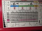
Found the suggested settings for your welder. Judging by the chart this welder is a clone of the old Lincoln SP machines as the settings chart looks identical to my old Lincoln SP135 Plus. If it's the same welder it's a good one for thin gauge sheet. I still use my old Lincoln as my bigger MIG doesn't weld thin stuff as nice.
What gauge are you working on? Chances are its probably 20 gauge or possibly 19 or 18. Use those settings in the chart as a staring point. If you are blowing through with those settings then we need to look at your technique. Cut the wire so that you have around a 1/4" of stickout from the contact tip. Posistion the wire so it's touching the panels only place it between the panels in the gap. Make sure your gap is around .030. Don't guess at it, measure it. You could be trying to fill a bigger gap than you think. Squeeze the trigger and release. You can do a little wiggle when you squeeze if you want. Remember you are squeezing and releasing, it should be no longer than a second, if that.
What gas are you using? 75/25 or 100% CO2. If using CO2 you should switch to 75/25 argon, co2.
Settings Chart
Last edited:
Chris_Hamilton
Trying to be the best me, I can be
Practice your technique on a solid piece of sheet. Once you can consistently do it move on to two practice pieces and trying joining them using the spot technique. Don't make your practice on the the car. Practice with scrap until you can get your settings dialed in and get a feel for doing it.
I recently had a chance to demo a hand held laser welder, and it is impressive. It does tight gap butt welding very good, so I was trying it with a gap. There was a choice between .023 and .030 wire, so I started out with .023 wire on 20 ga metal and had no luck at all when trying to make a tack or for welding from a tack with a gap of about .030-.040 . Switching from .023 to .030 and starting the tack on one side of the gap, and flicking the welding head toward the other side made the difference. It wasn't a pretty tack like it would be with a tight butt, but it worked. I think .040 would have been even better.have tried using both Flux .030 and Shielded .023 wires with the same results.
For mig welding it is recommended to use the same size wire as the metal being welded. Personally, I think that is with the thought that there will be a gap.