Wagon Progress

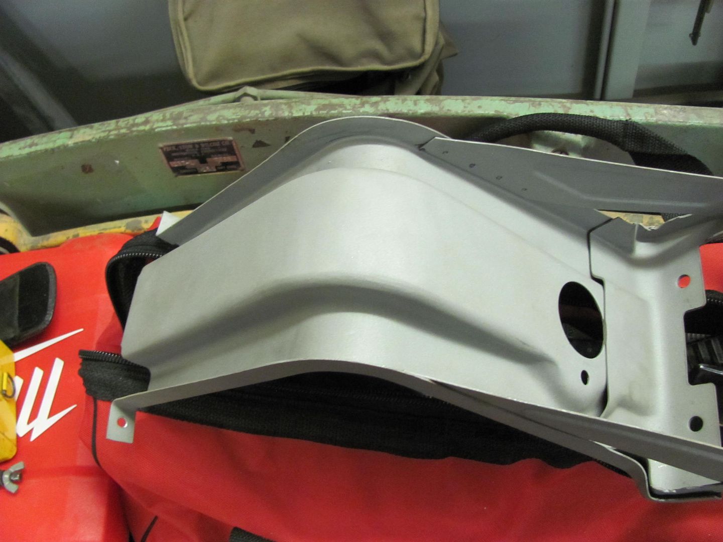
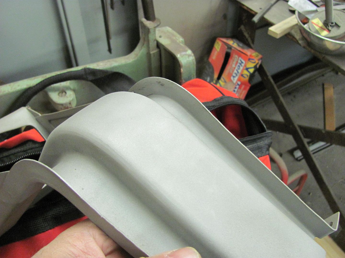
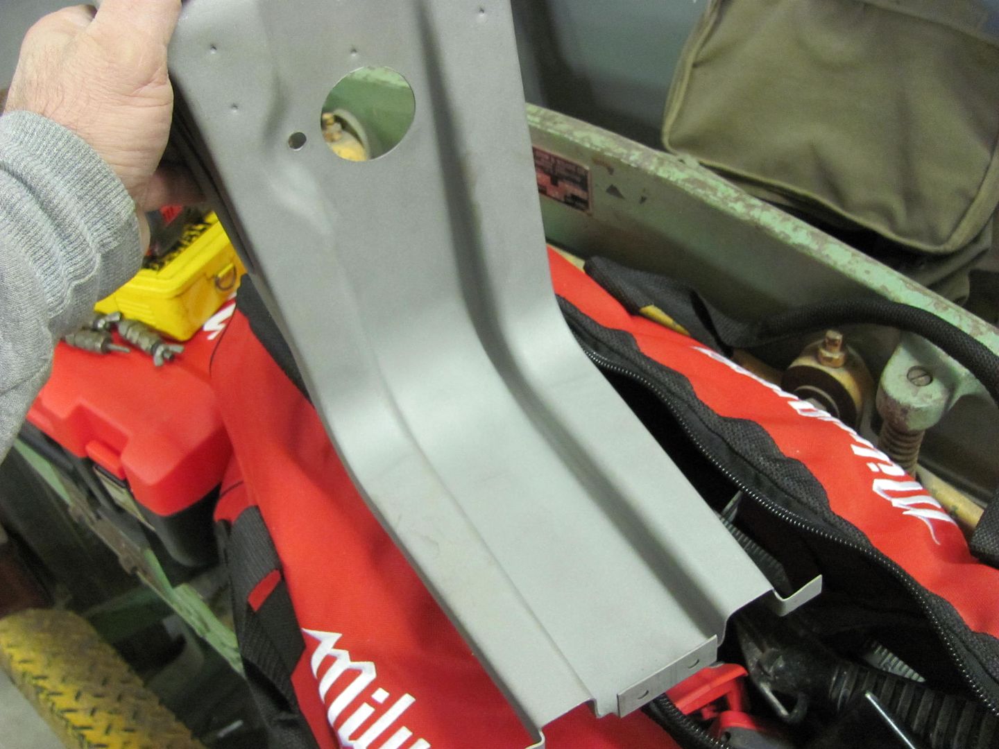
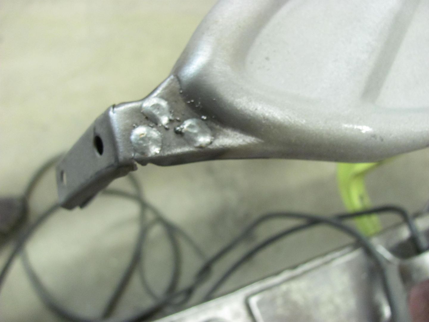
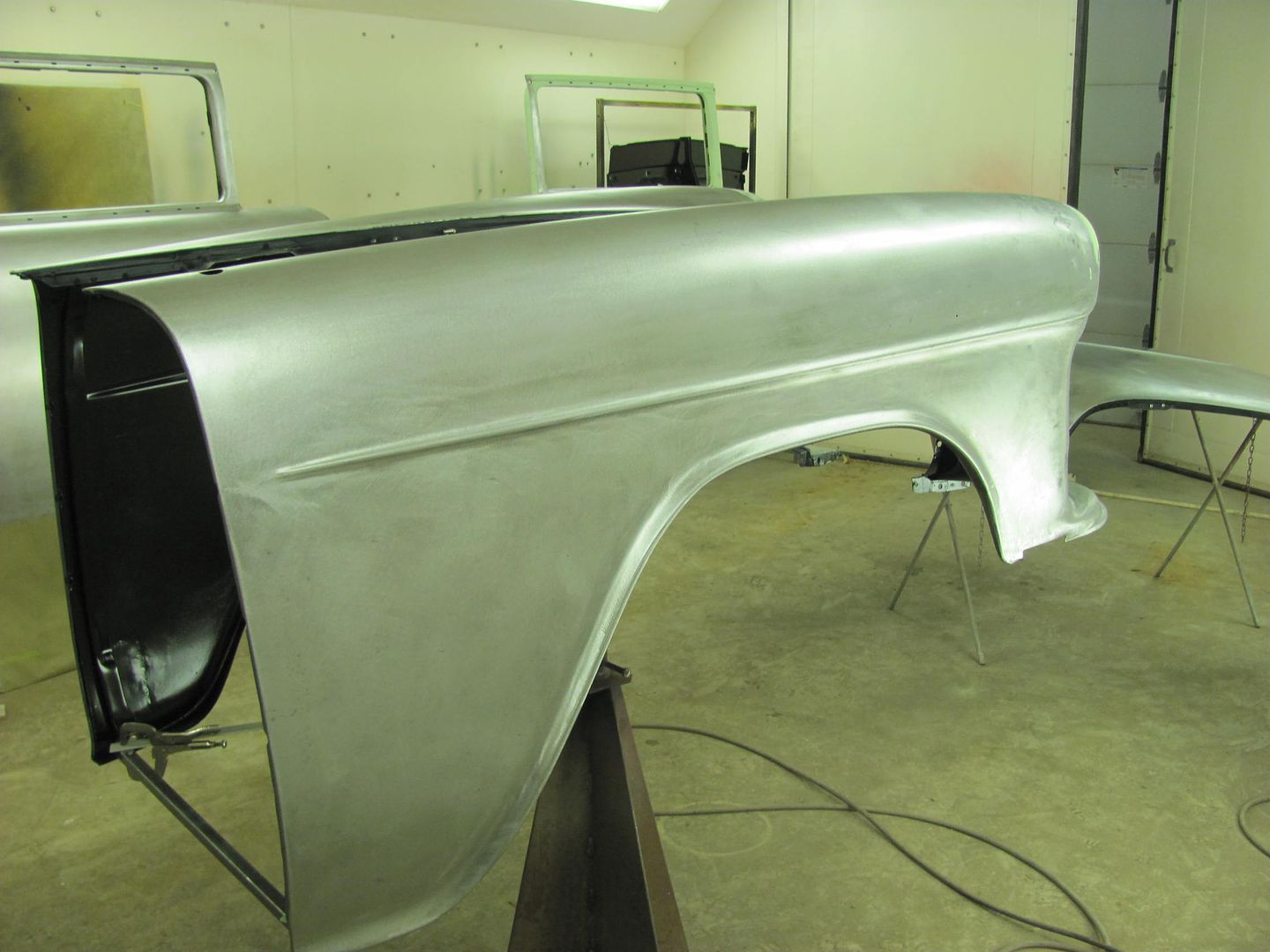
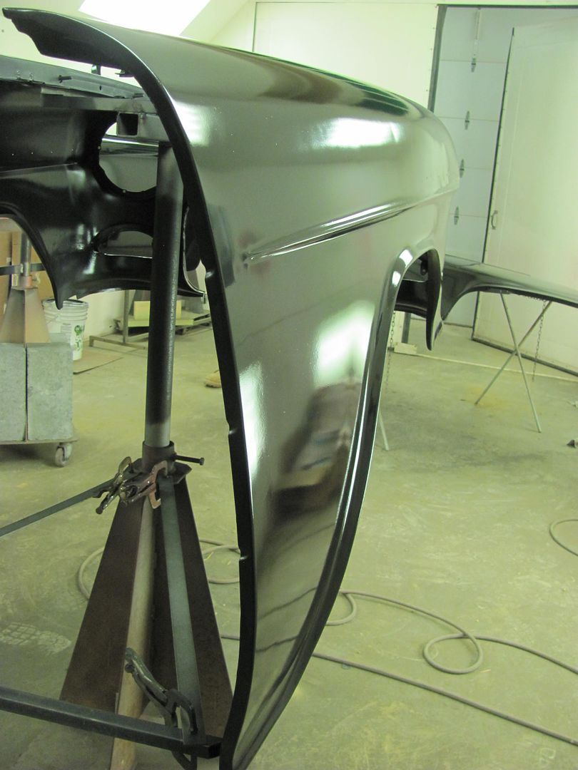
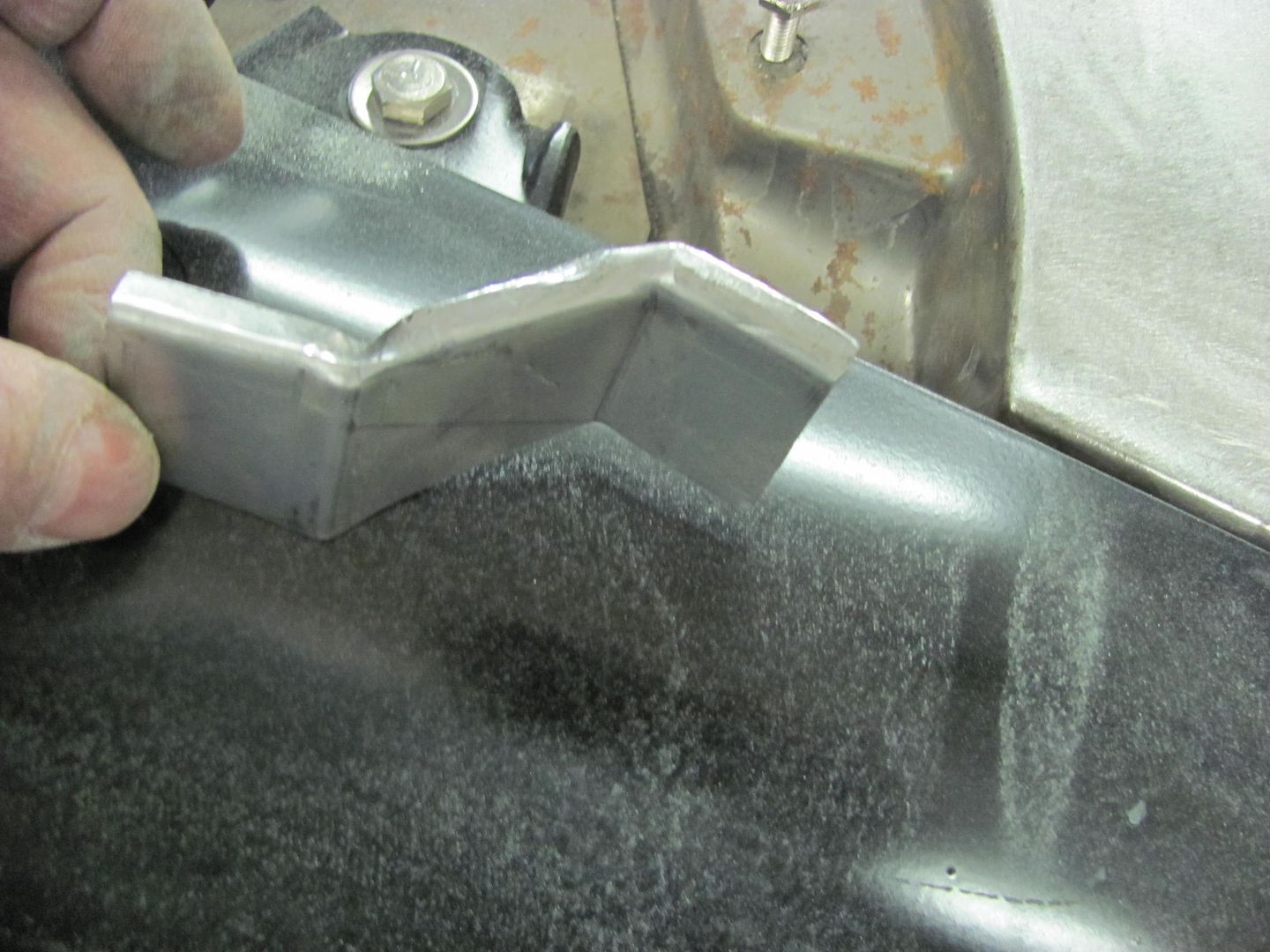
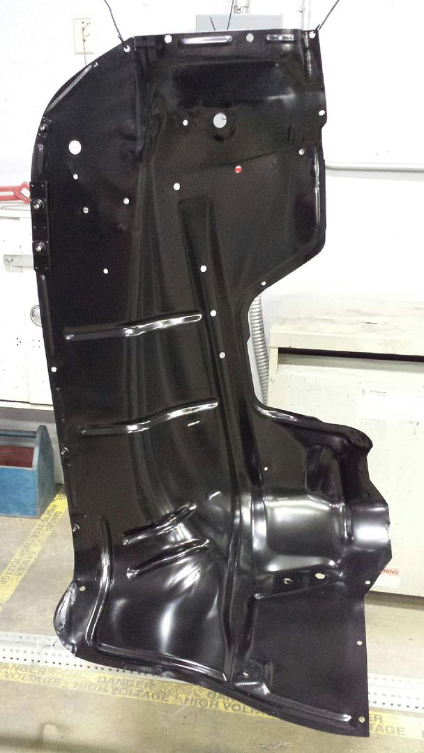
Sneak preview of the powder coating, here's one of the inner fenders...


Picture1867.jpg


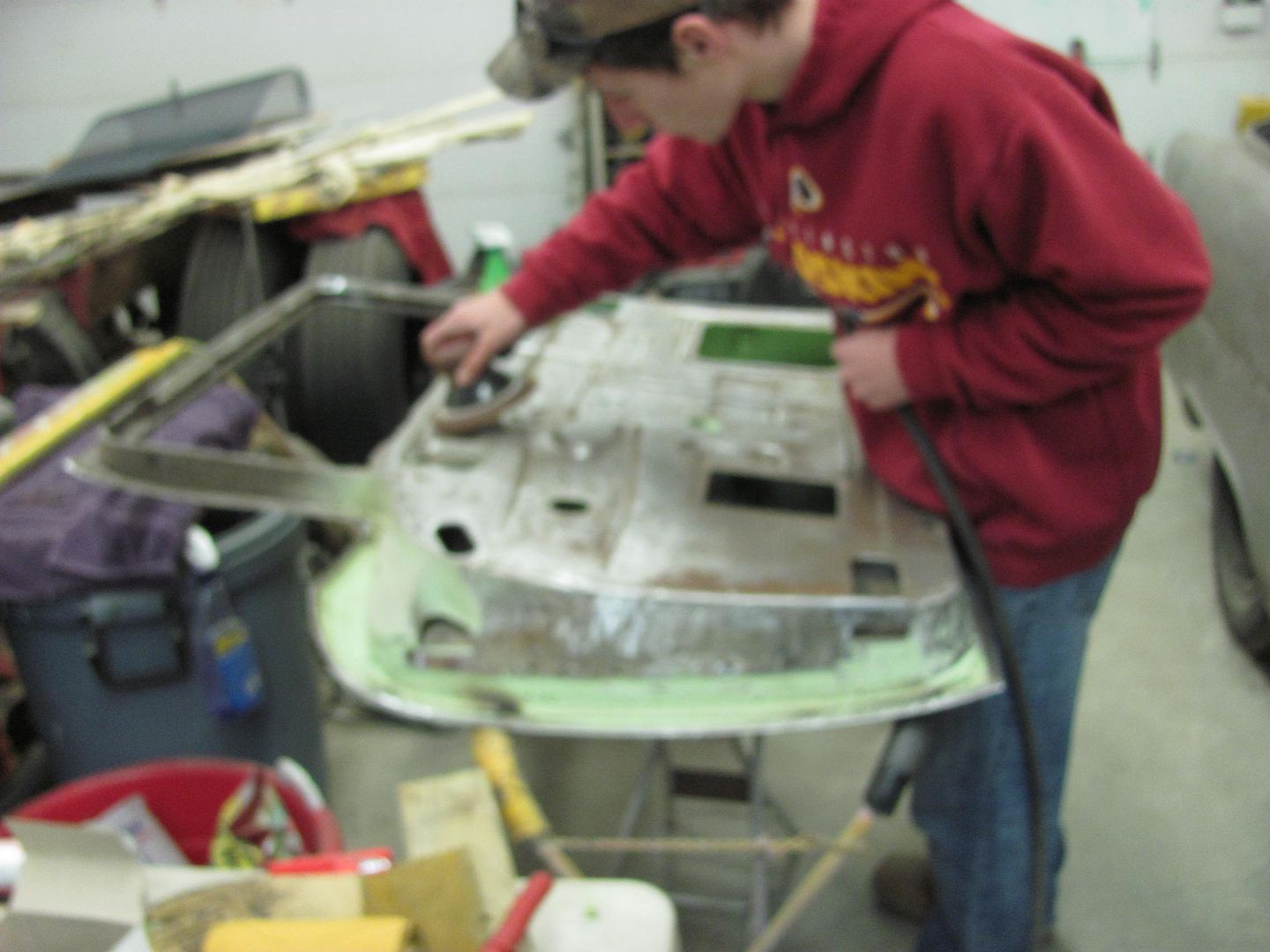
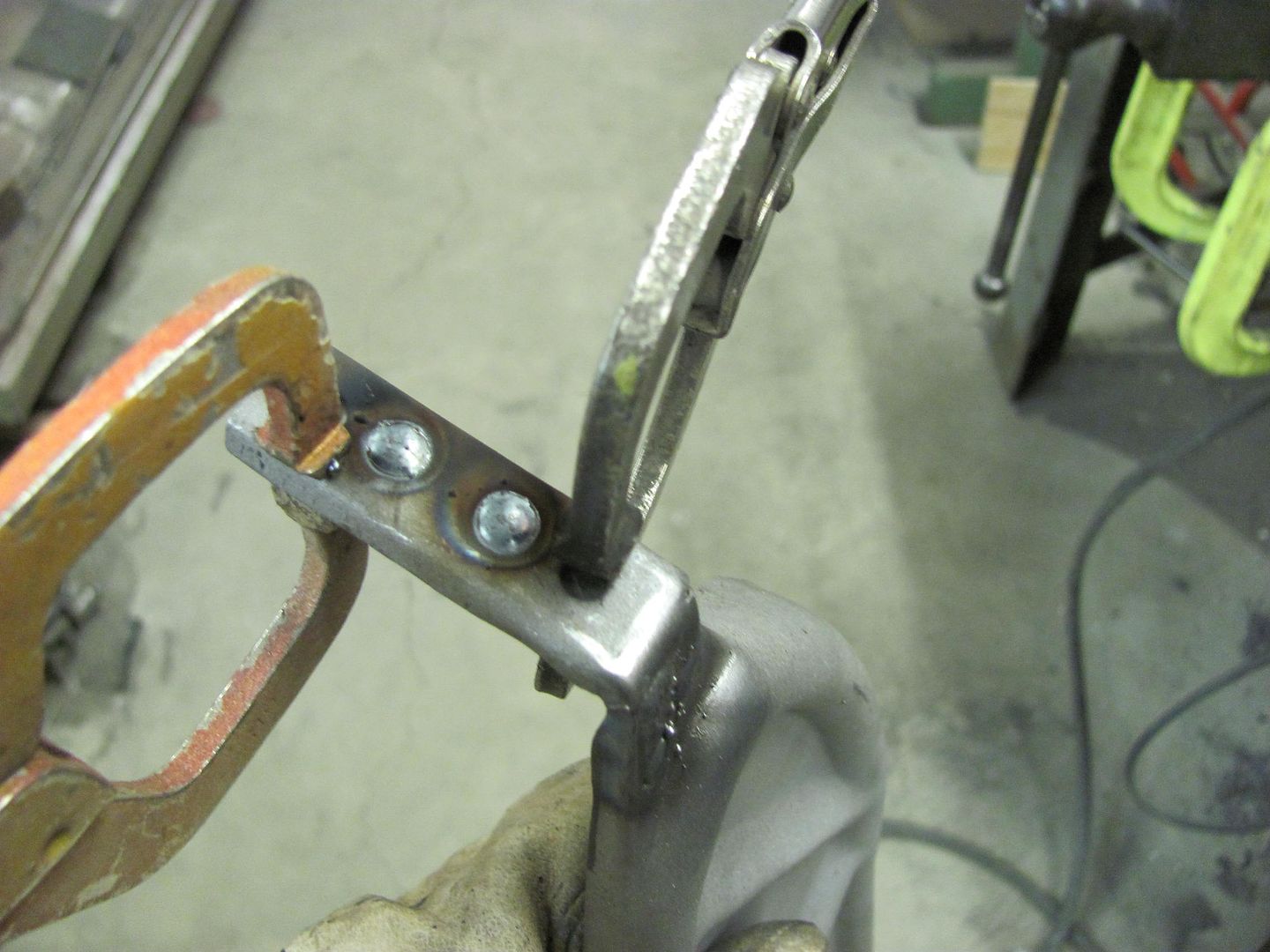
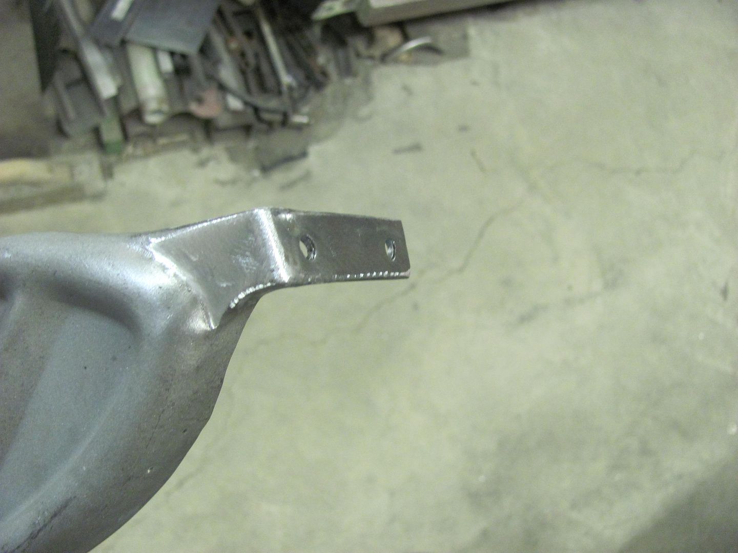
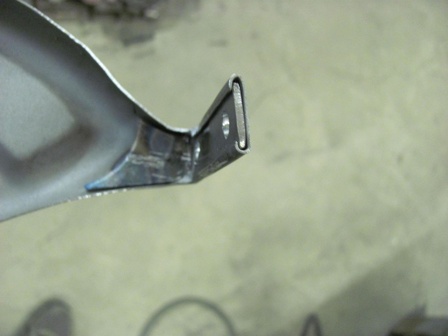
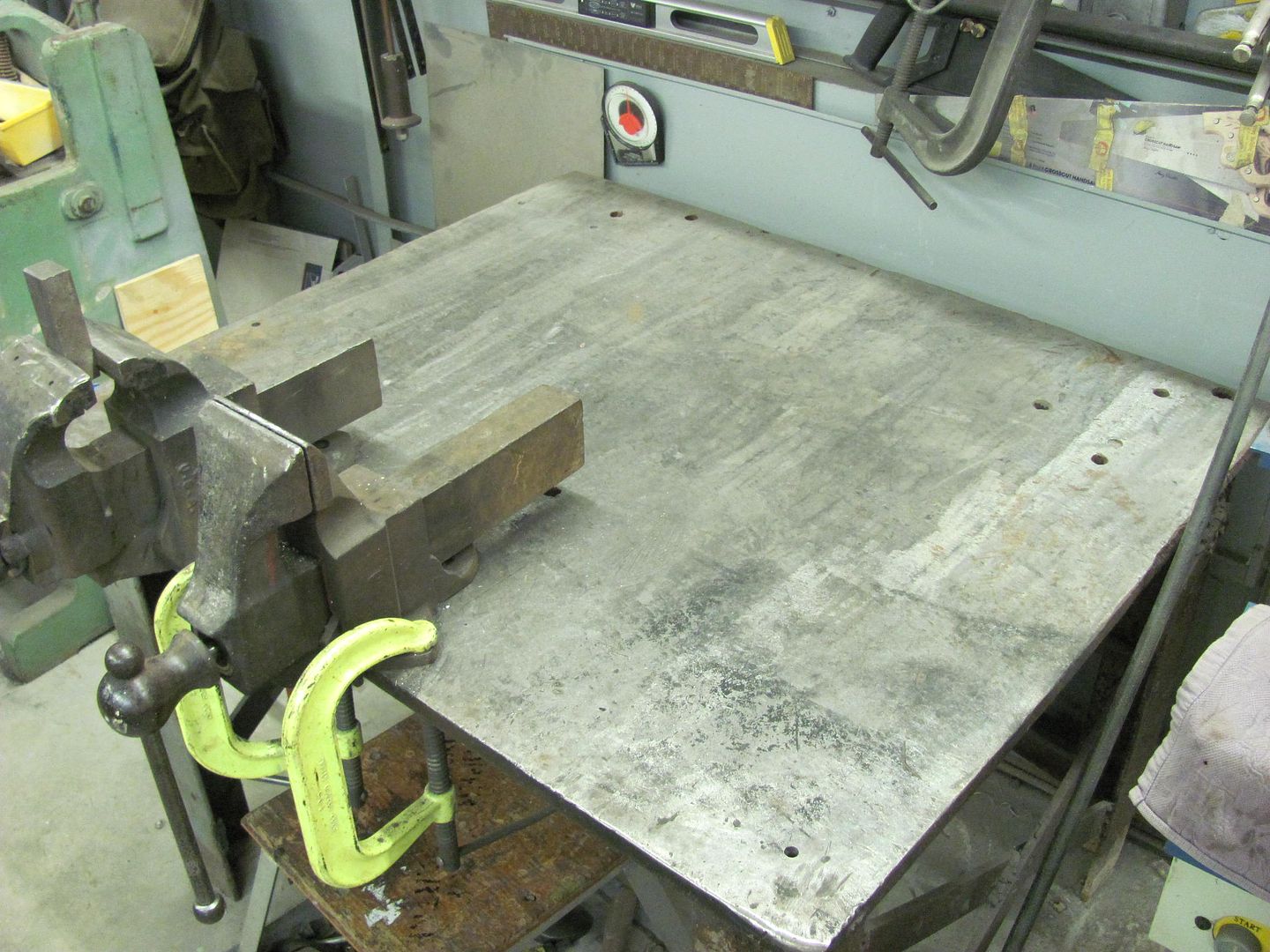
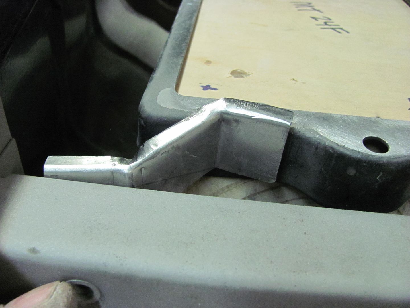
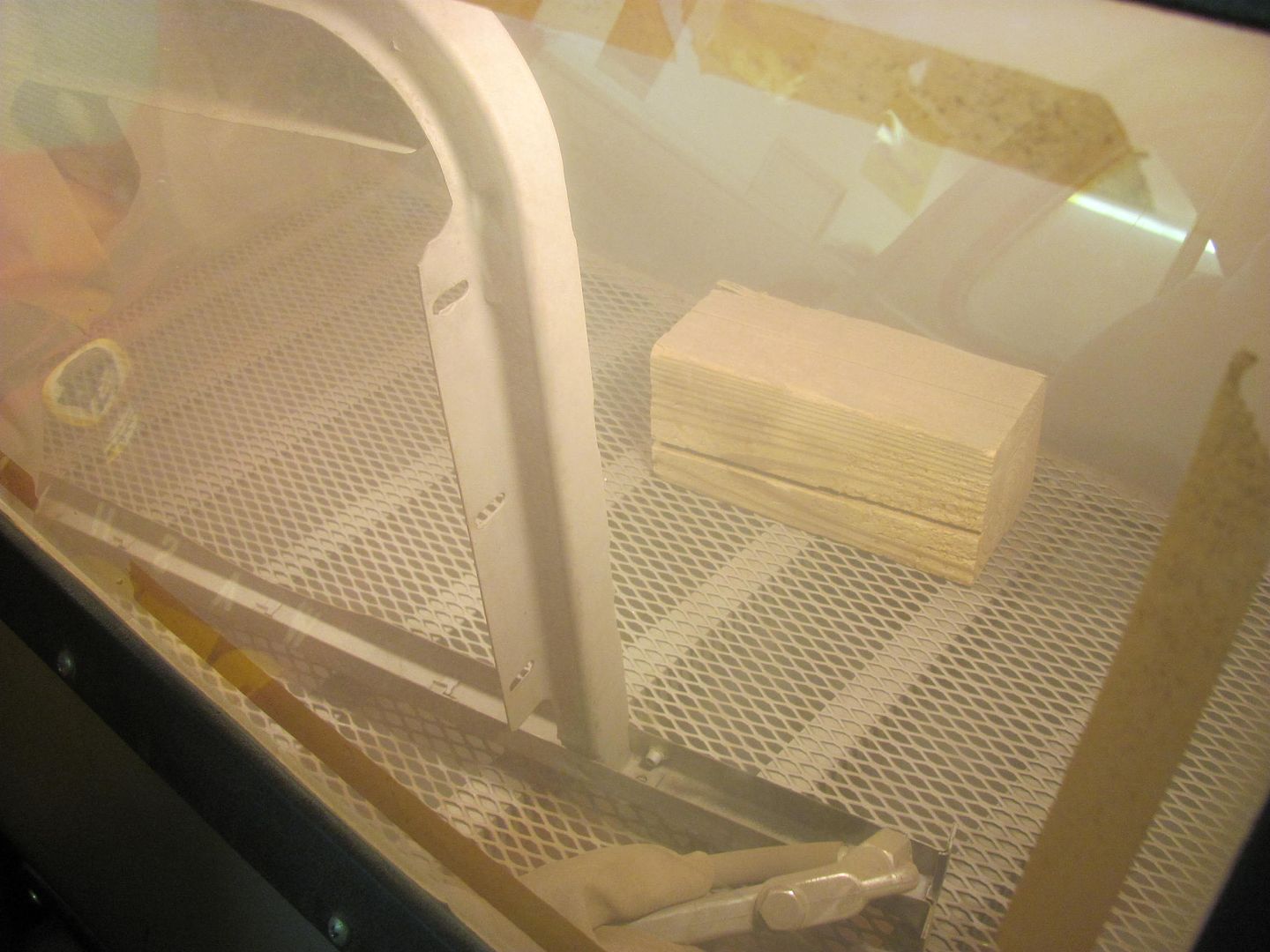
Kyle working on more media blasting, we should have another batch for powder coating this weekend....


Picture1866.jpg


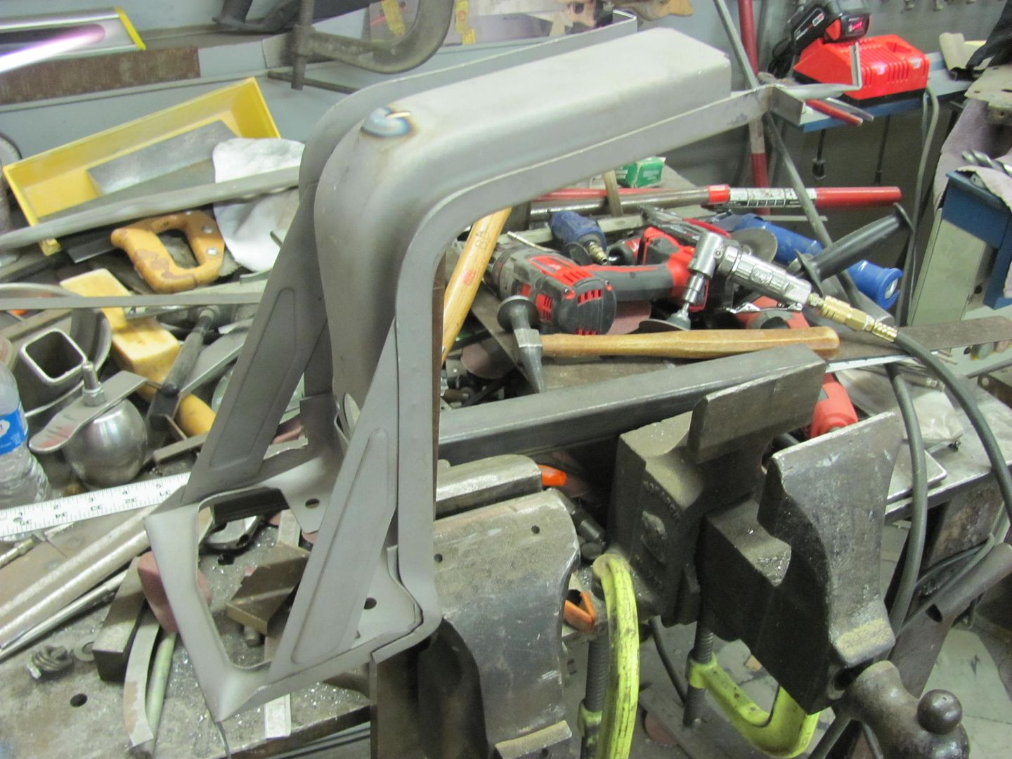
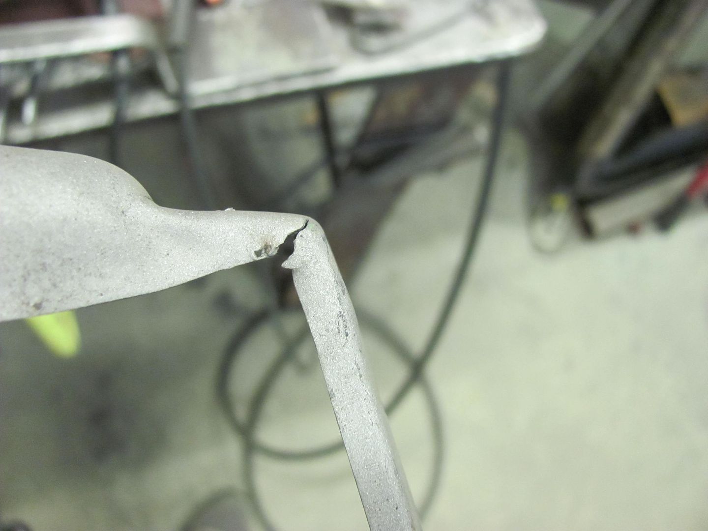
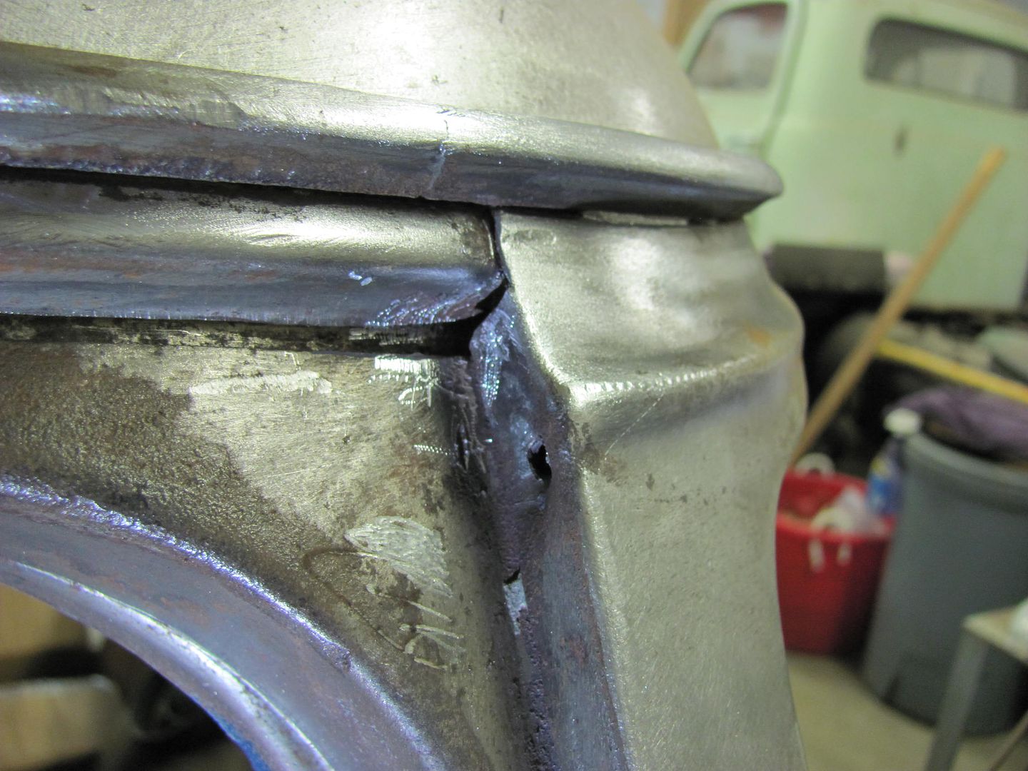
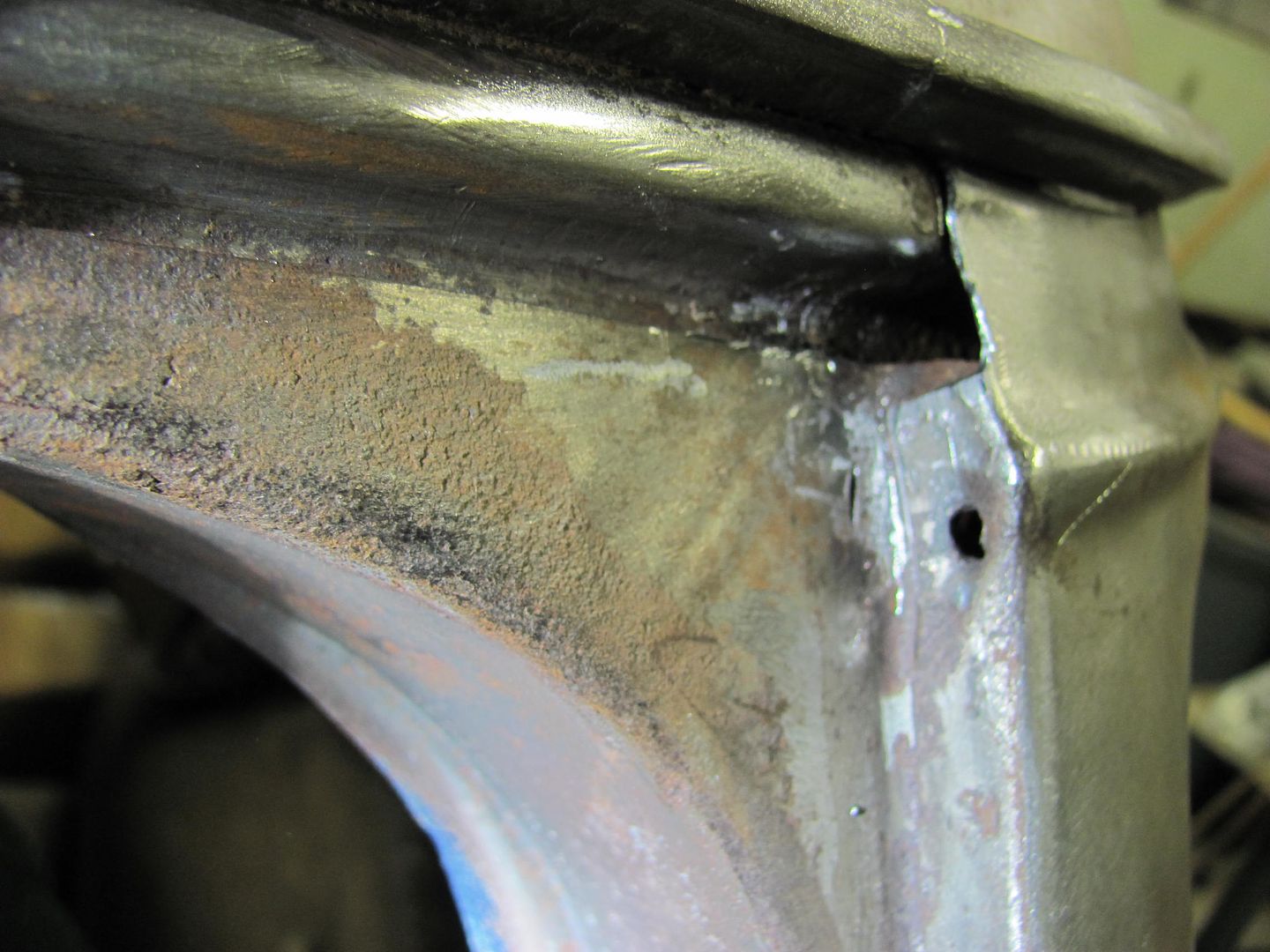
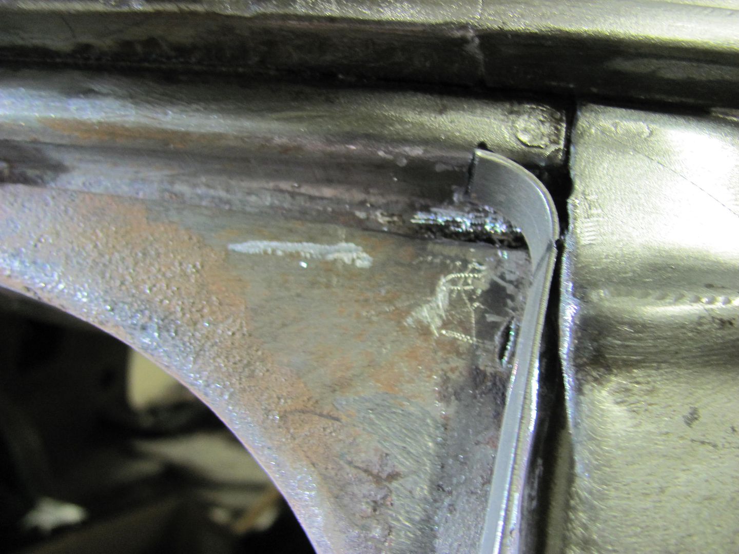
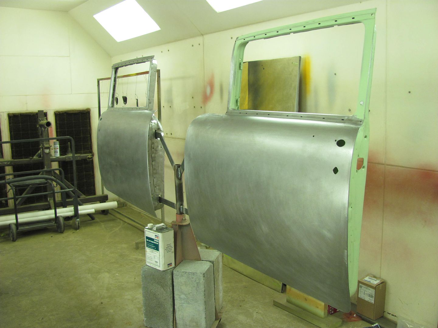
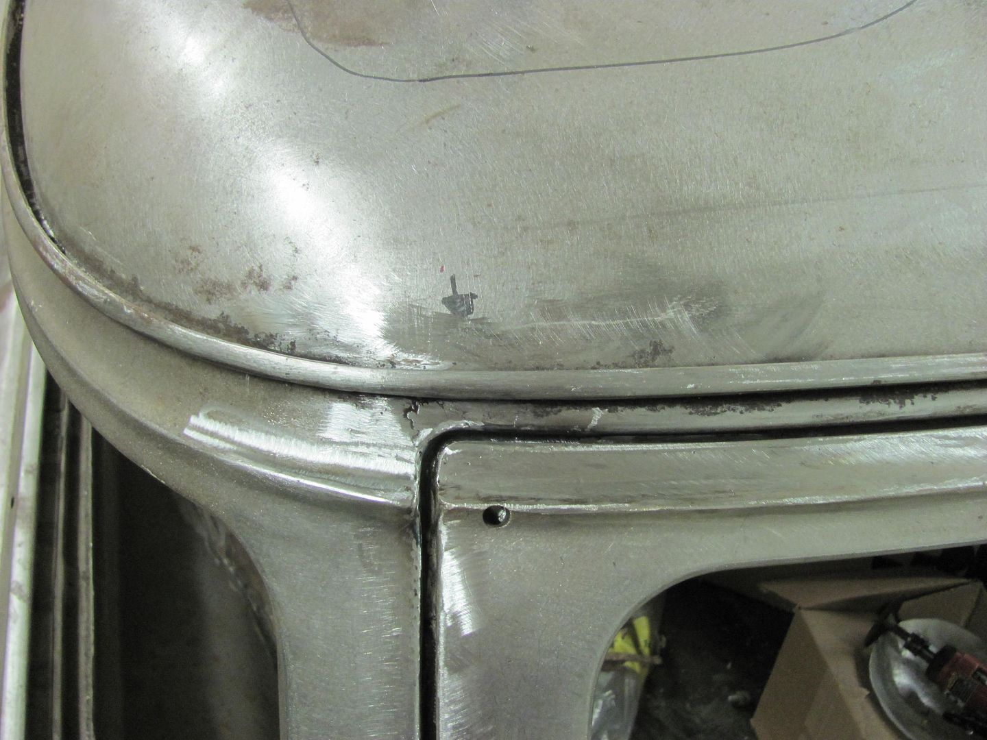
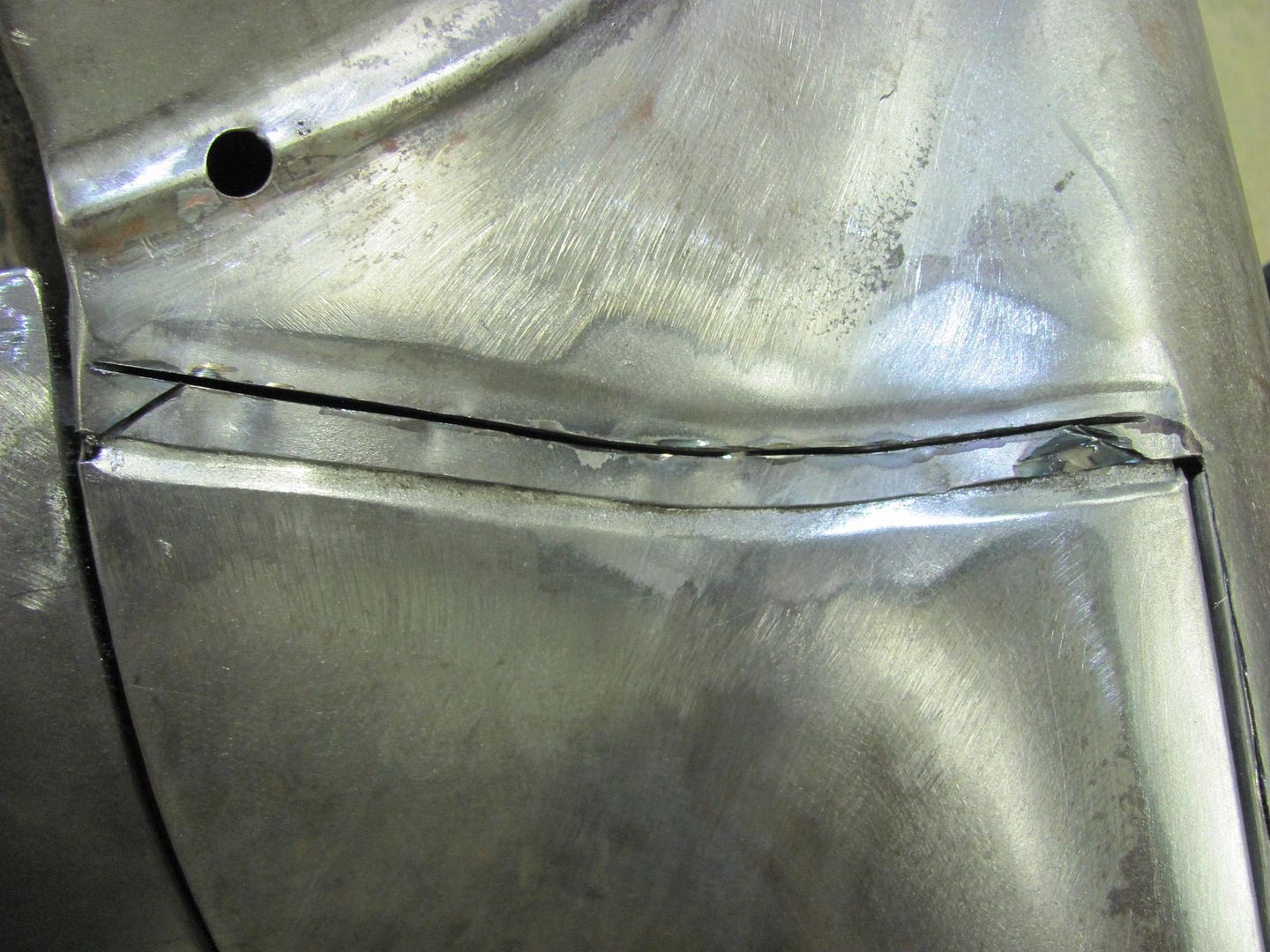
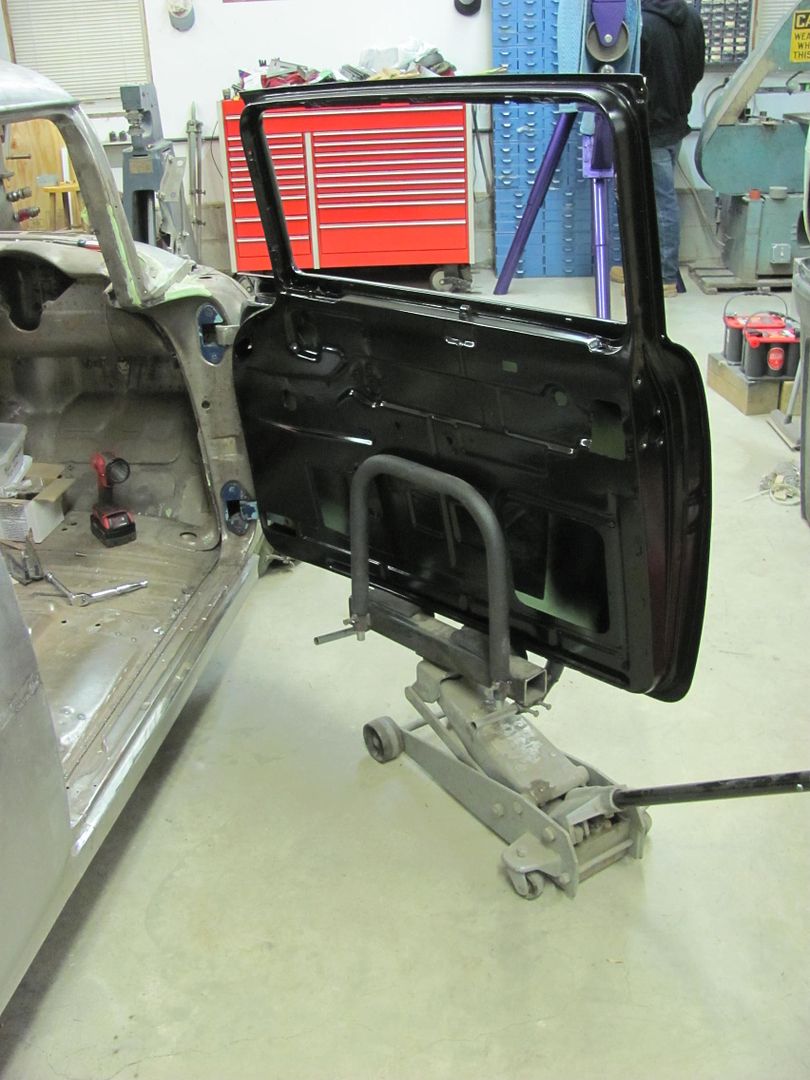
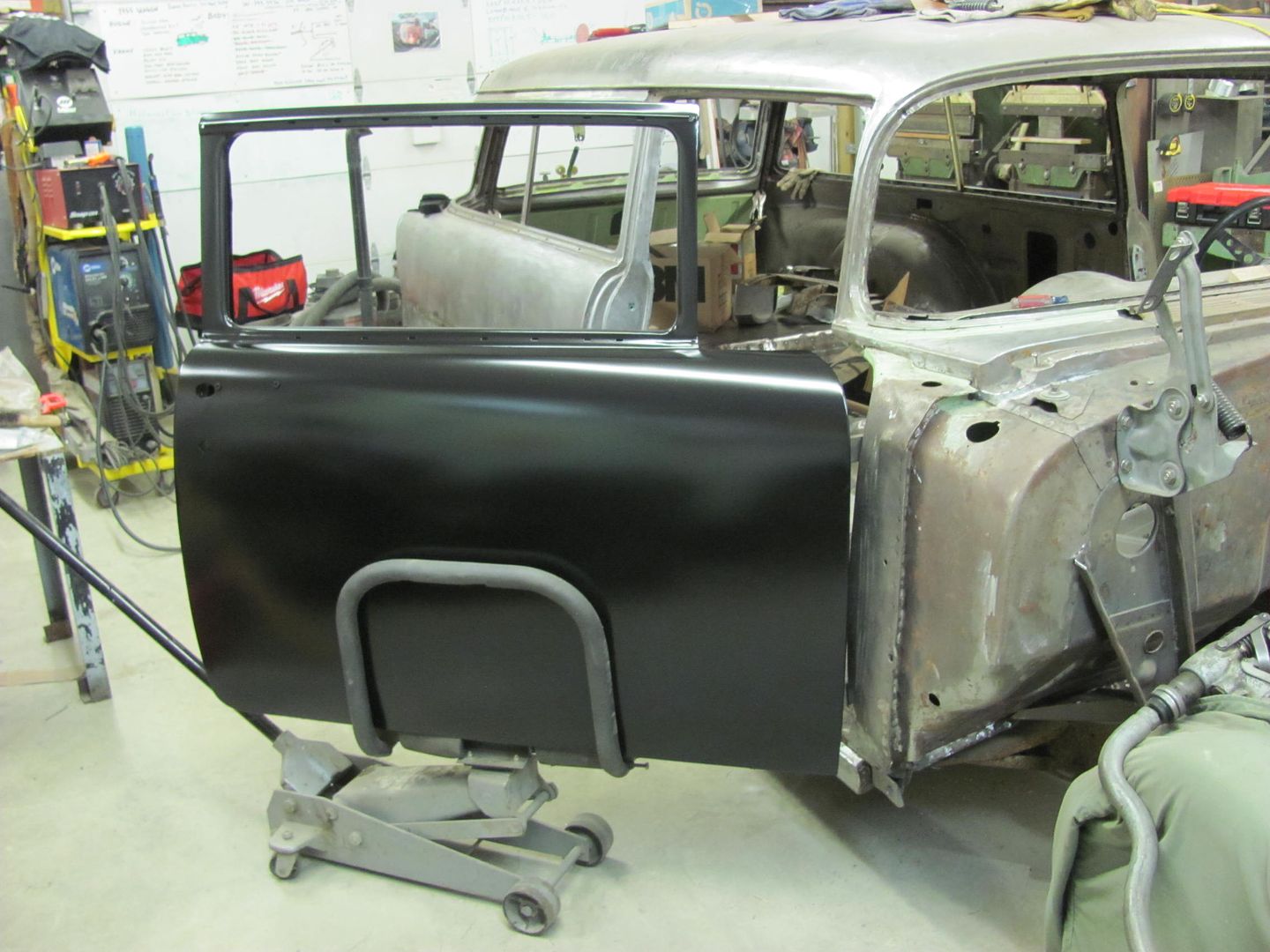
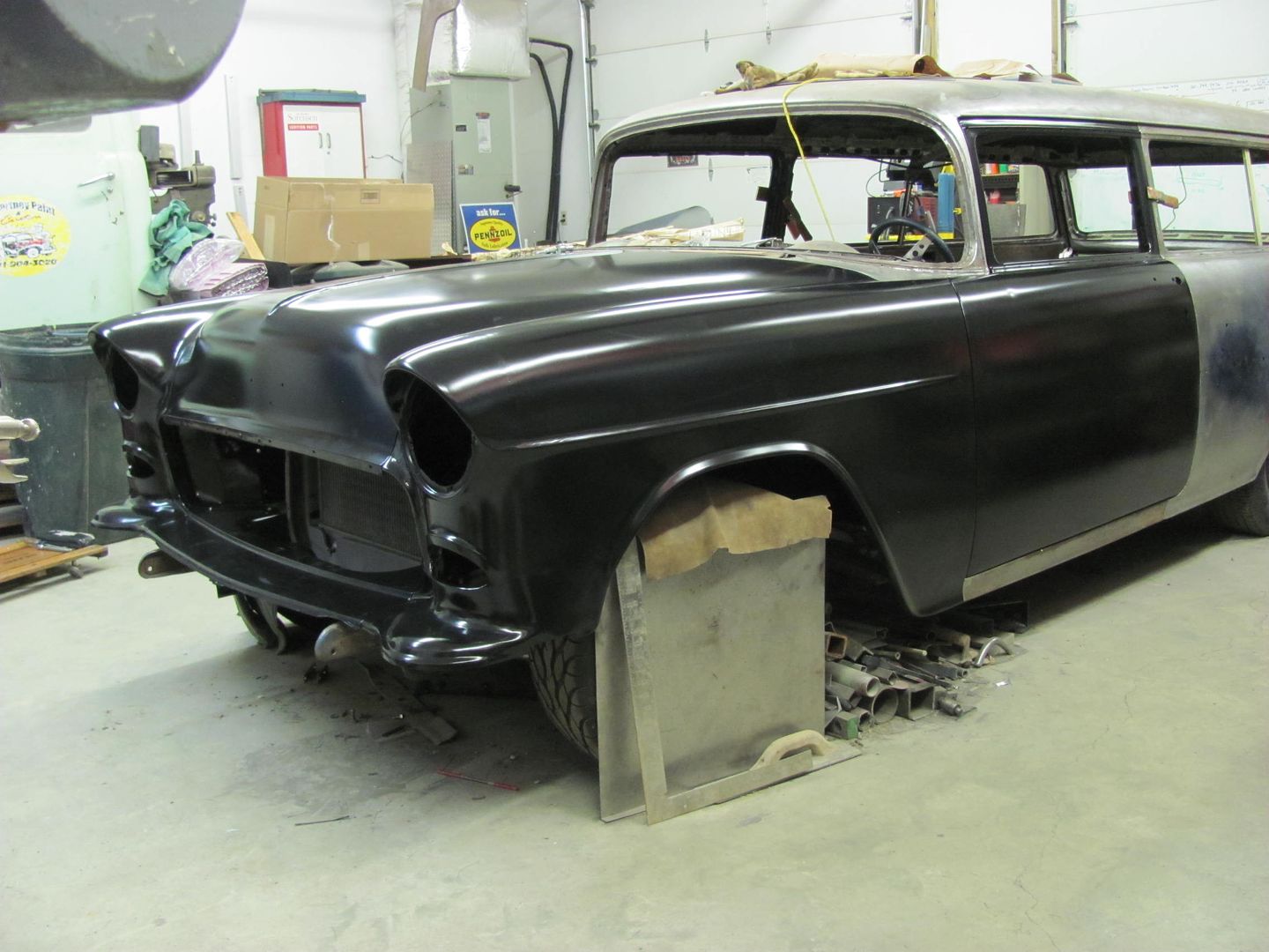
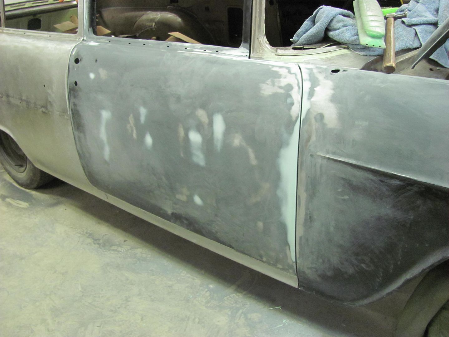
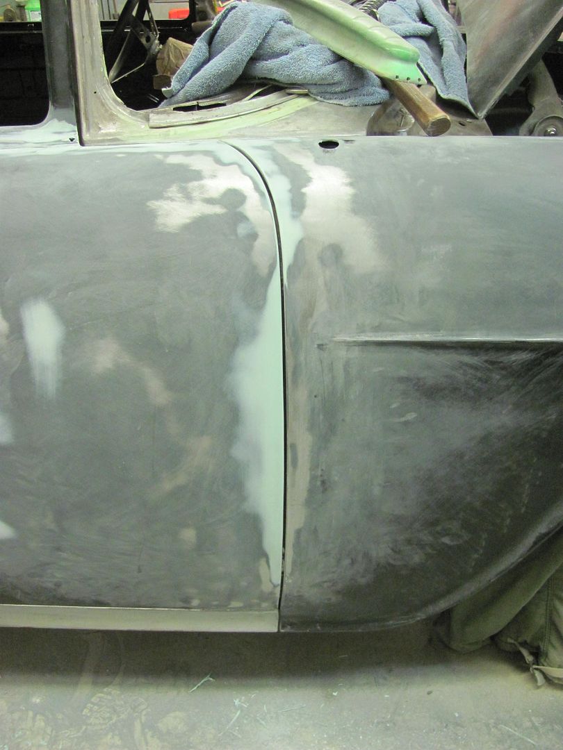
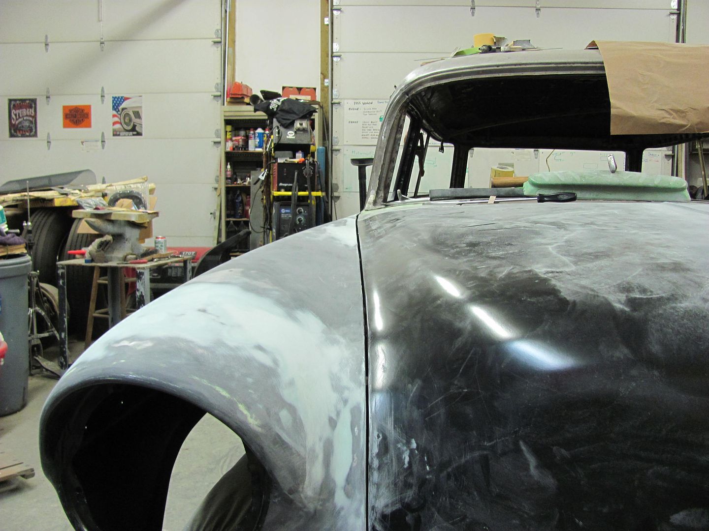
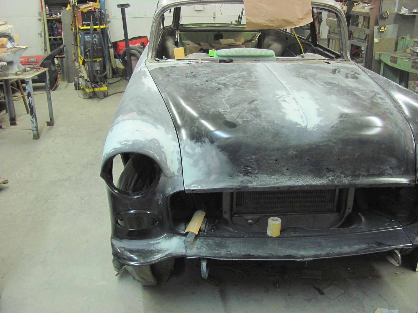
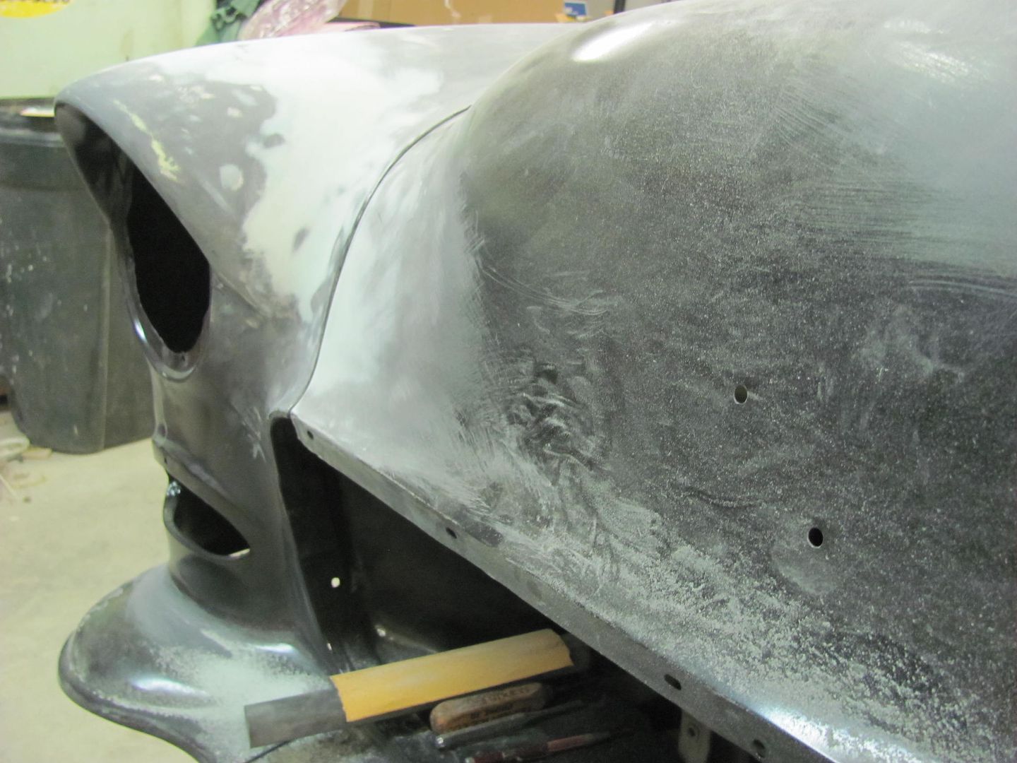
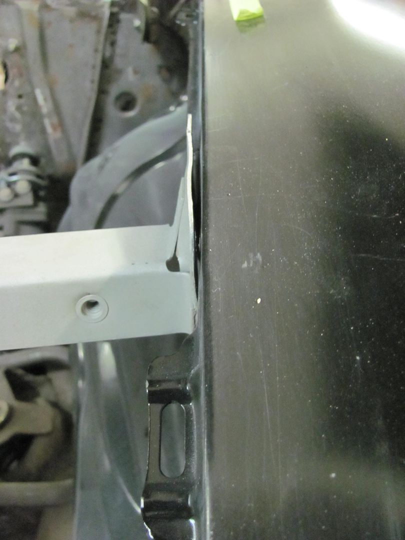
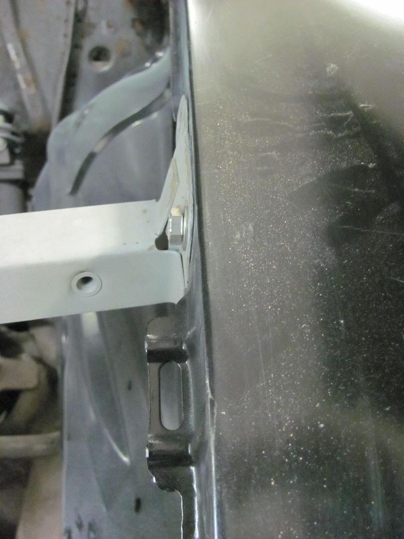
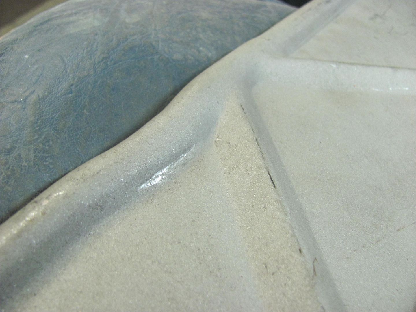
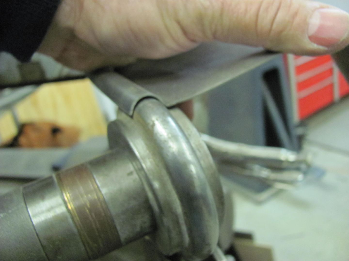
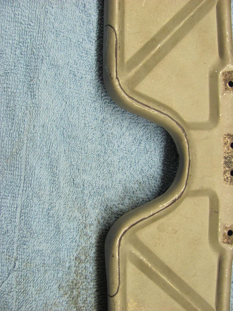
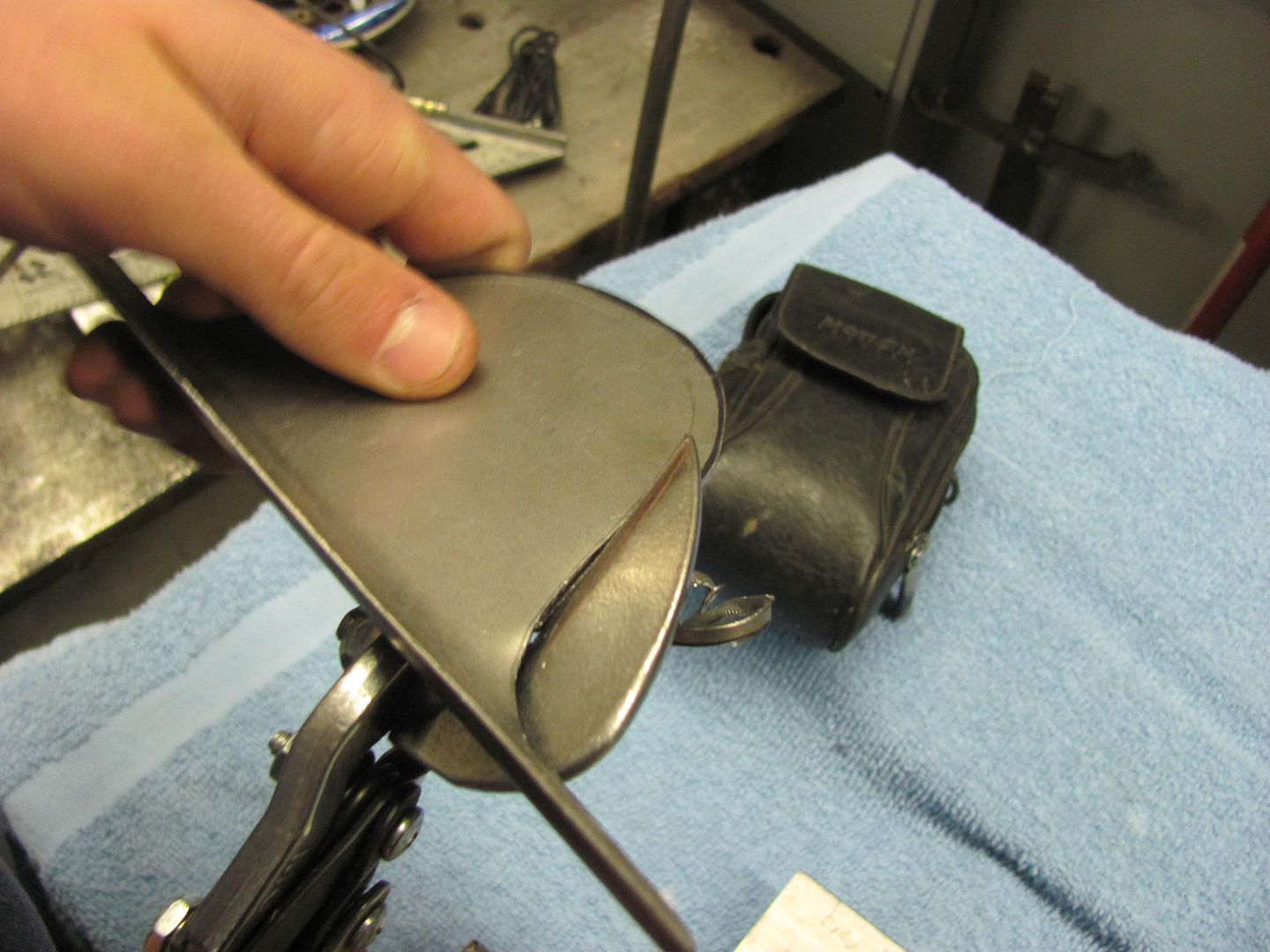
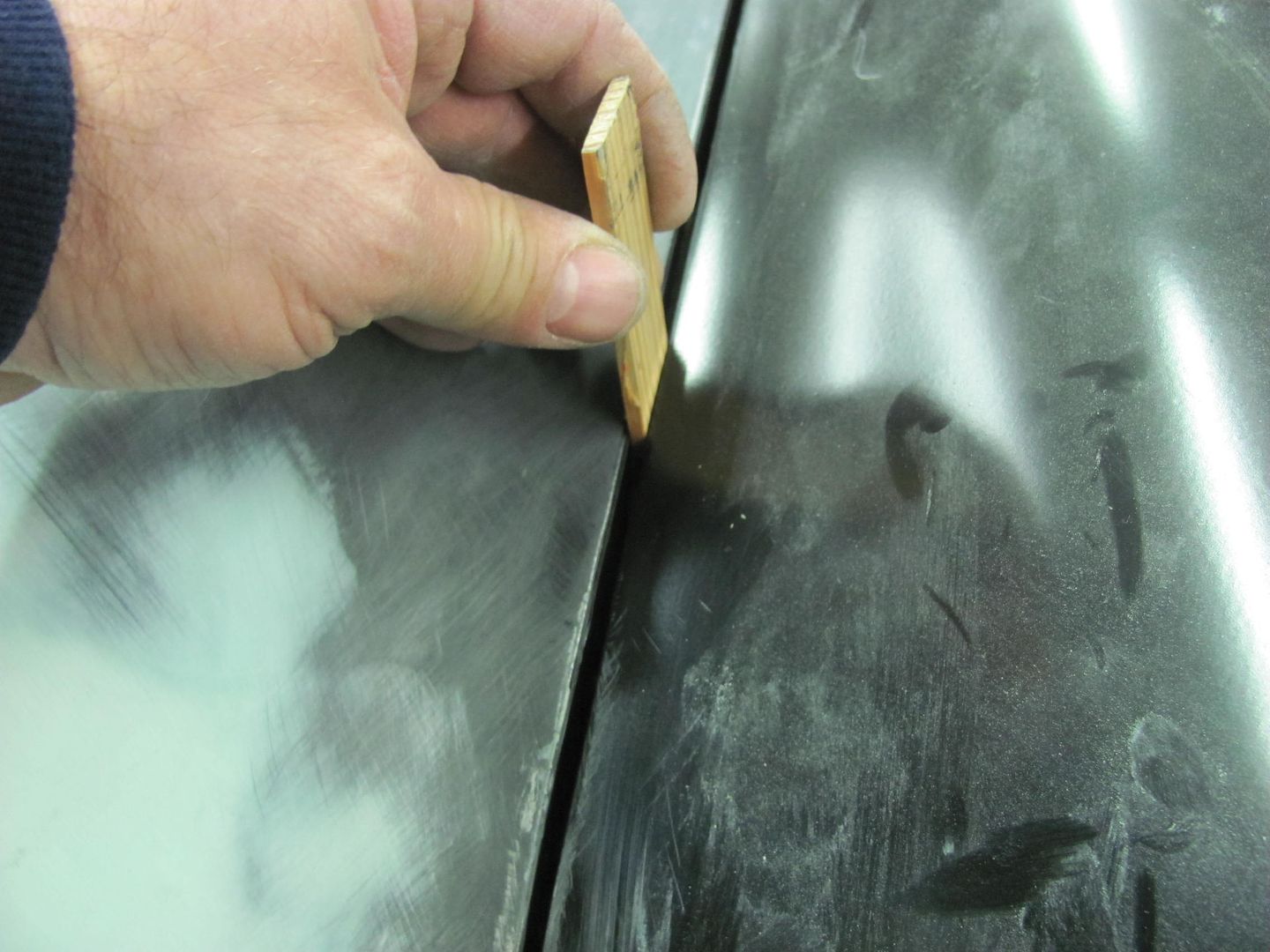
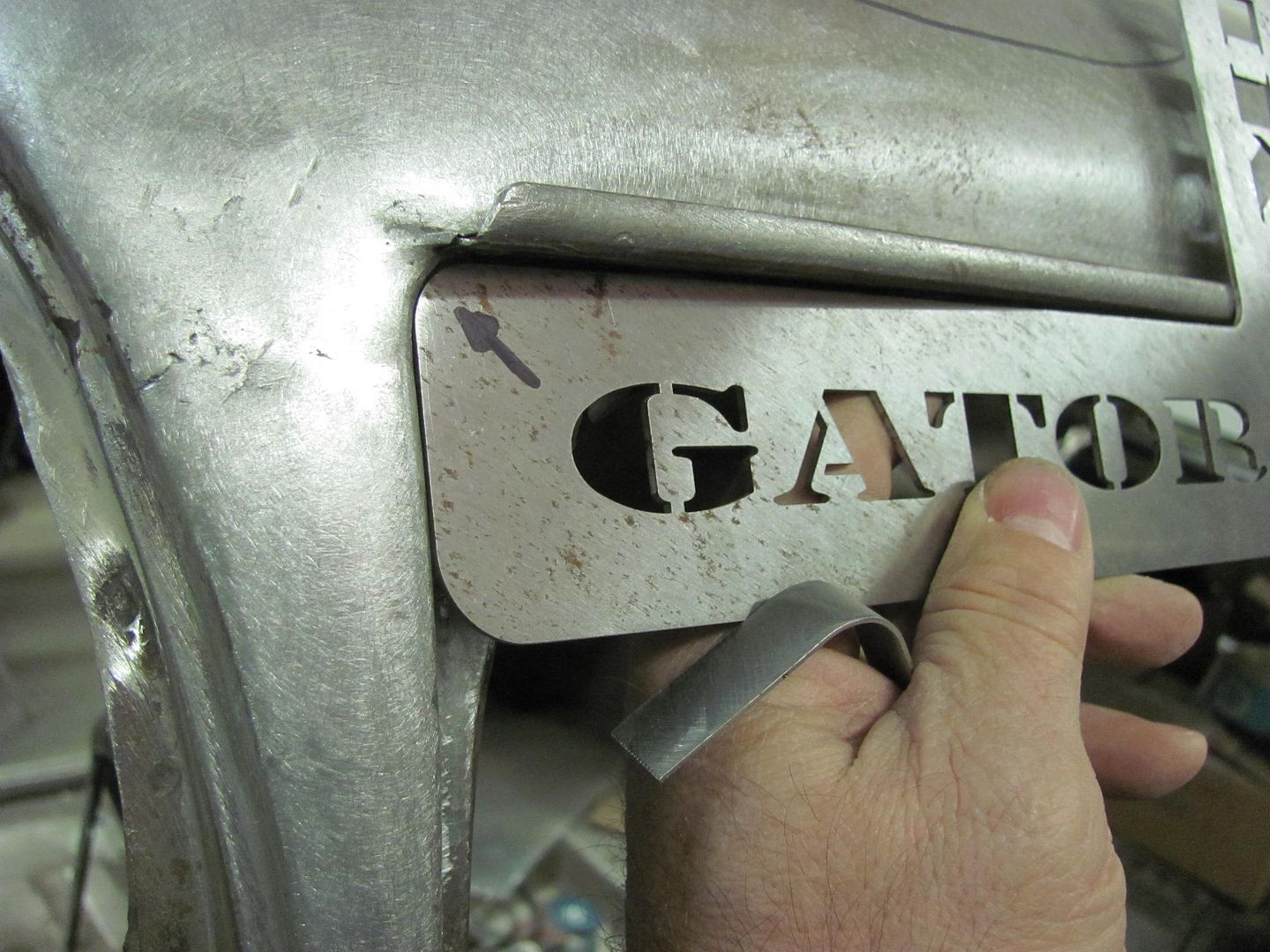
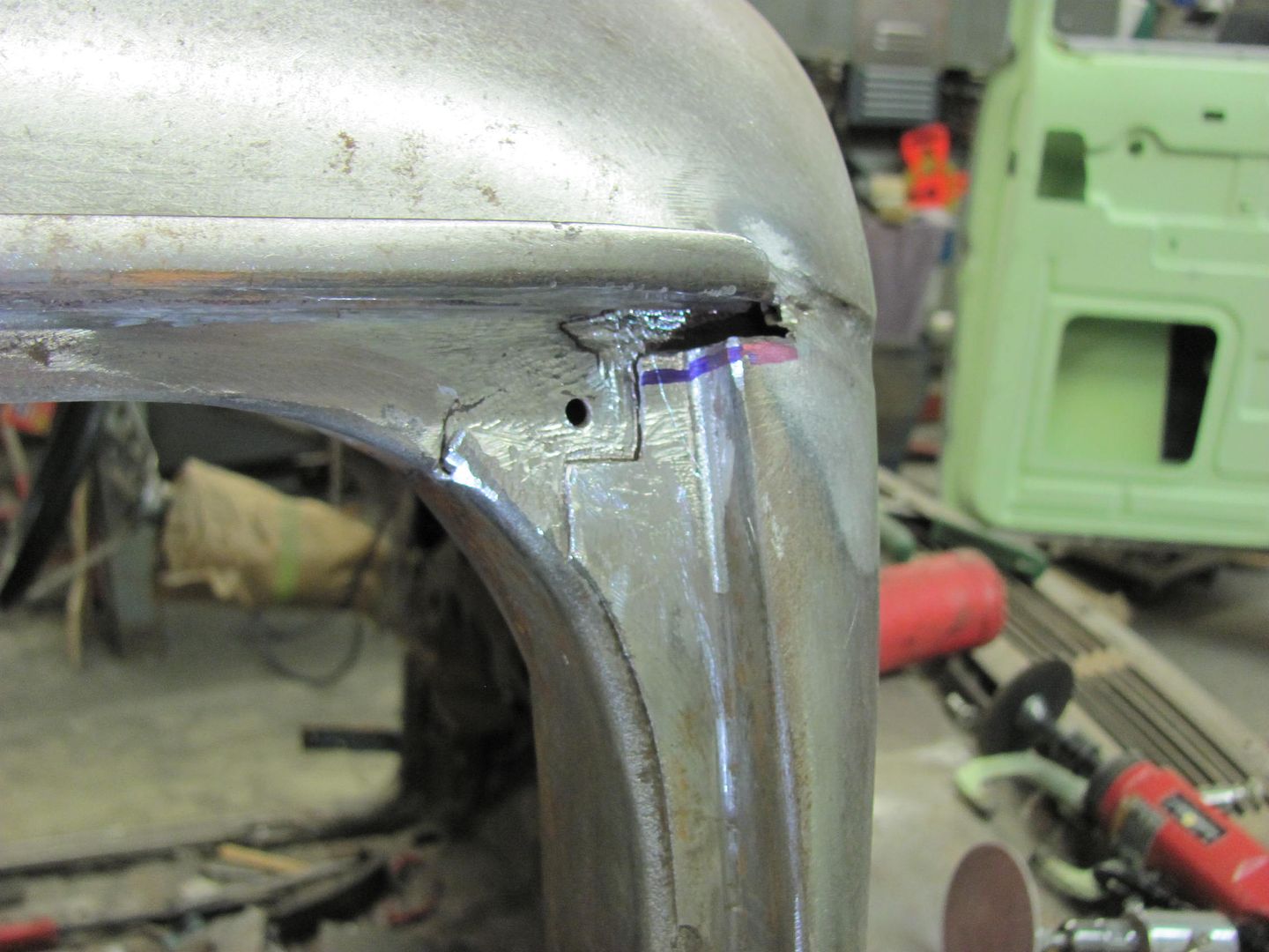
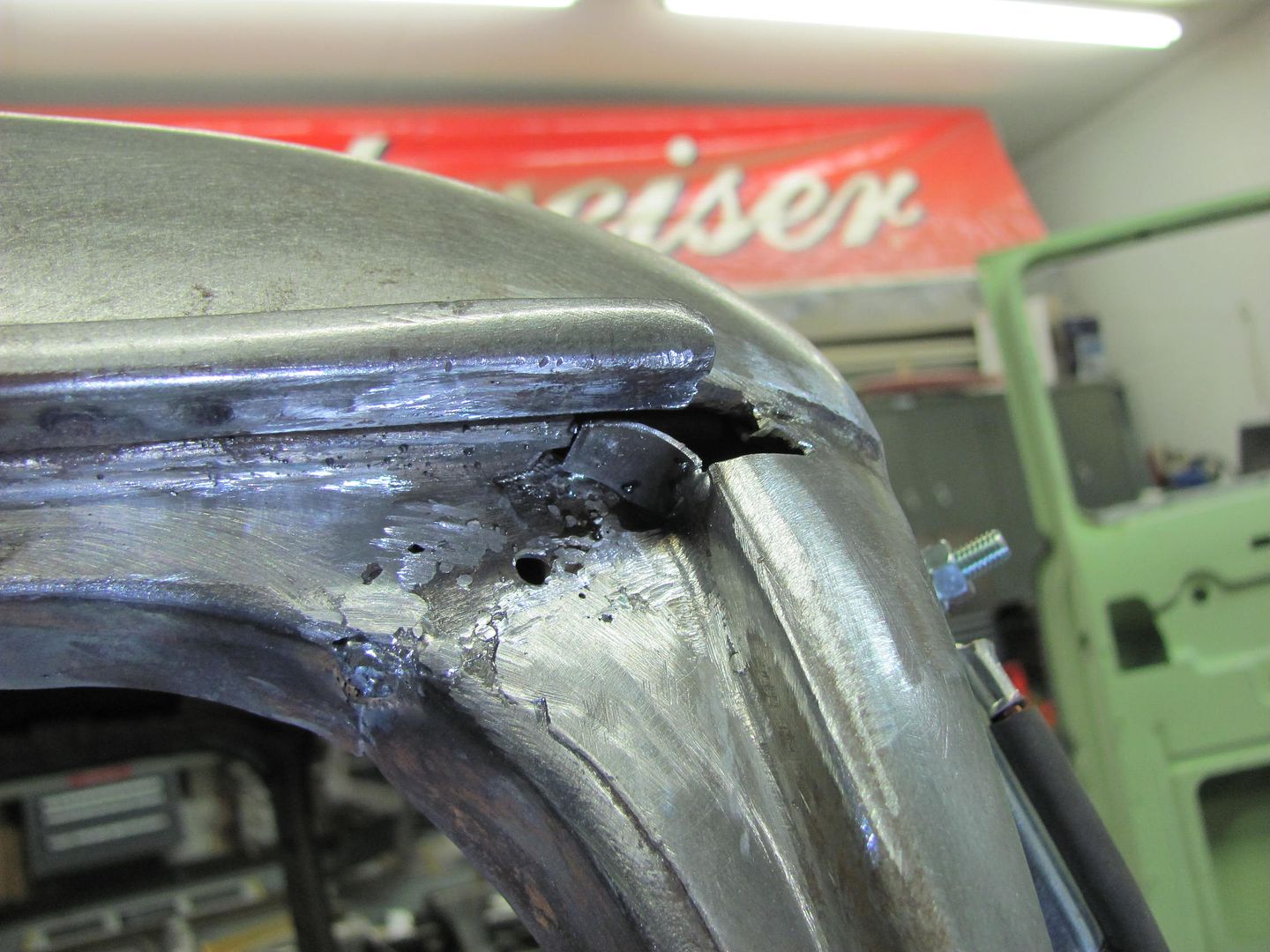
With the passenger door removed and out of the way, I worked on the radius-ing and repairing of the lead gap seam. First to check the radius of the completed driver's side with the Gatormeet radius gauge...


Picture1851.jpg


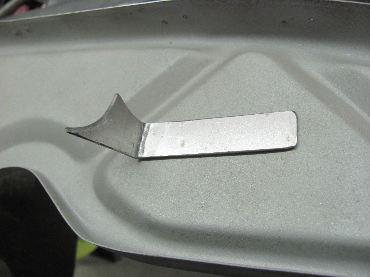
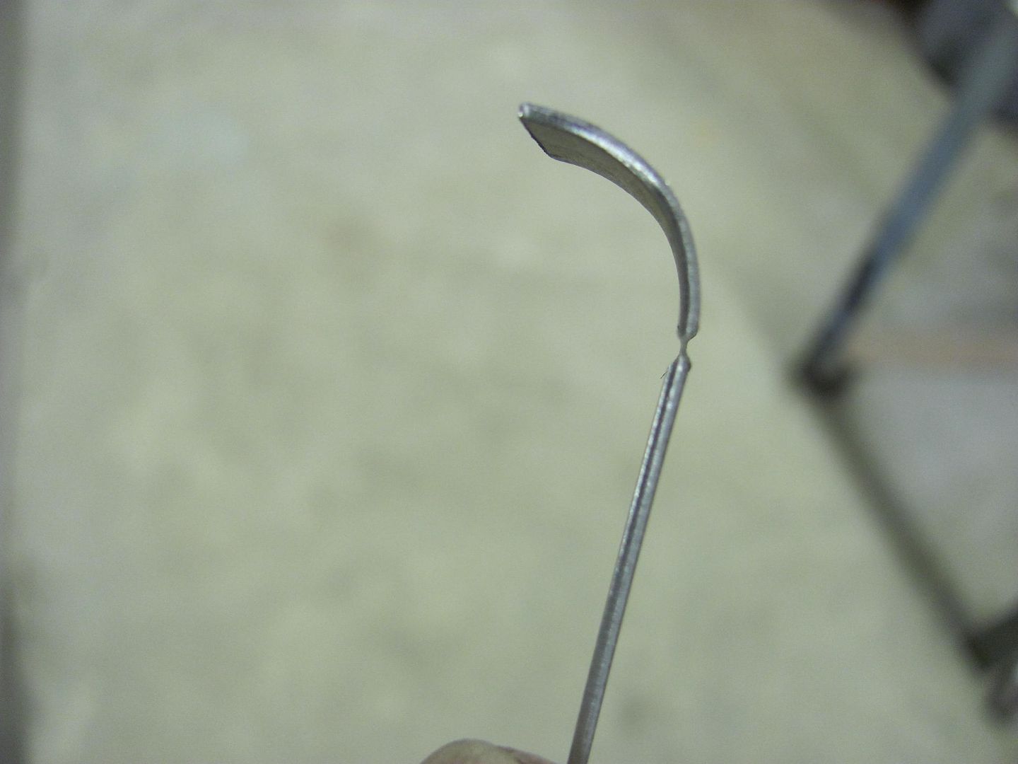
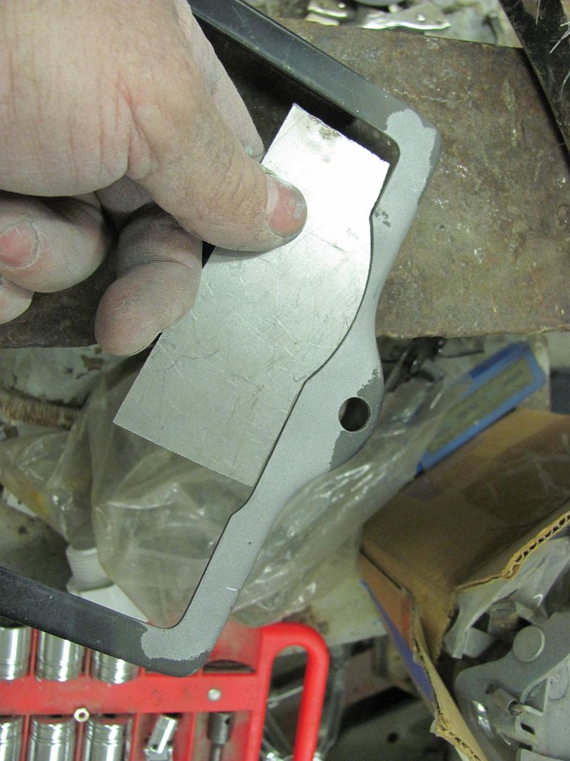
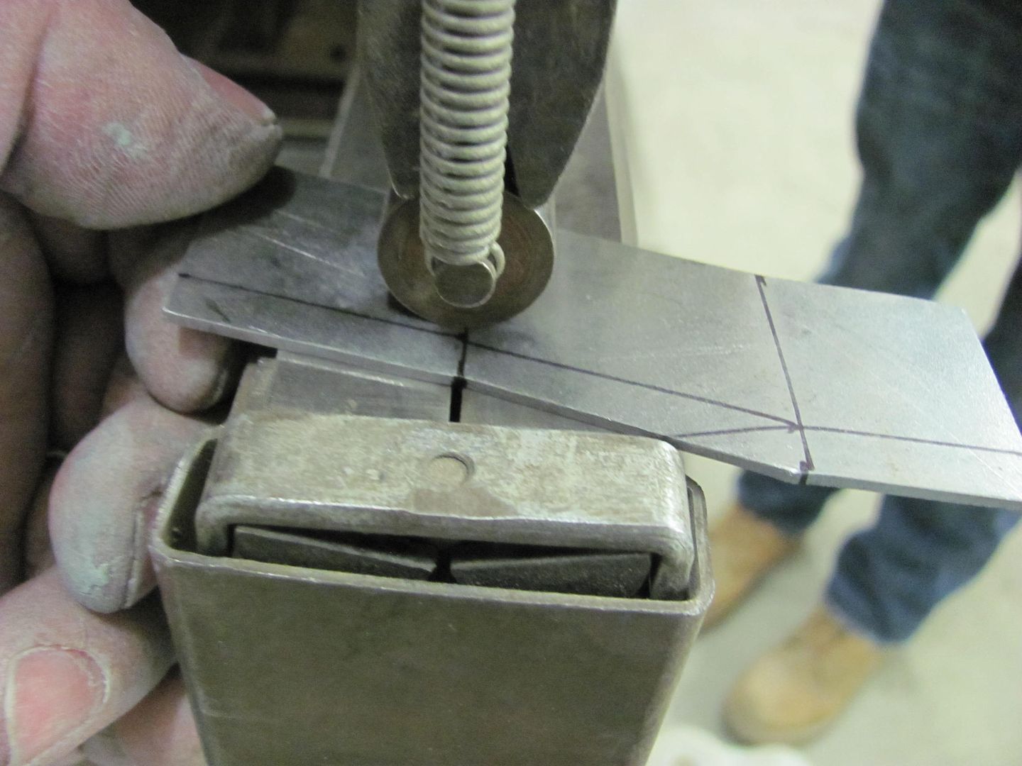
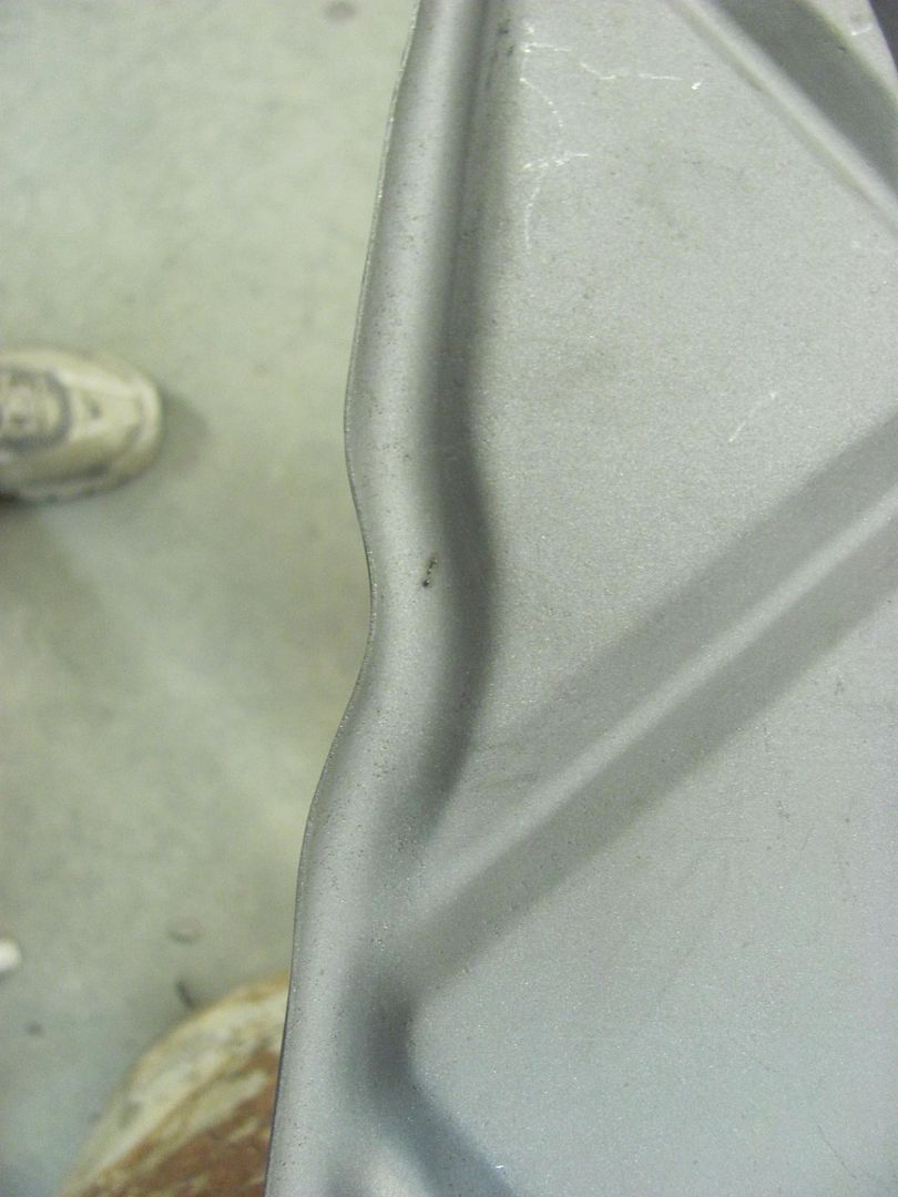
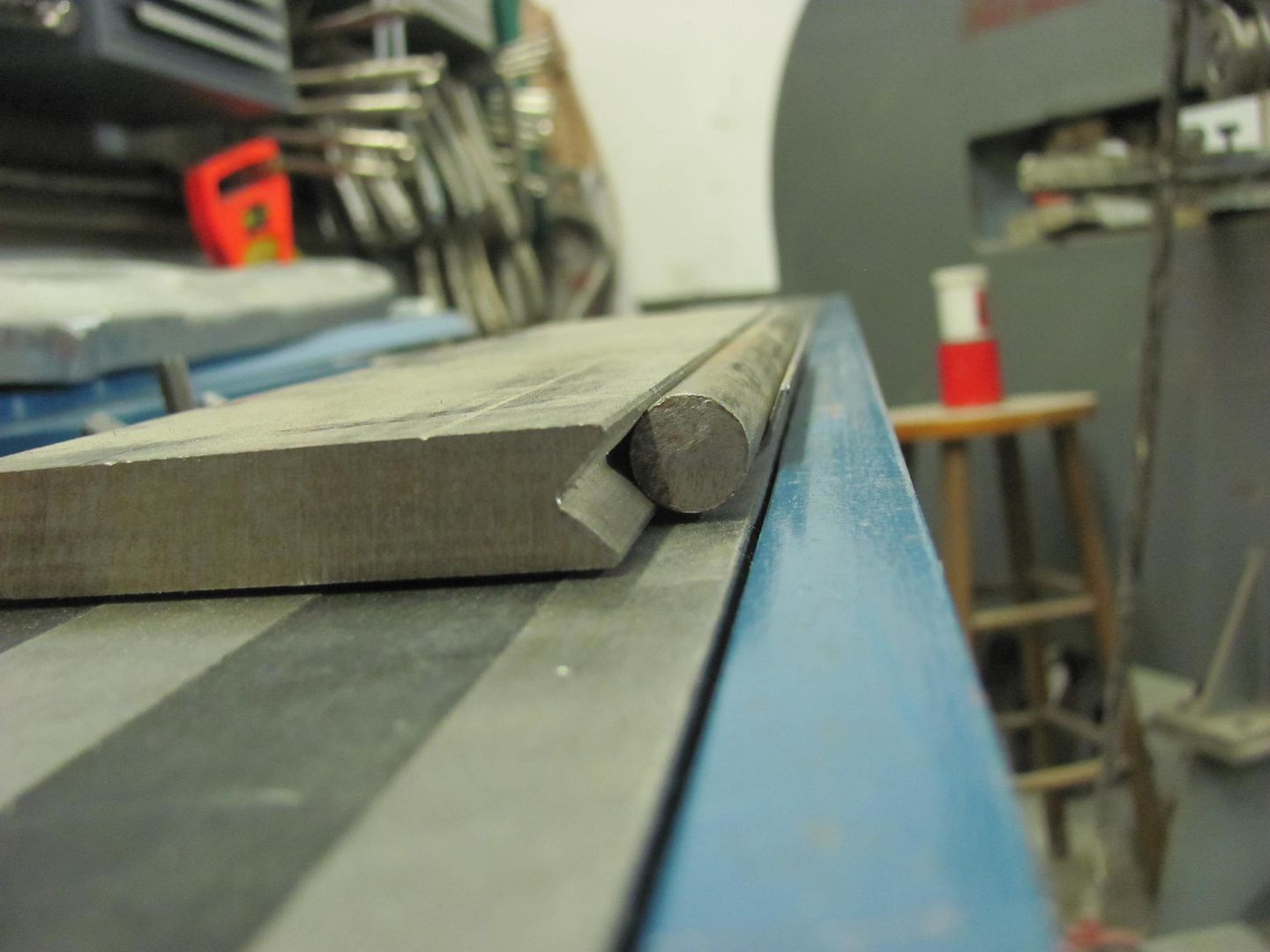
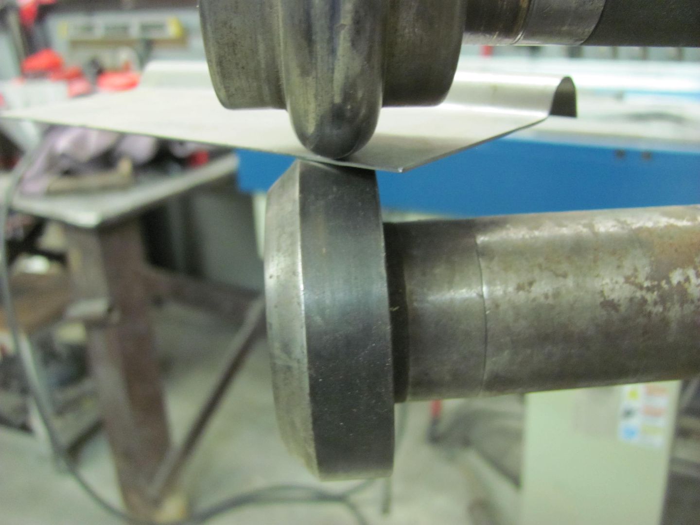
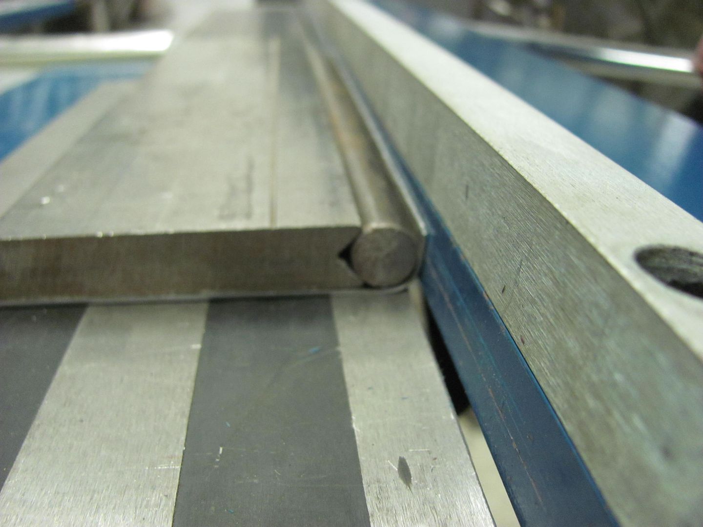
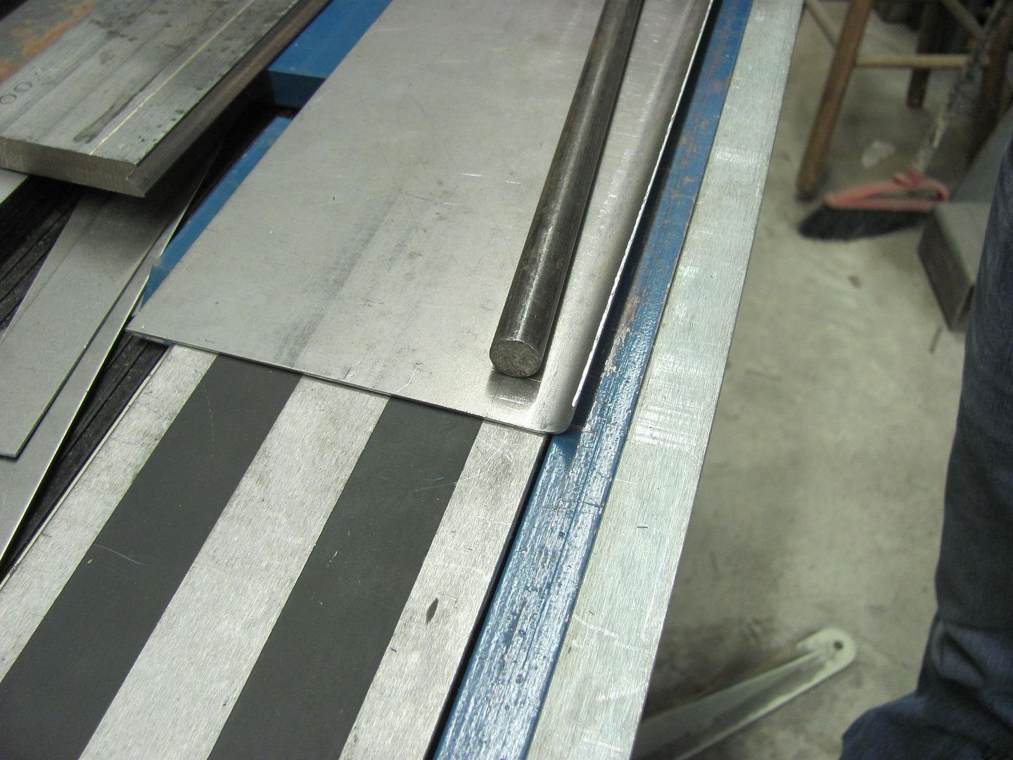
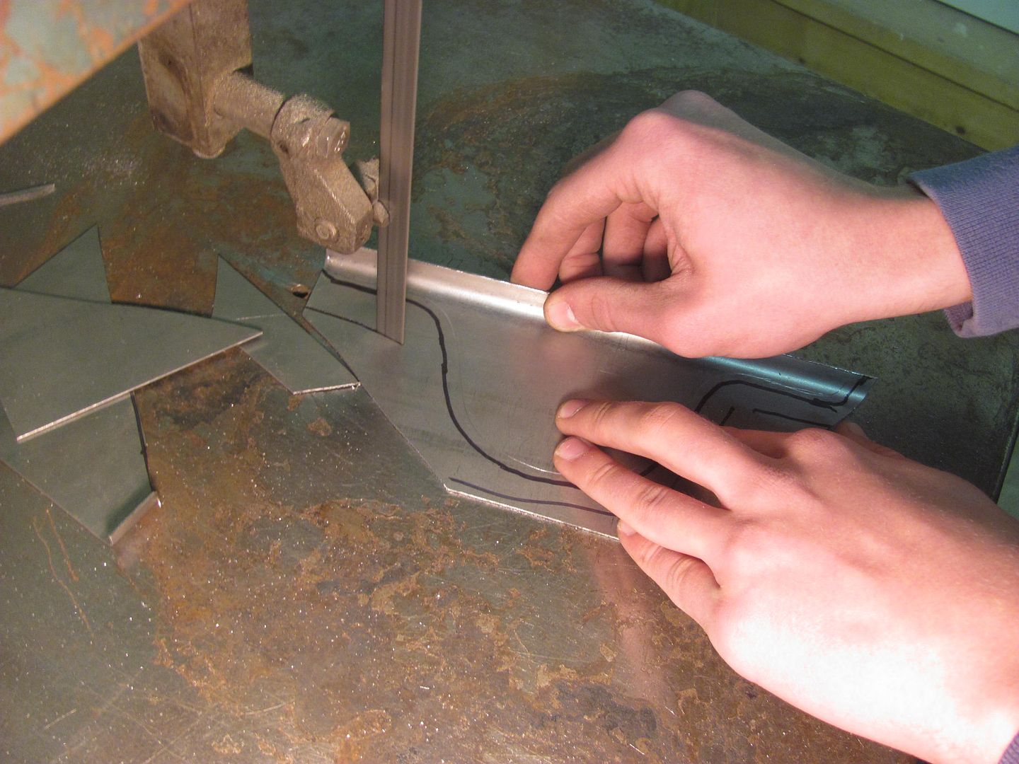
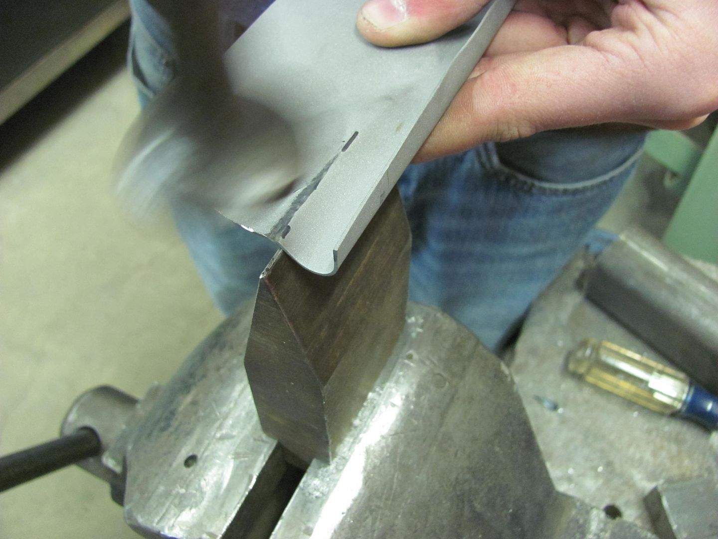
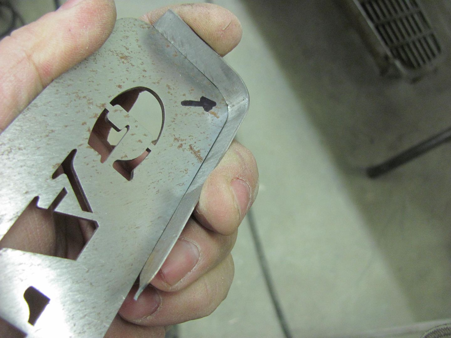
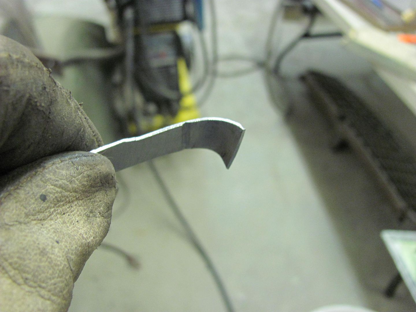
Radius patch is bent using roll former dies in the Diacro press brake and checked to the radius gauge...


Picture1852.jpg


Picture1850.jpg


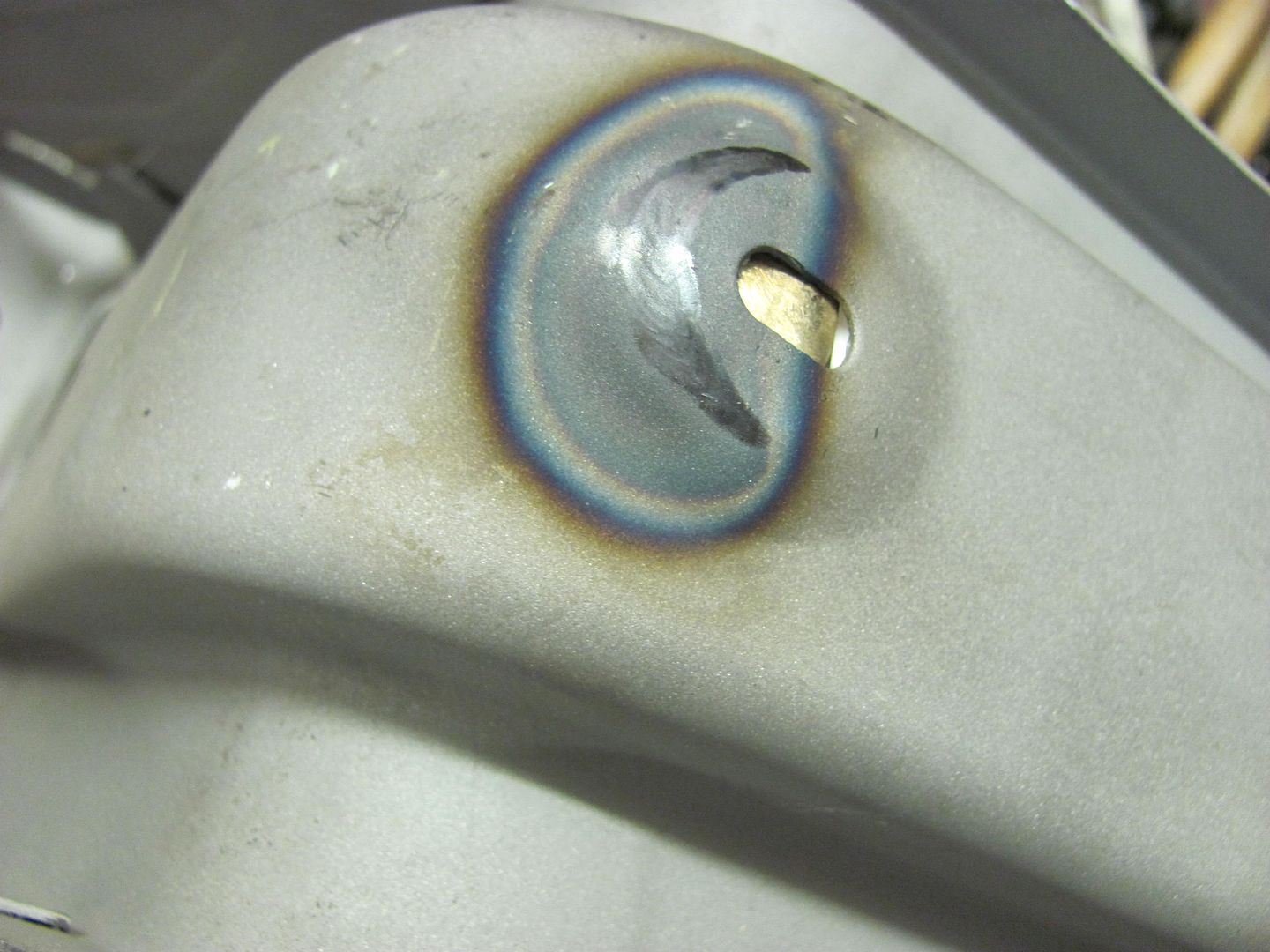
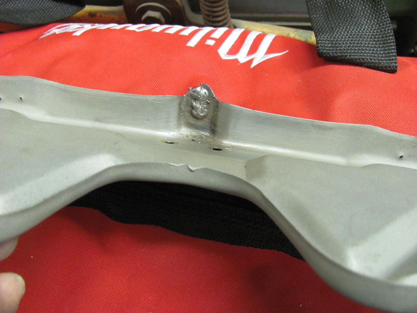
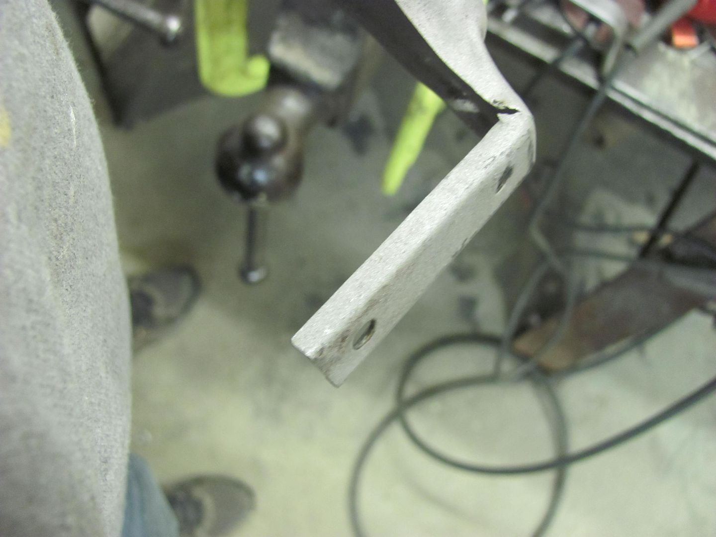
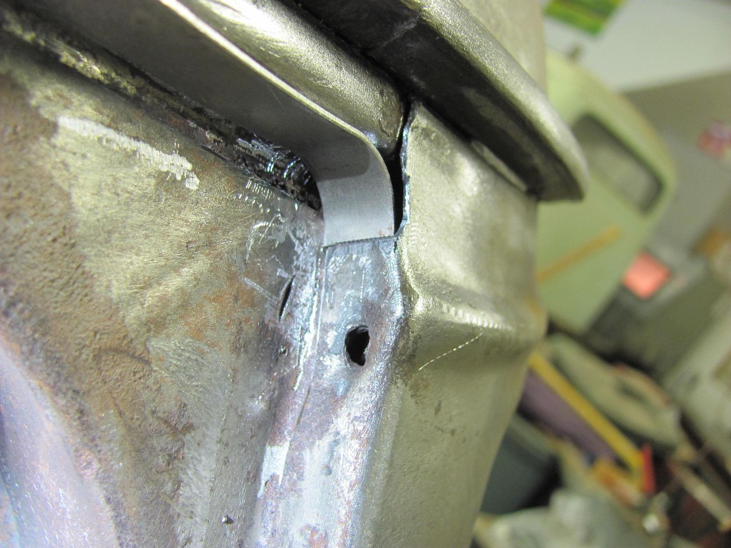
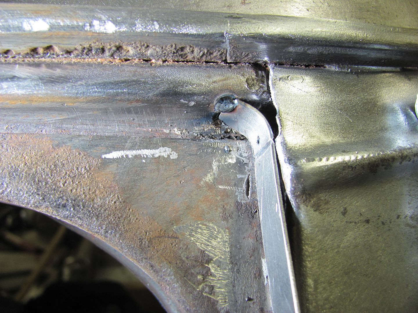
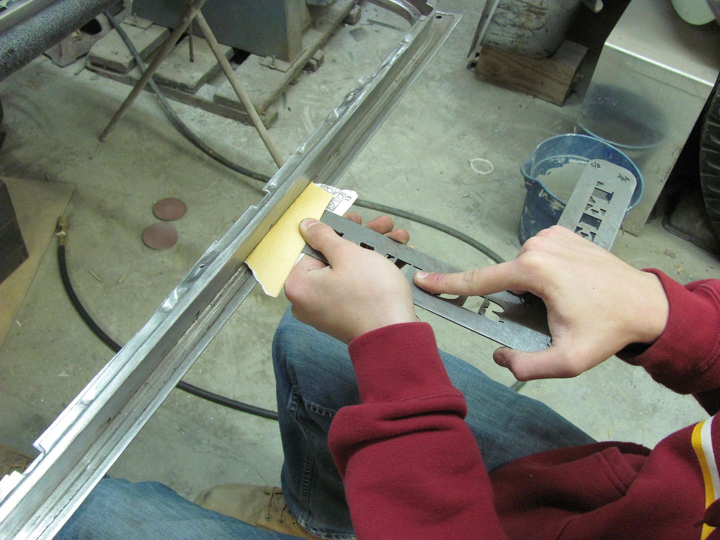
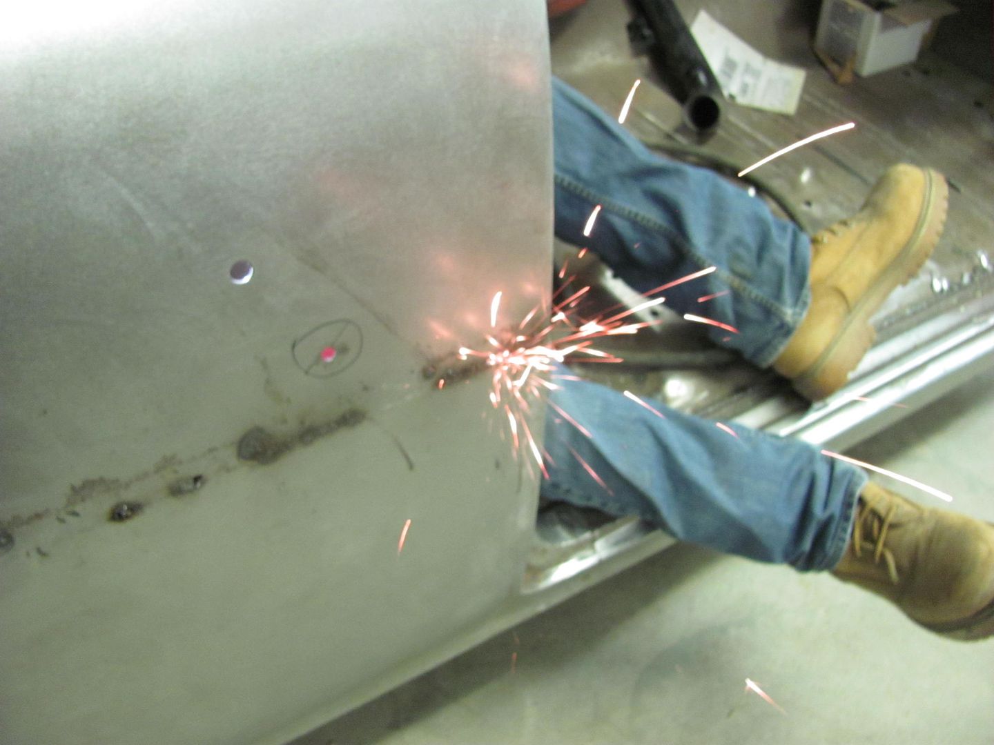
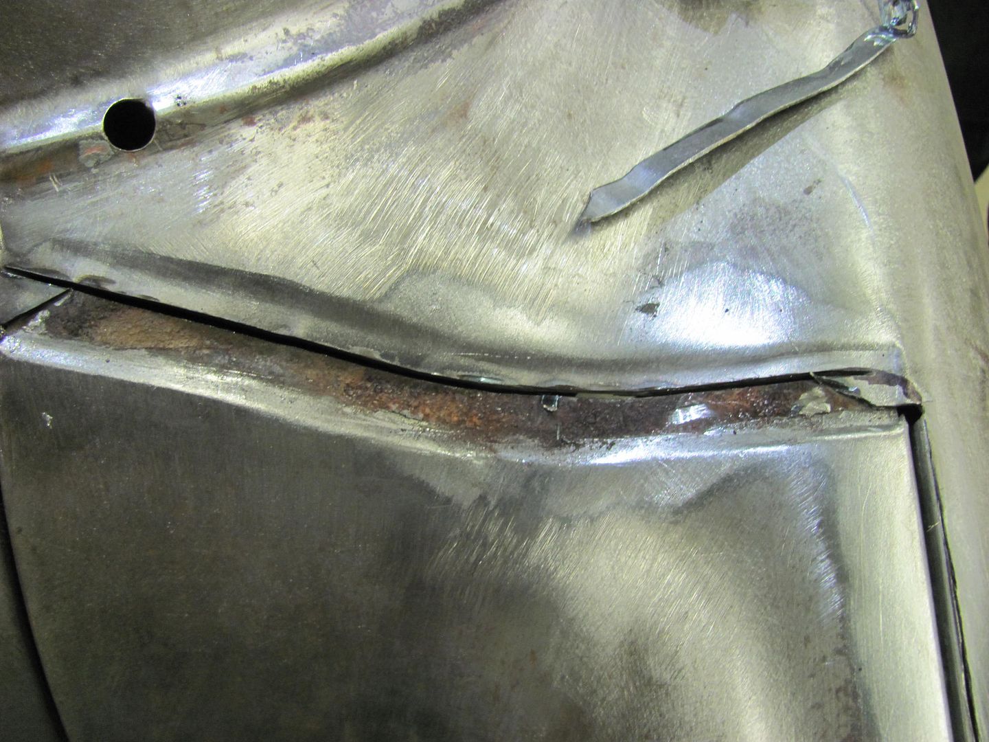
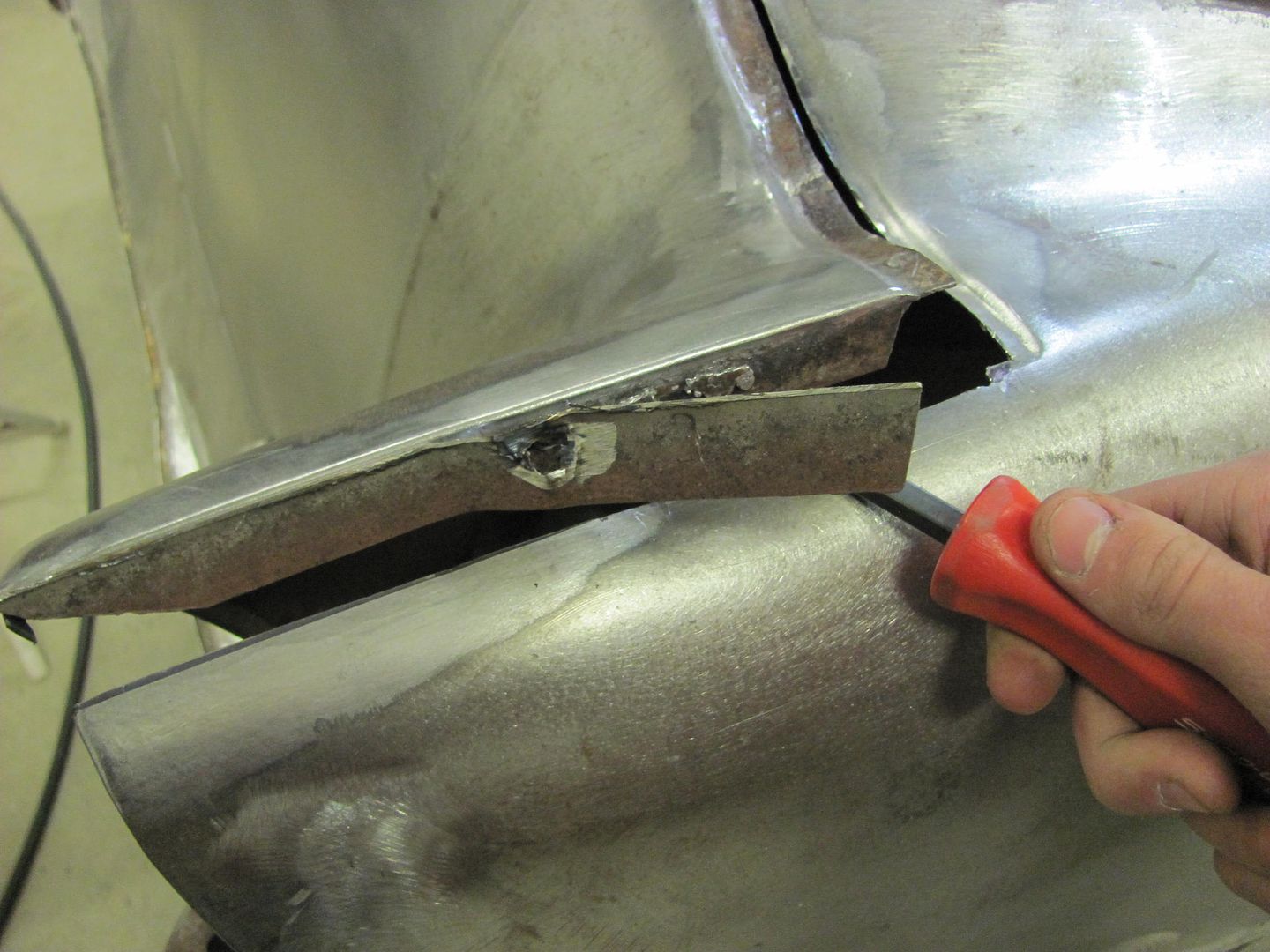
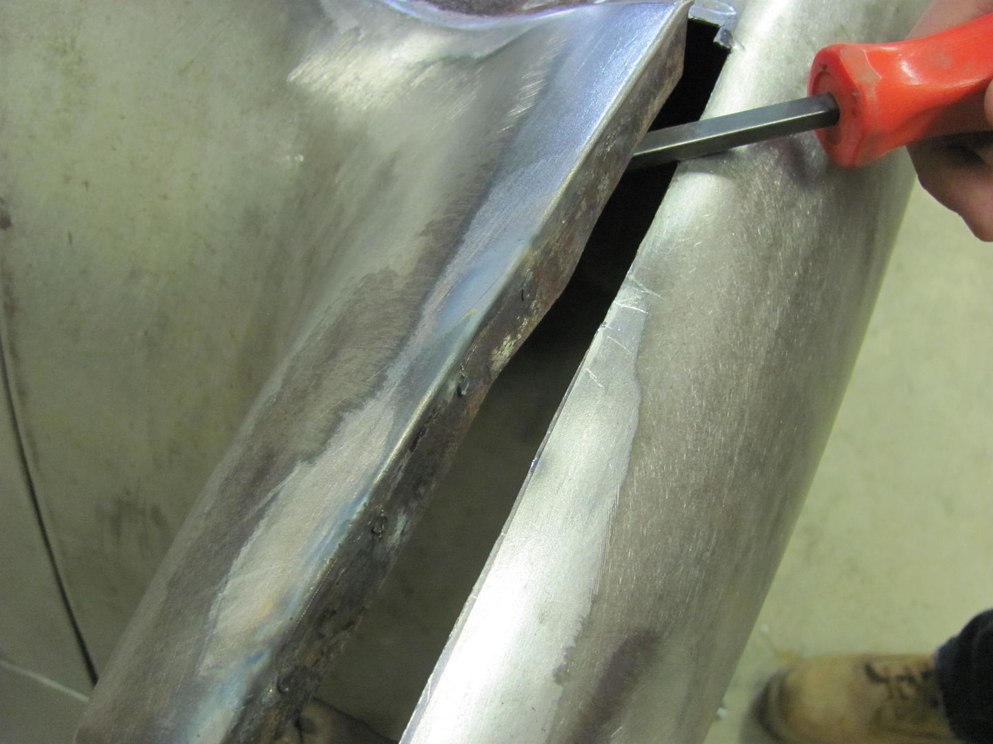
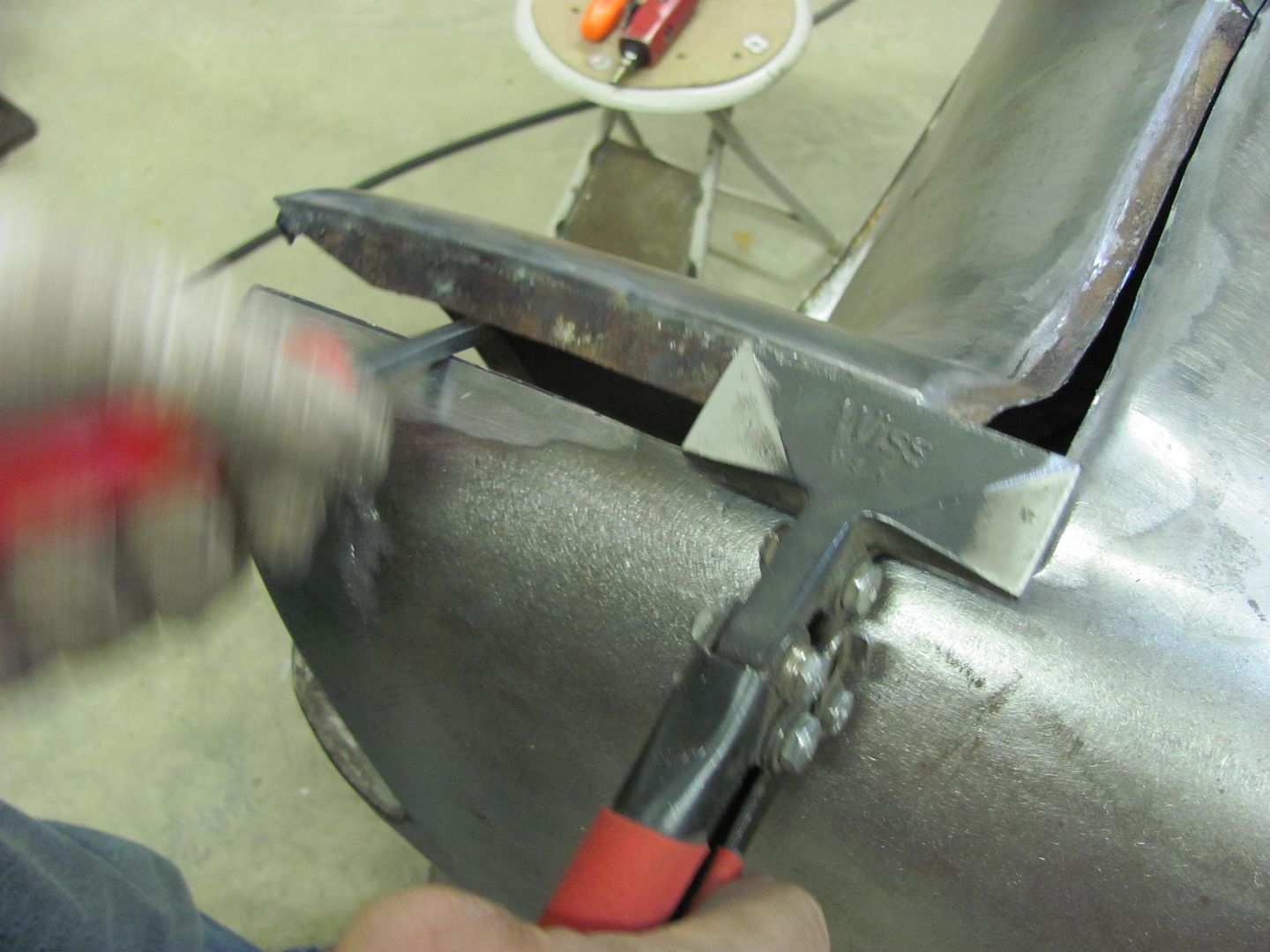
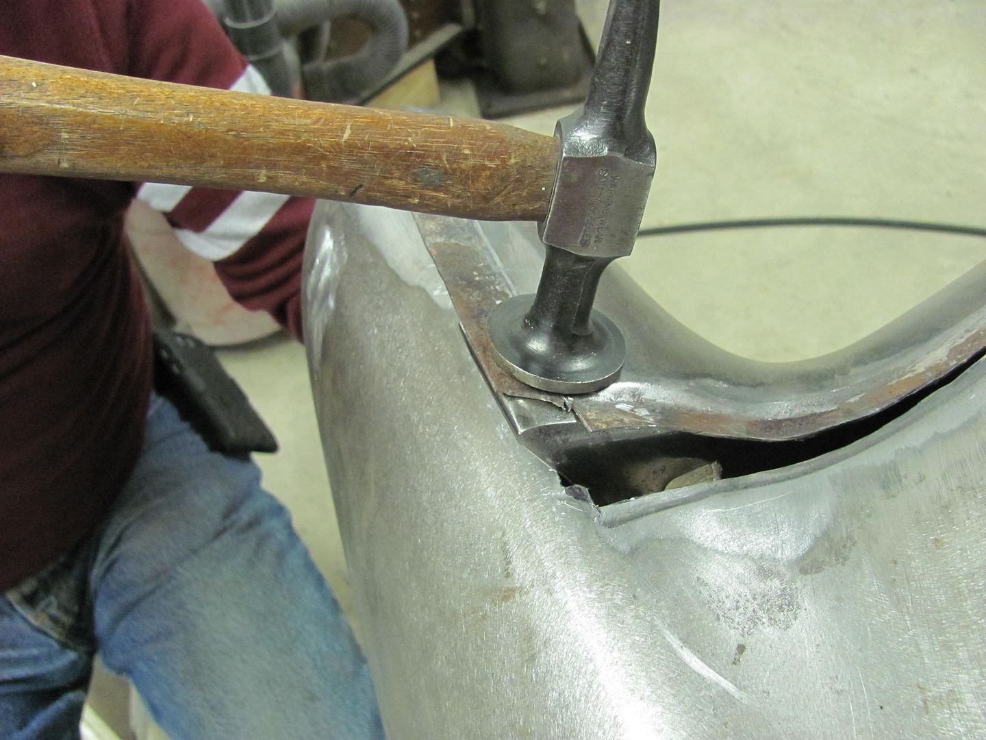
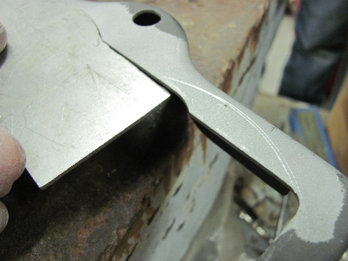
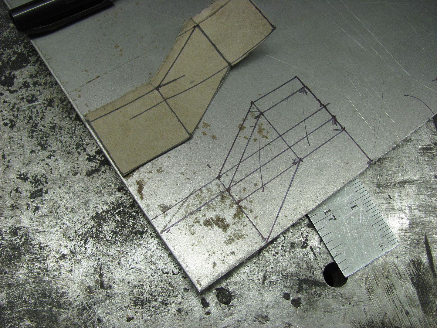
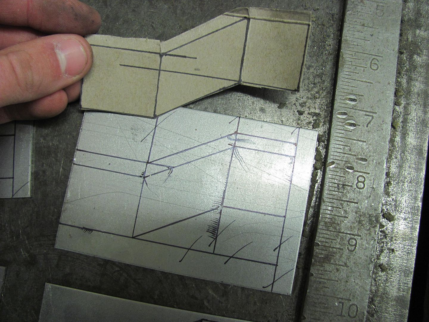
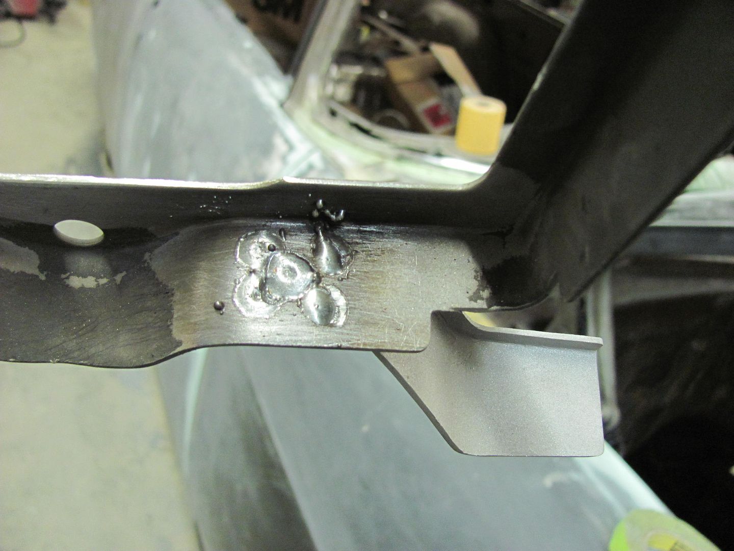
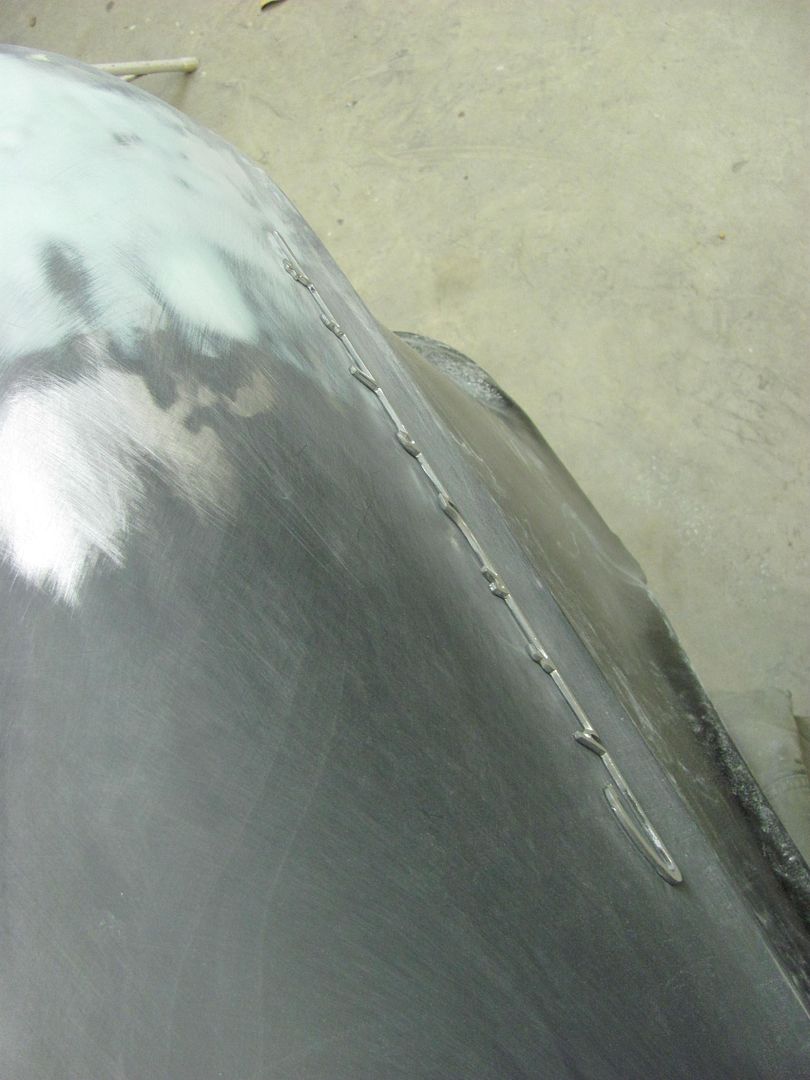
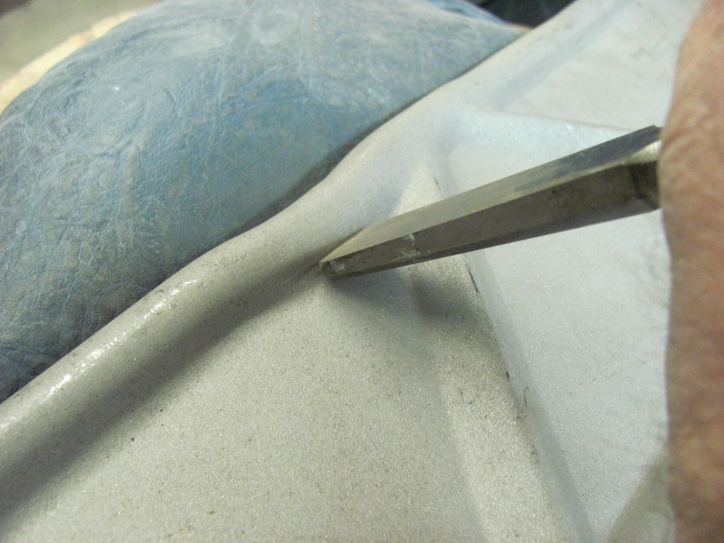
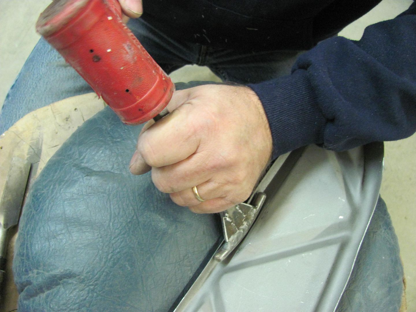
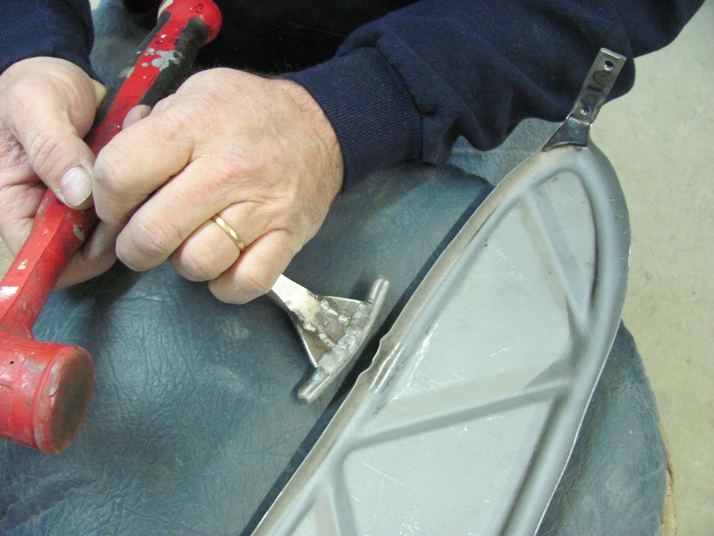
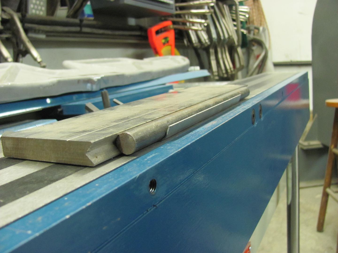
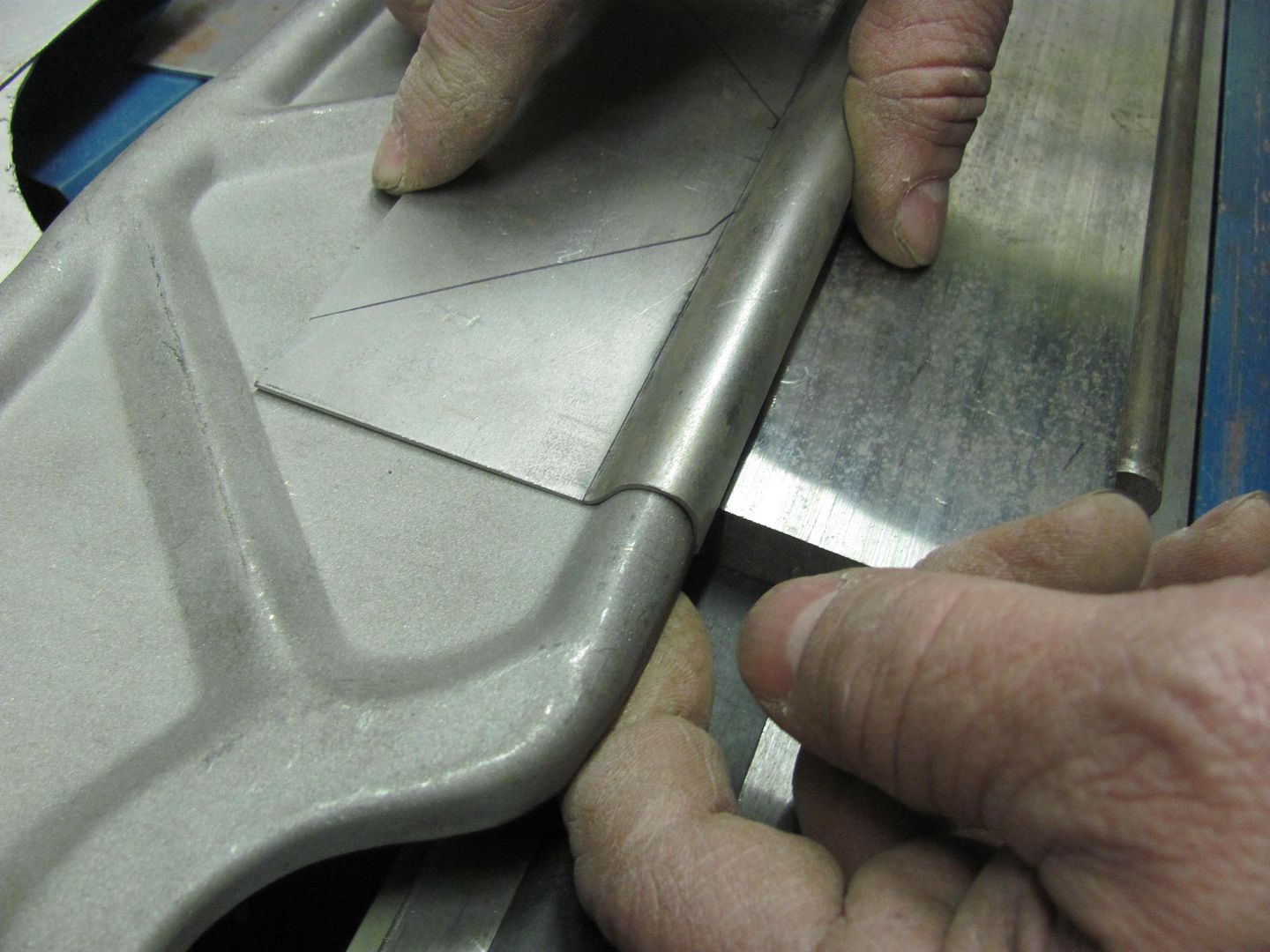
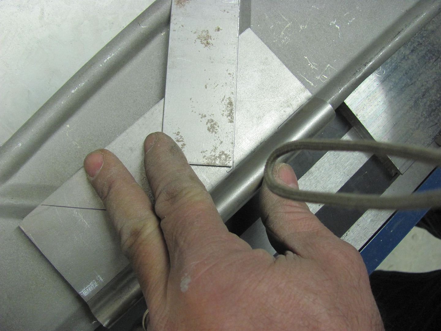
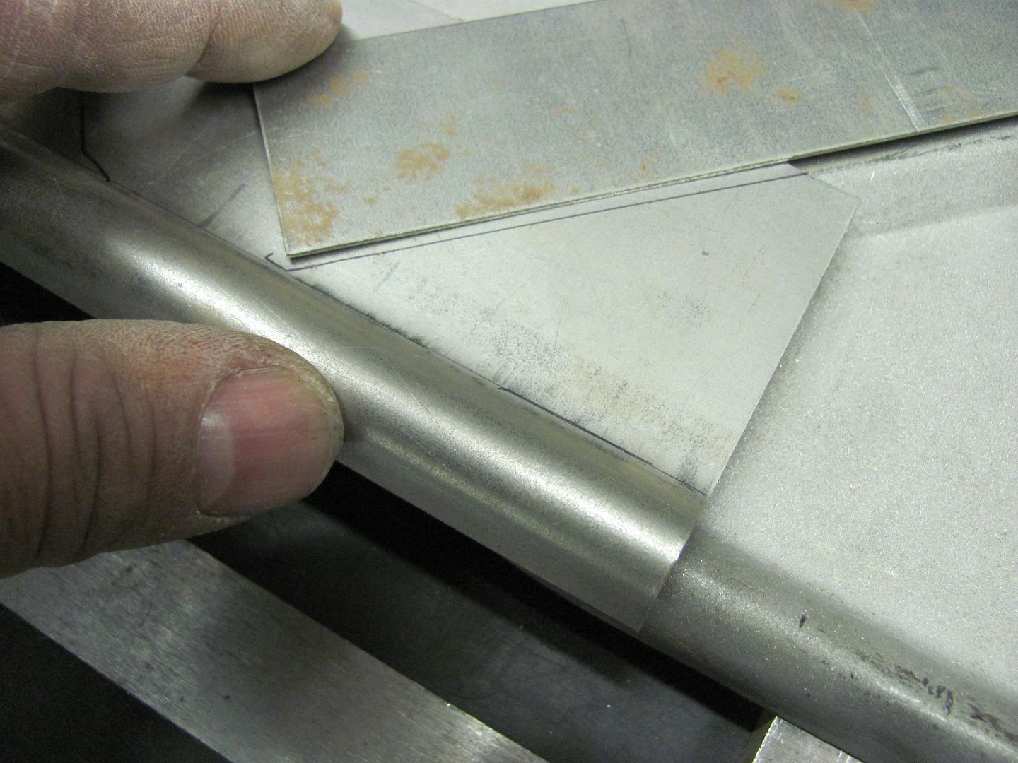
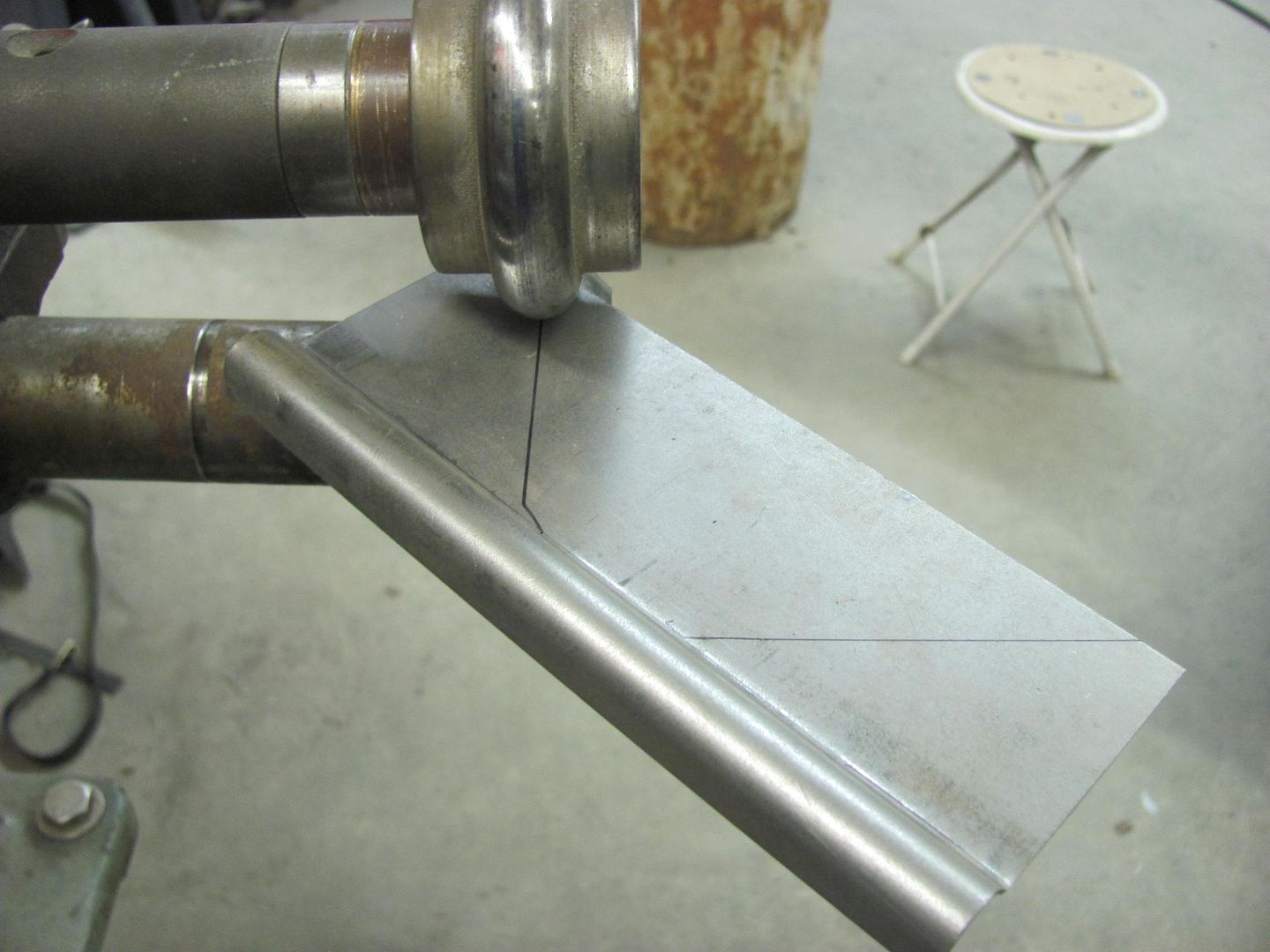
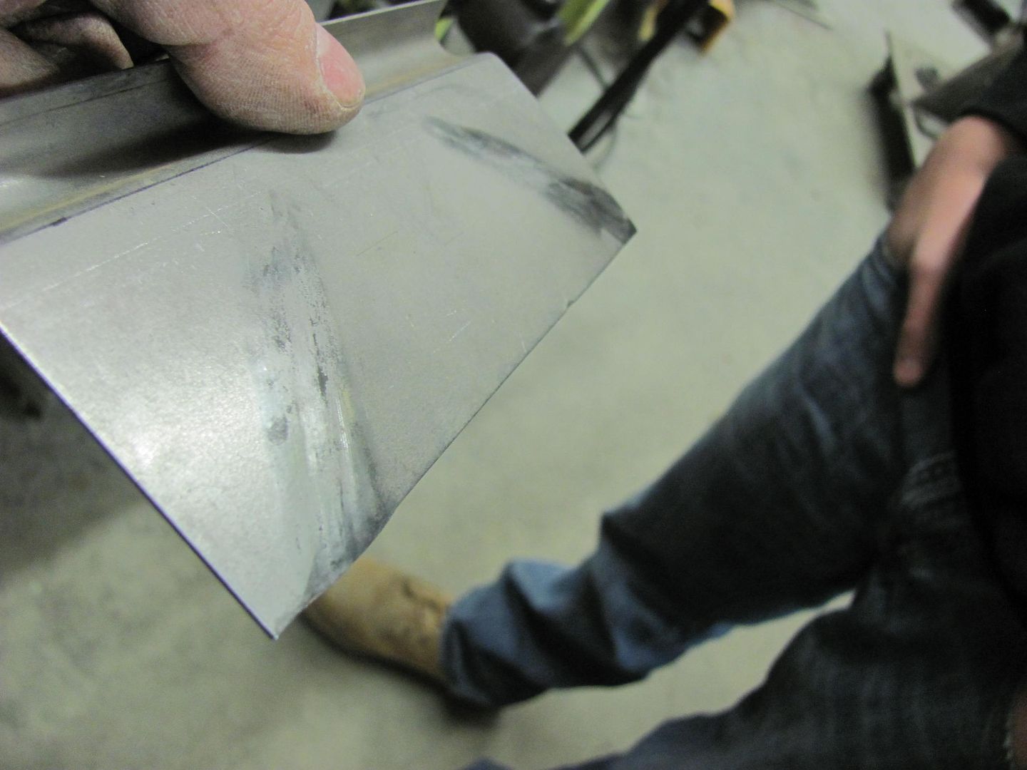
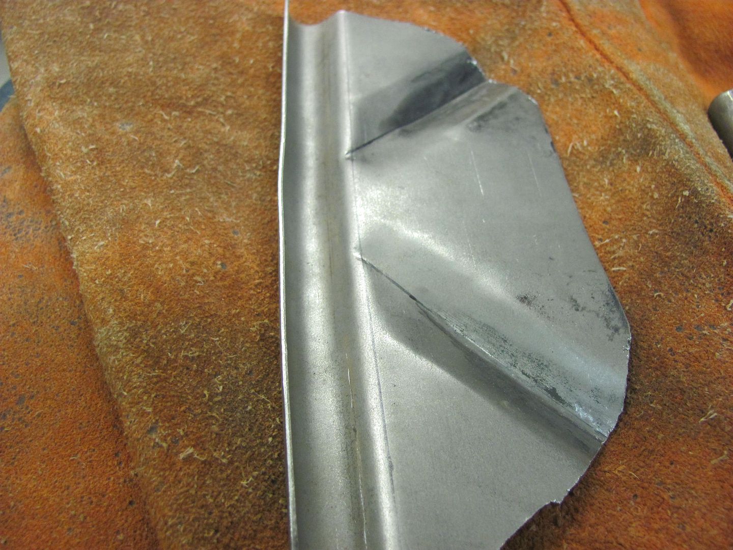
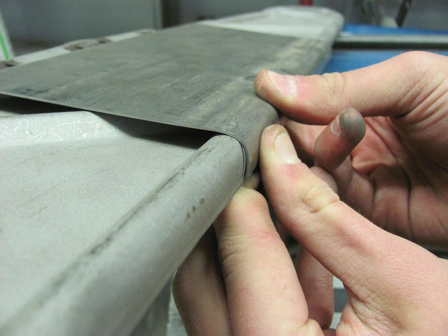
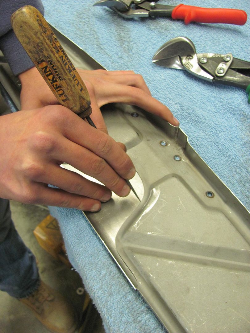
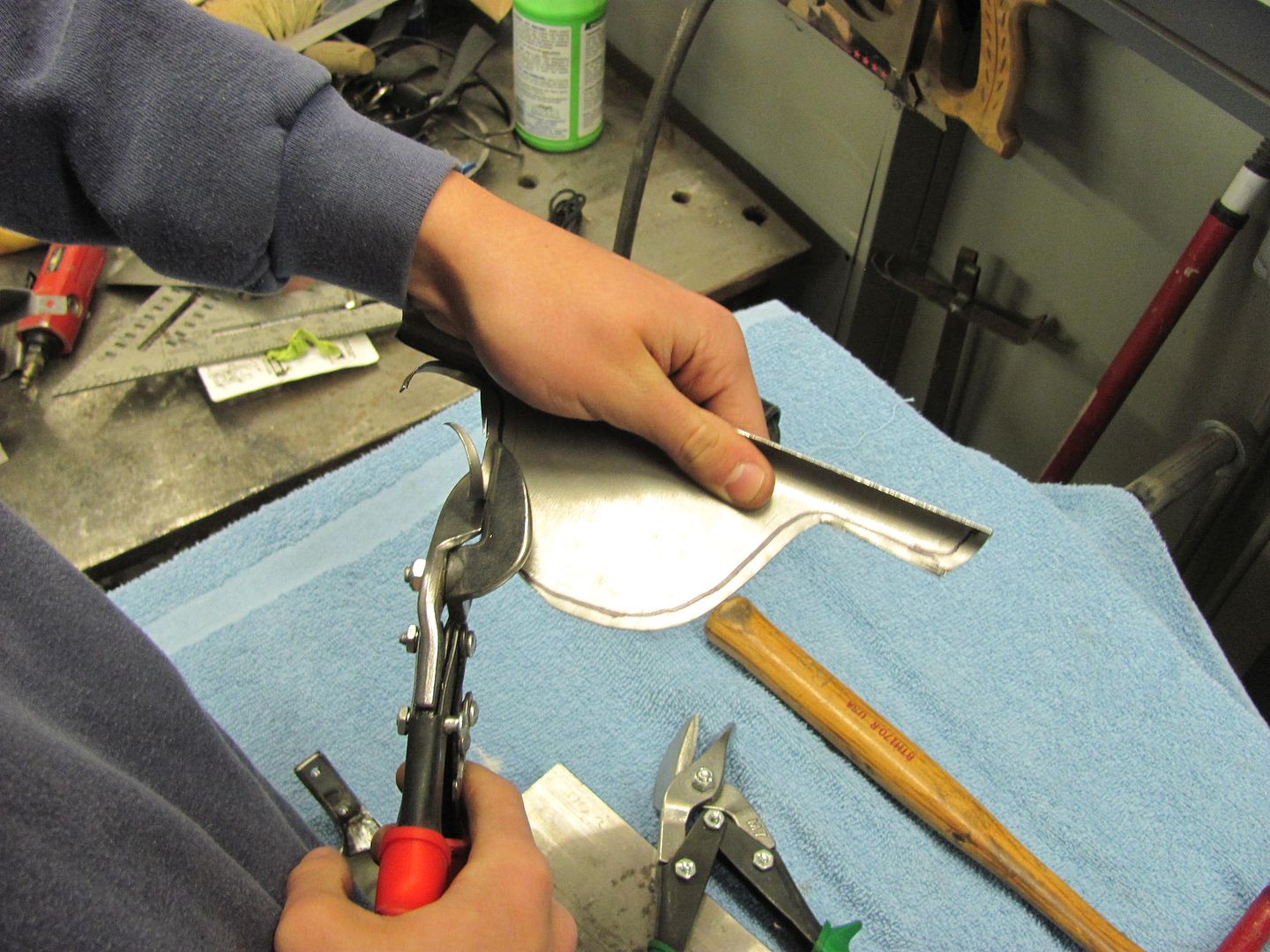
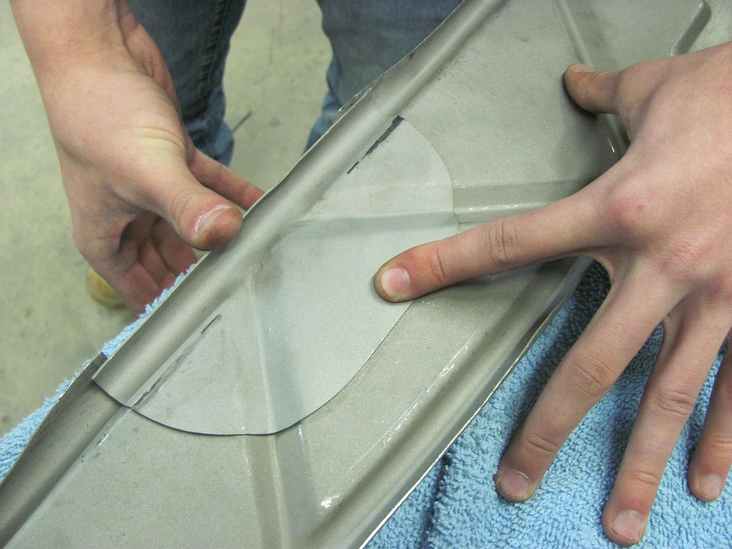
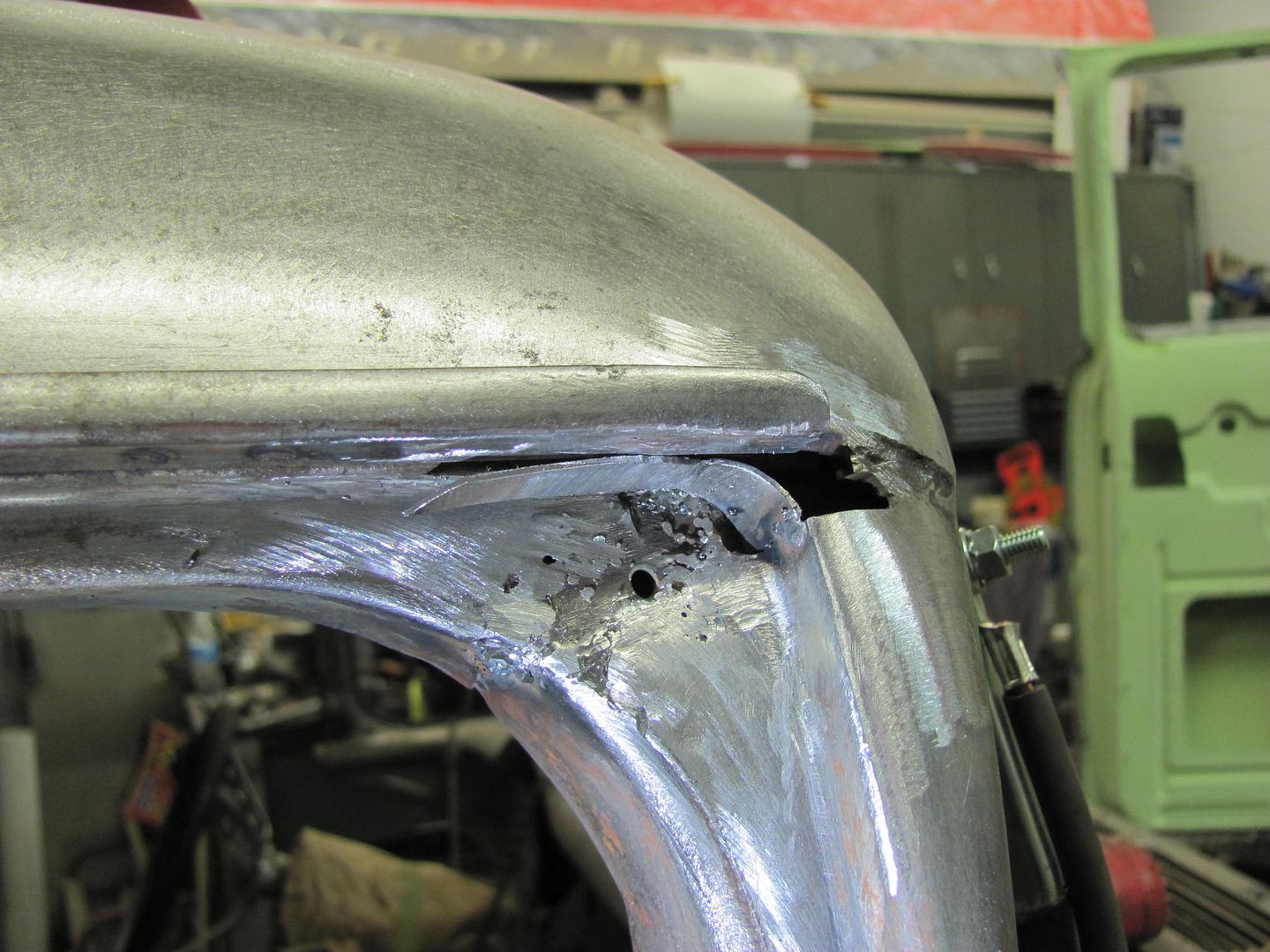
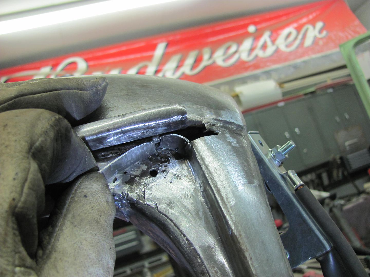
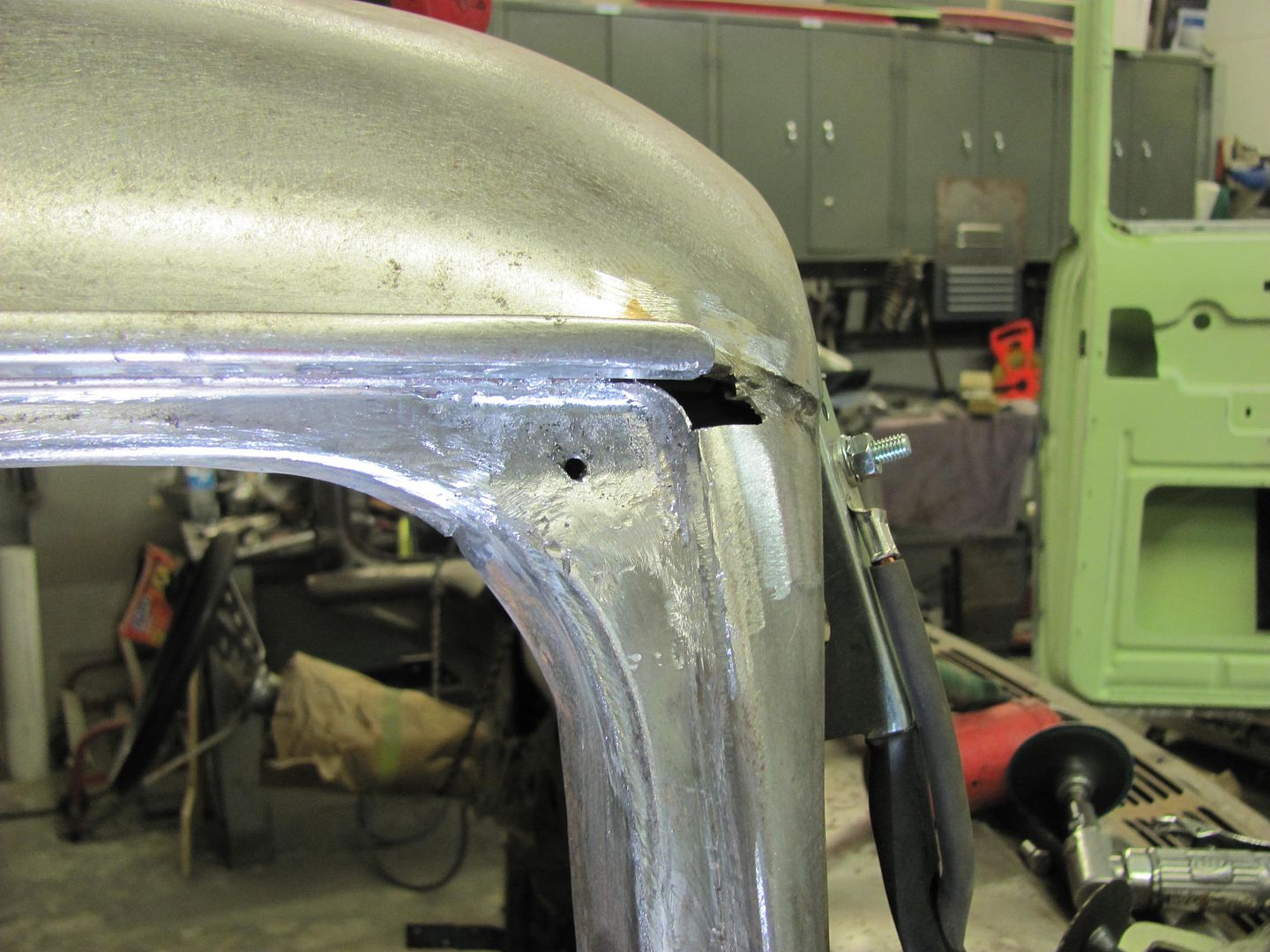
The patch is trimmed for the fit to the A-pillar, and a horizontal tail is left to have something to hold on to while tacking in place. A score is added using the cutoff wheel so the excess can be snapped off after tacking...


Picture1857.jpg


Picture1853.jpg


Picture1854.jpg


Picture1855.jpg


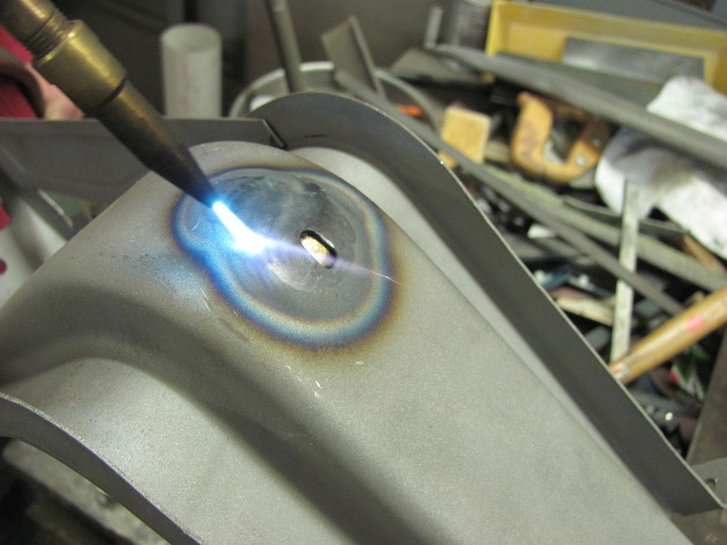
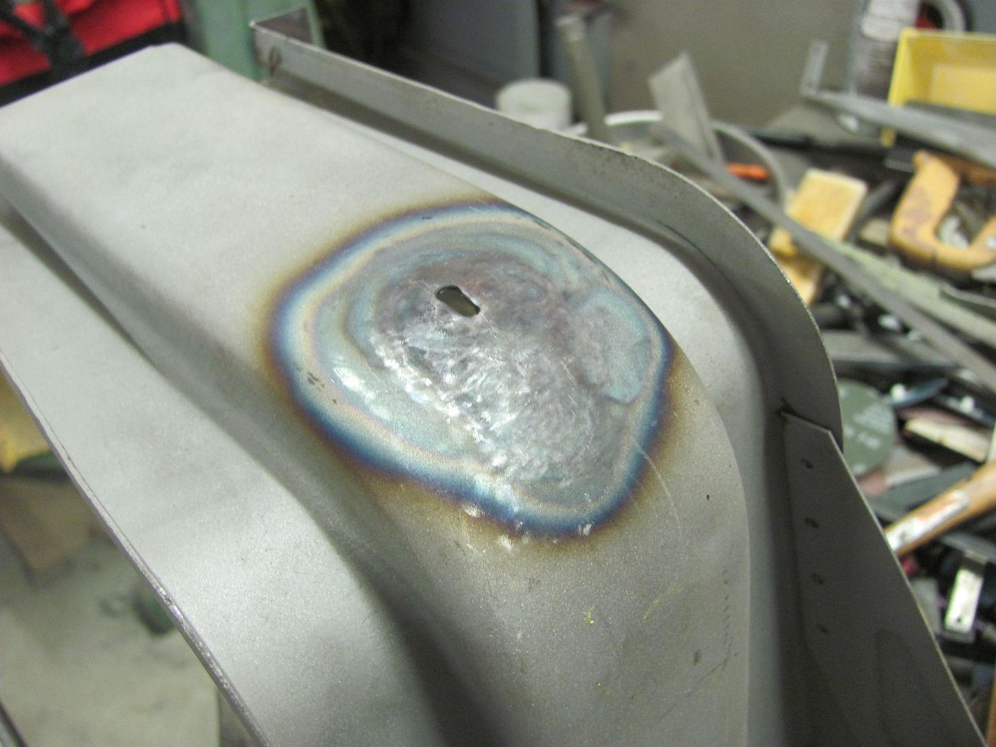
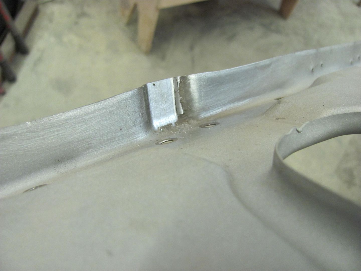
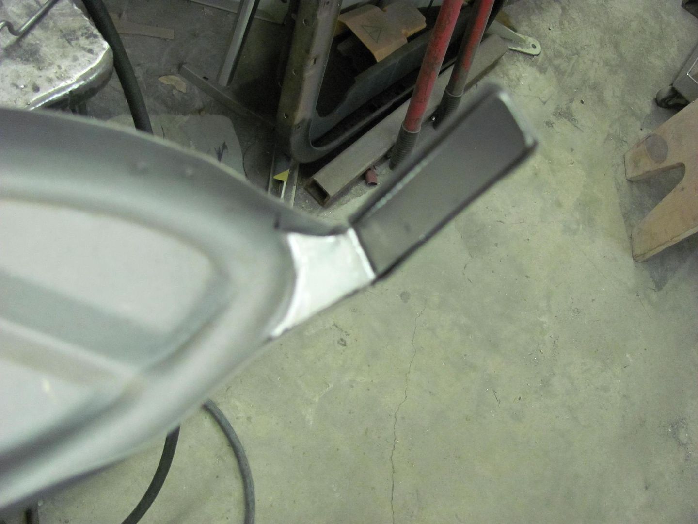
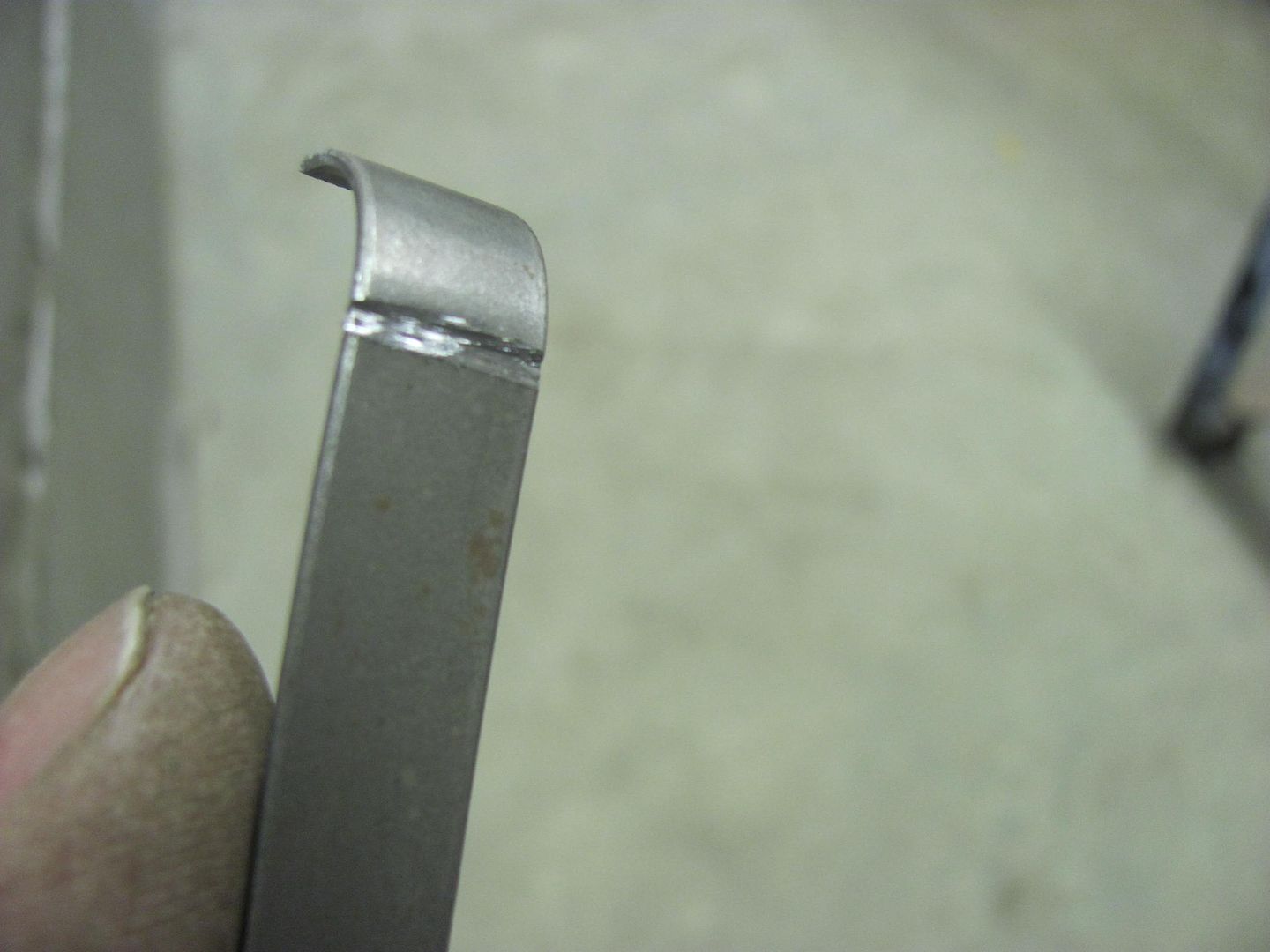
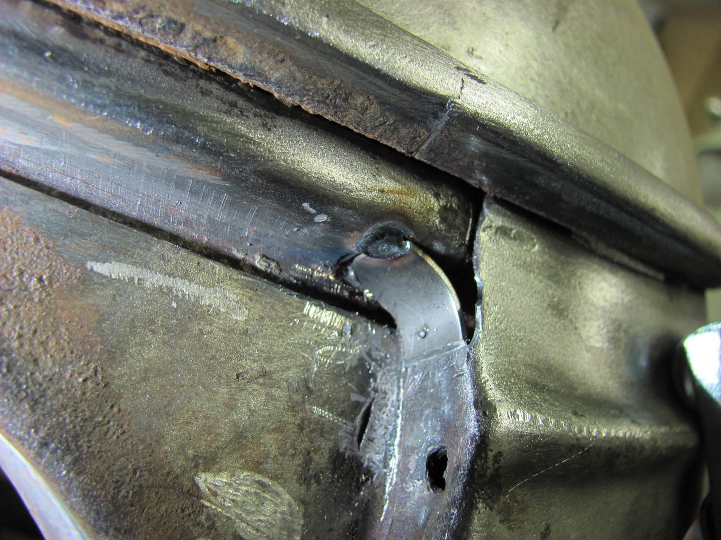
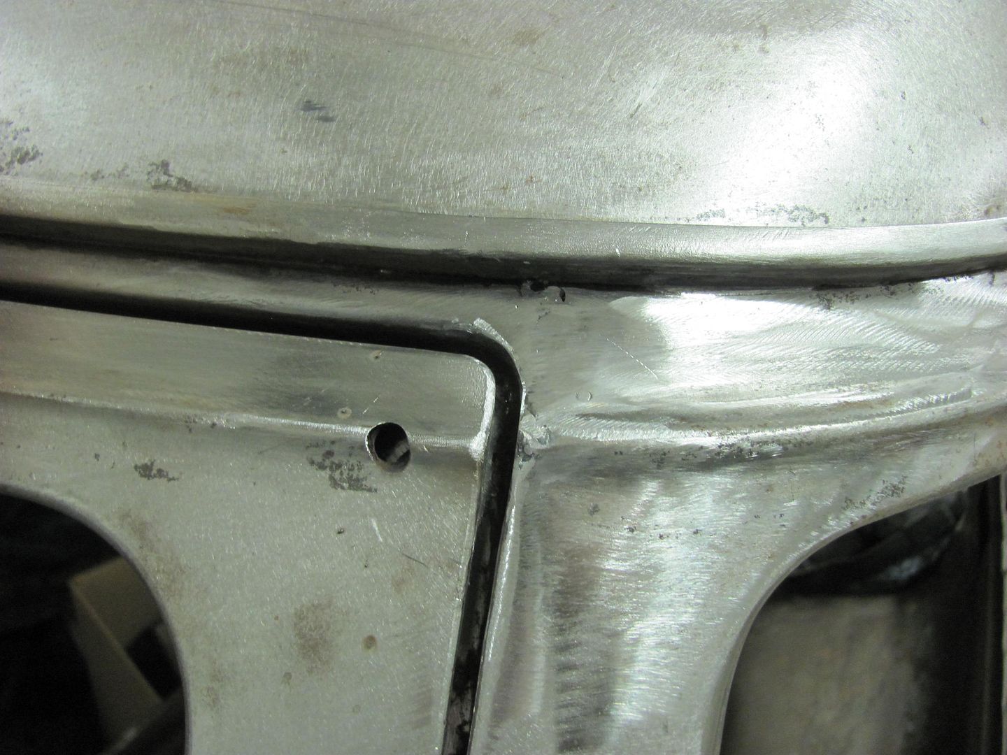
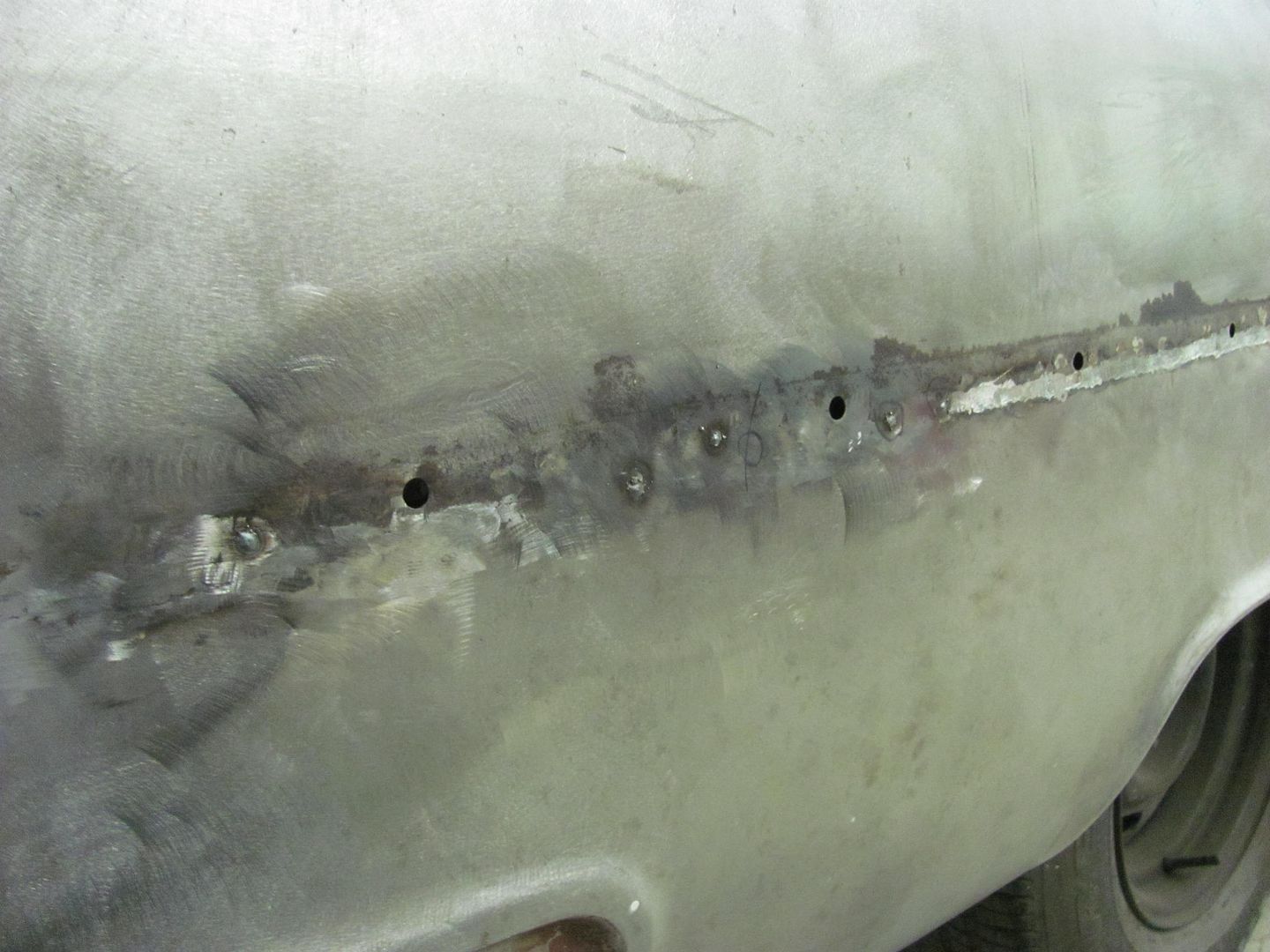
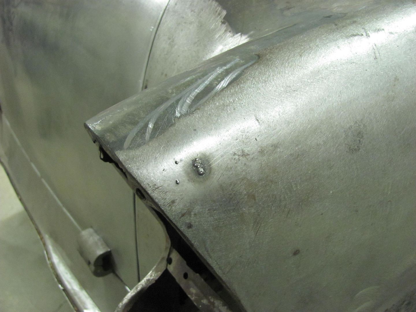
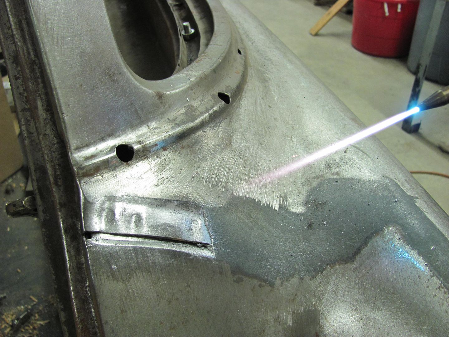
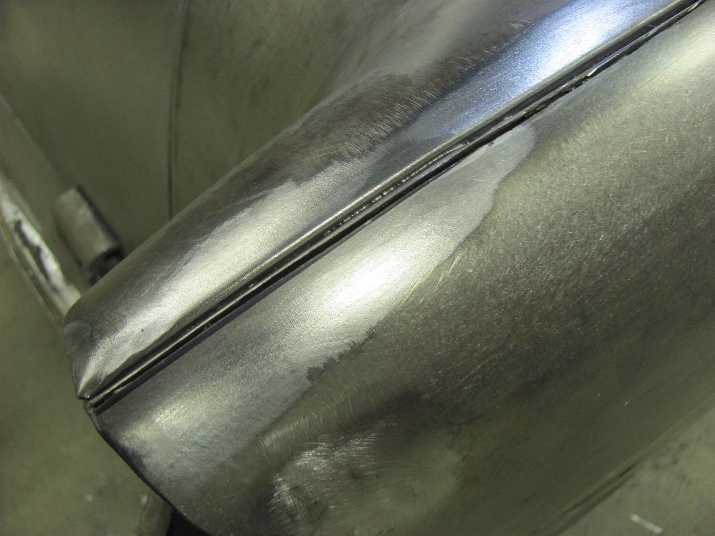
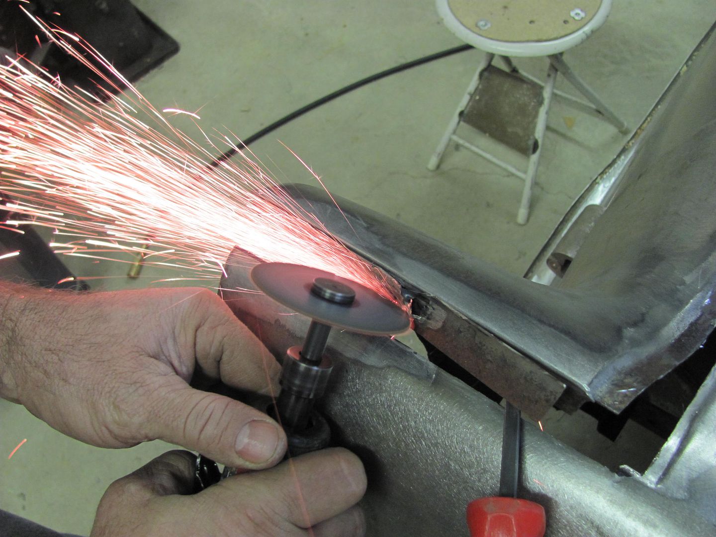
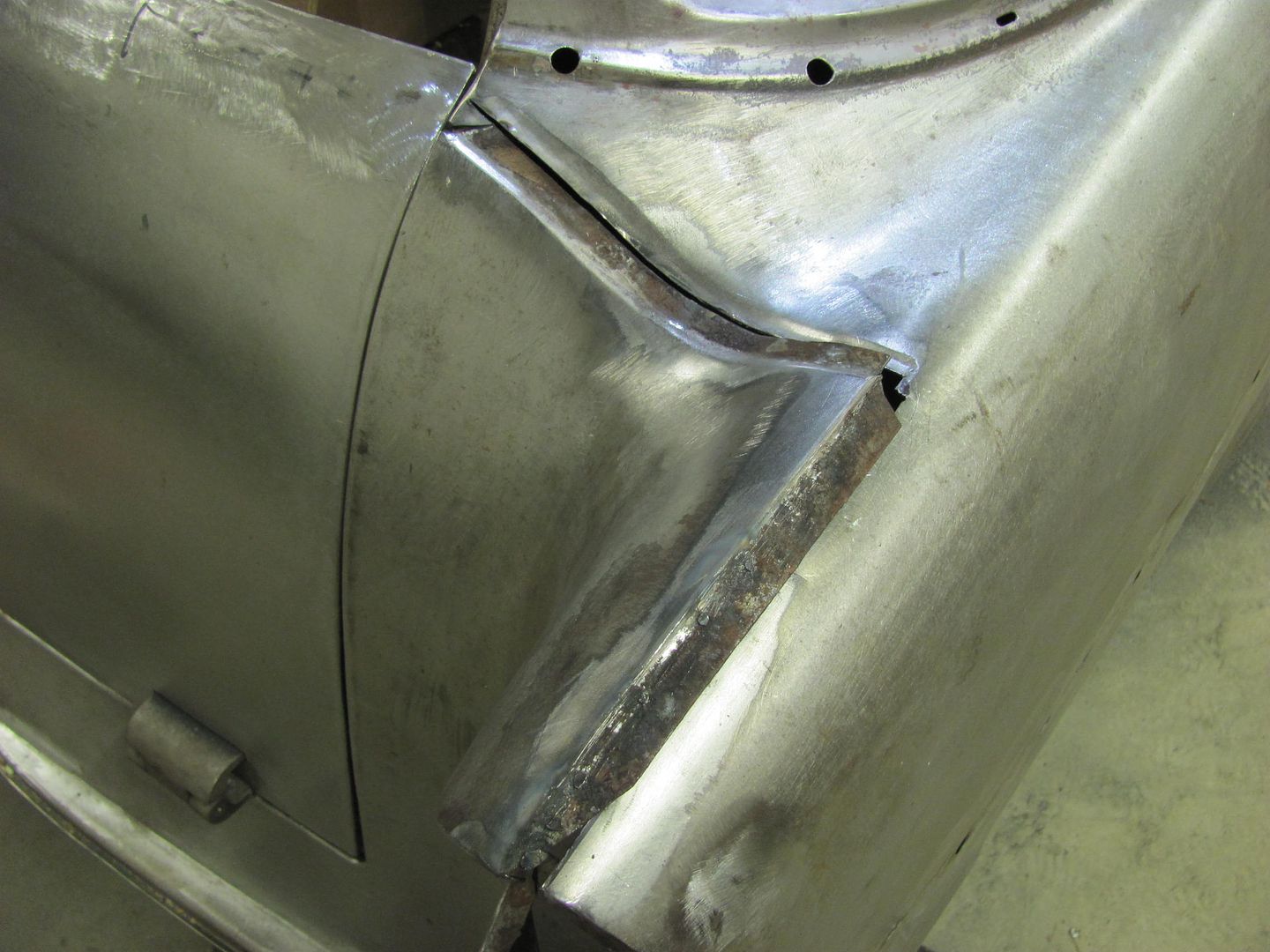
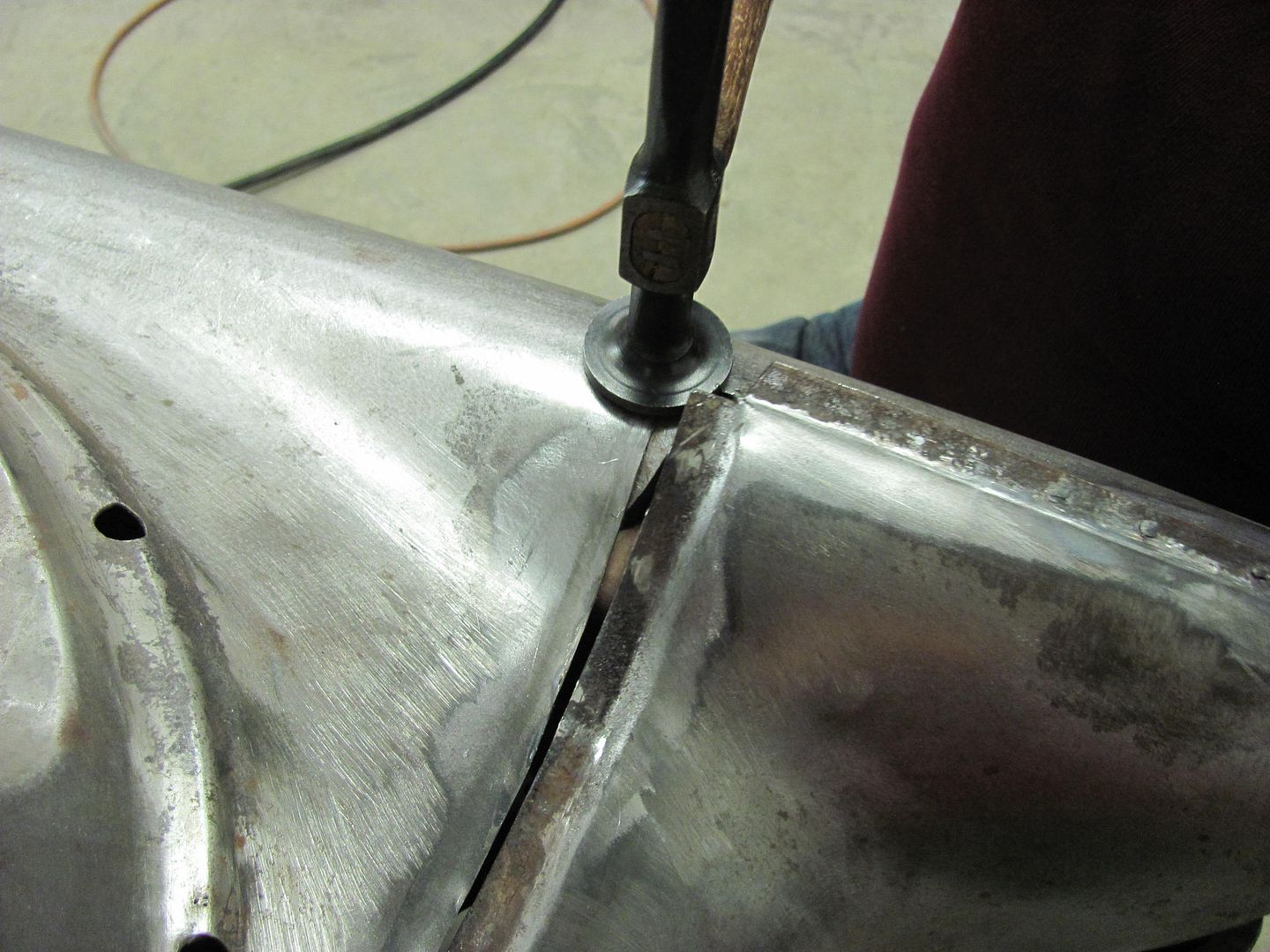
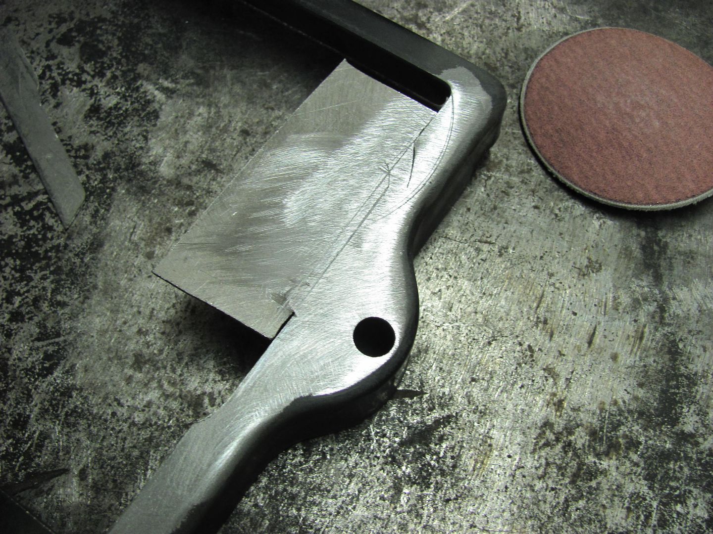
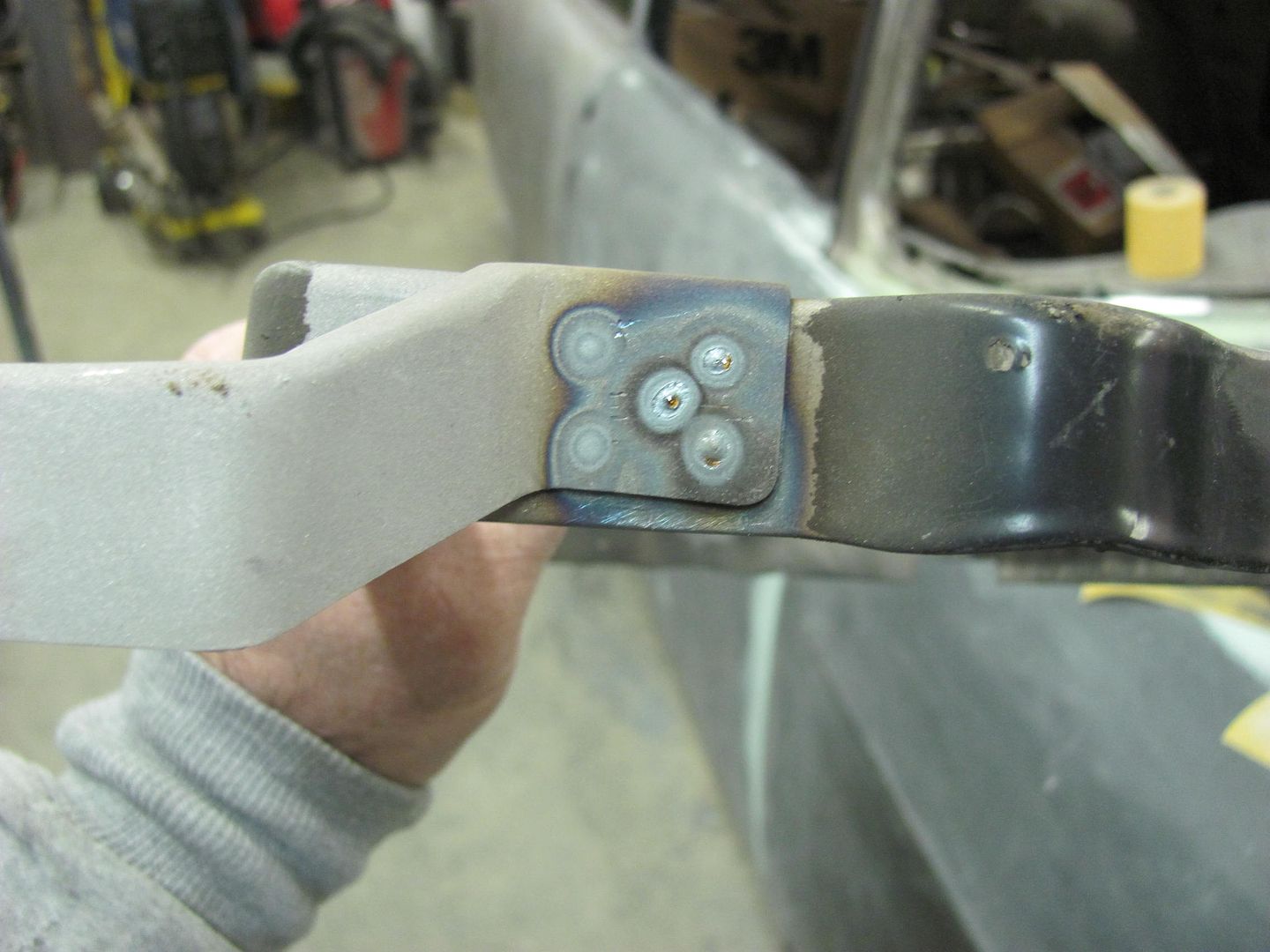
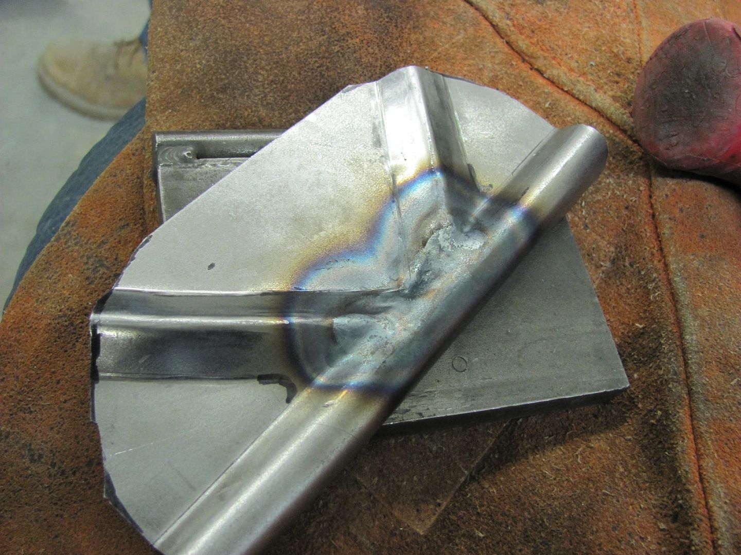
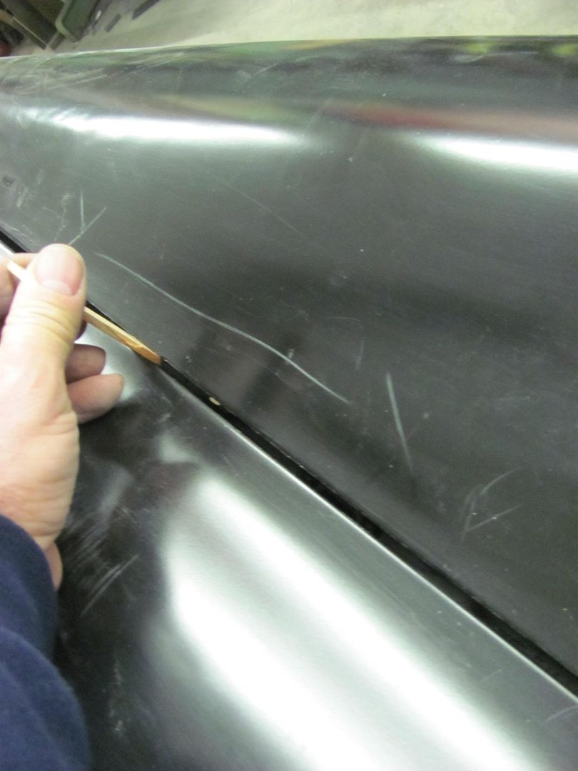
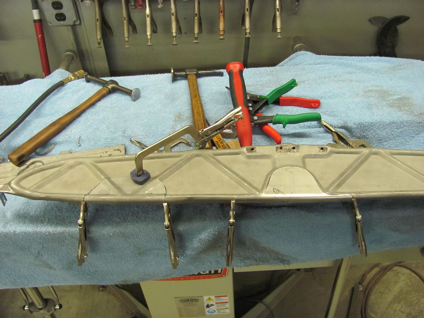
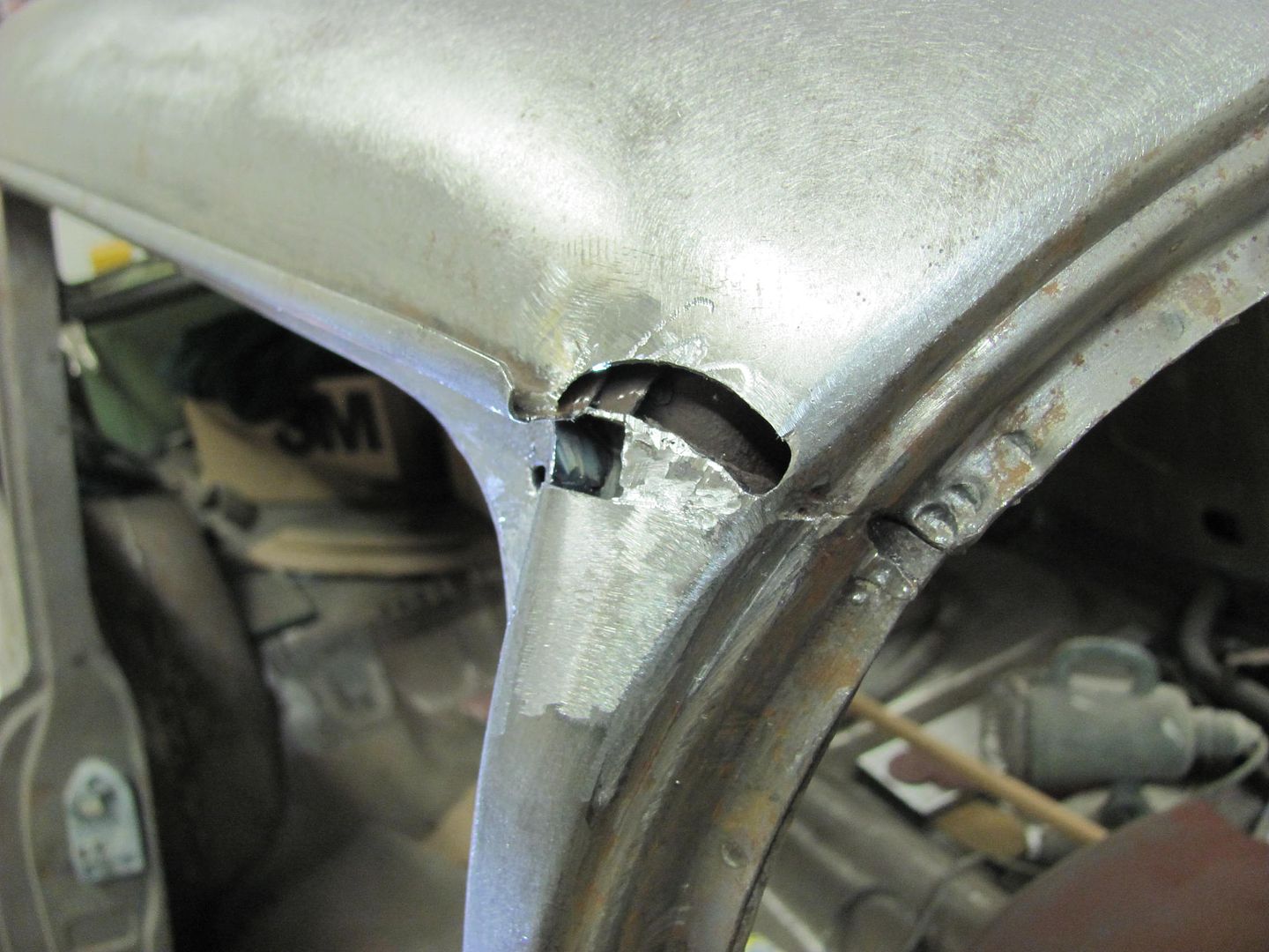
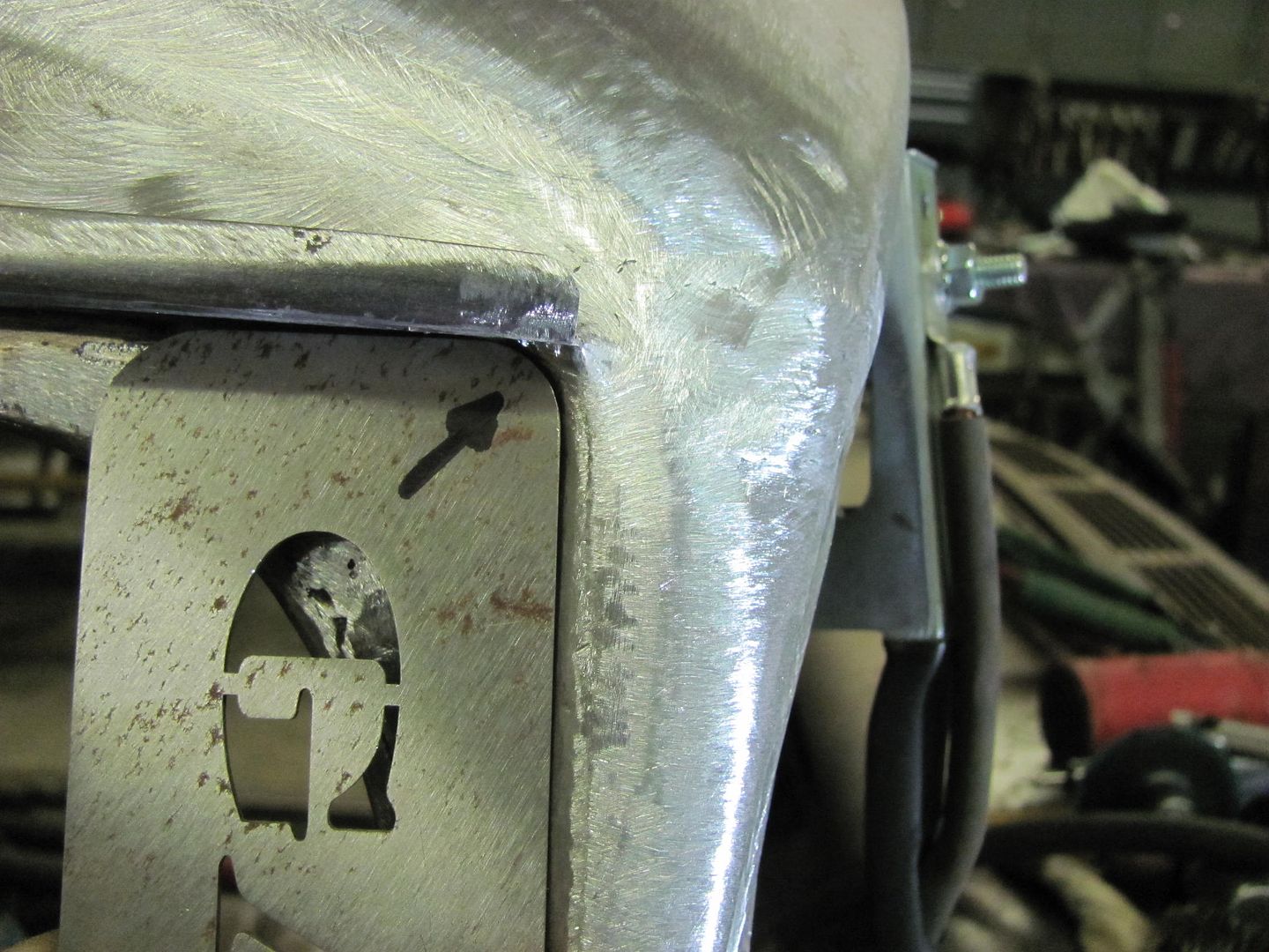
Welded and dressed..


Picture1858.jpg


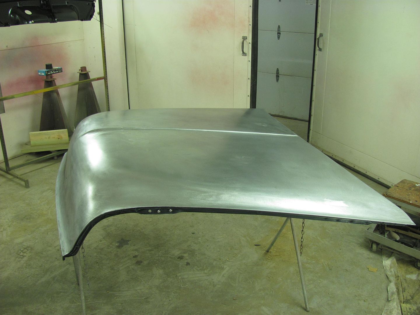
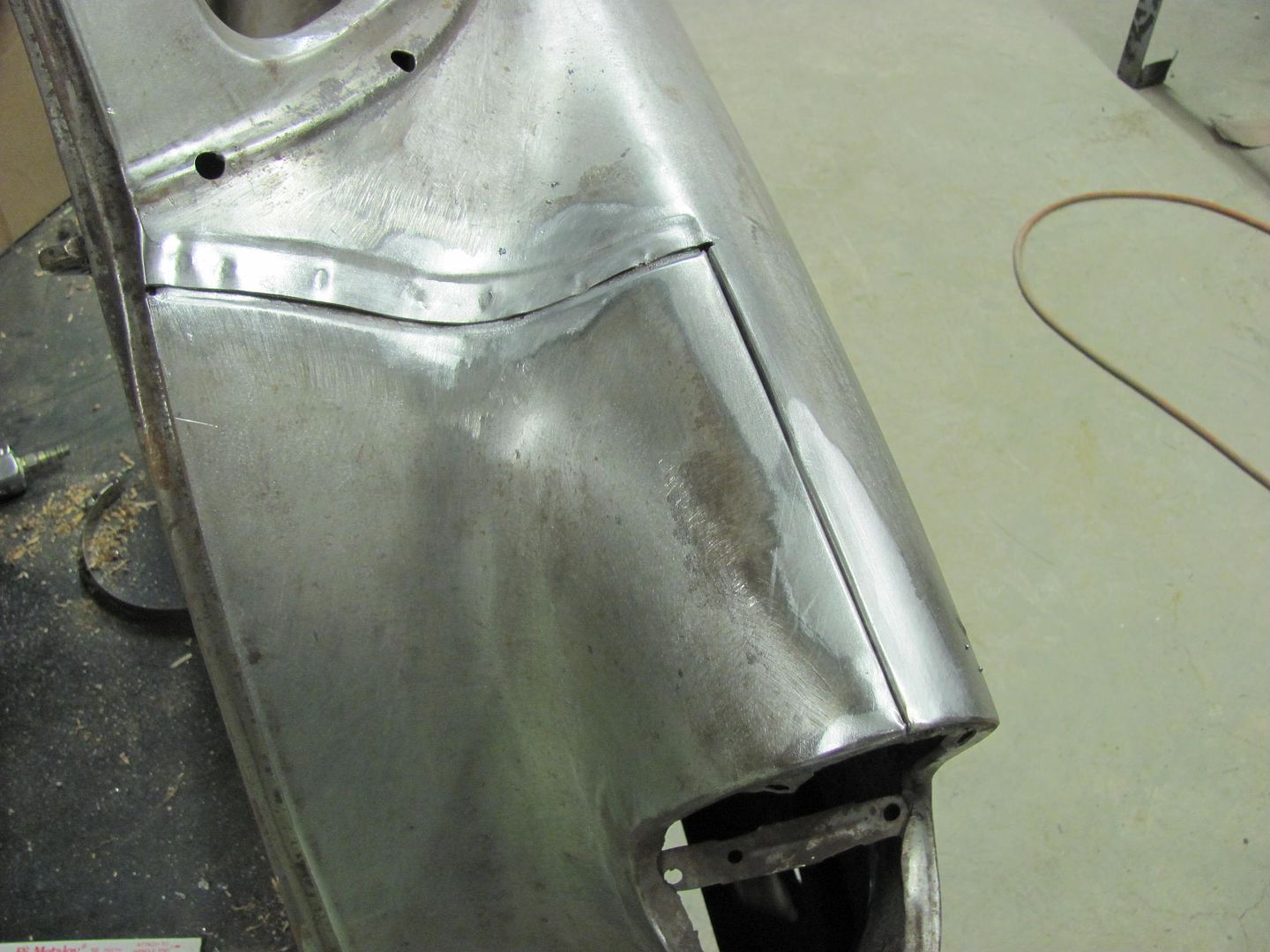
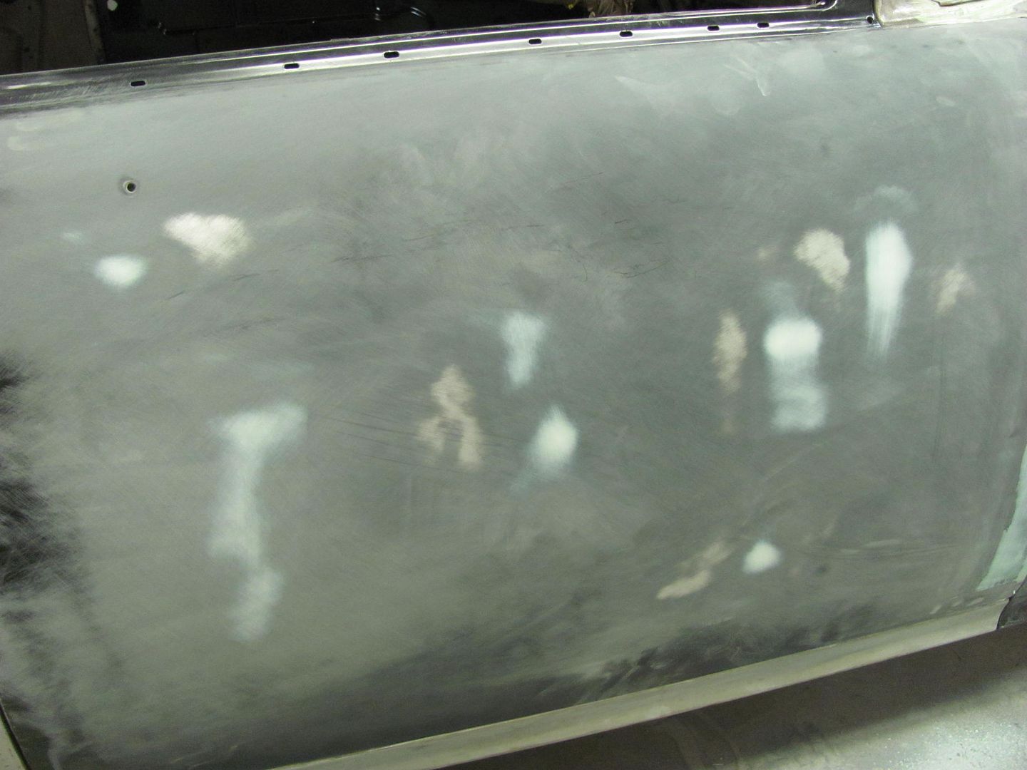
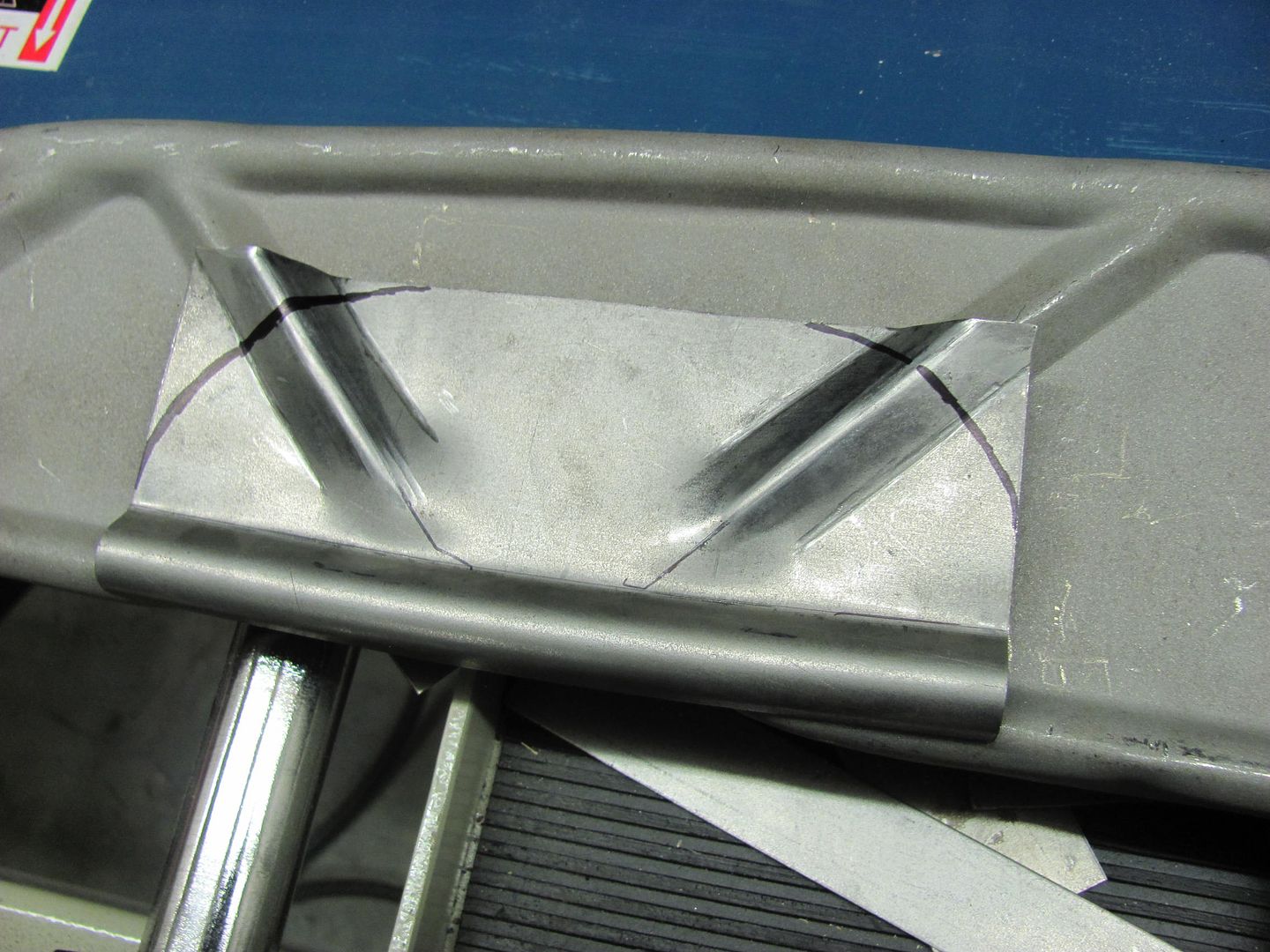
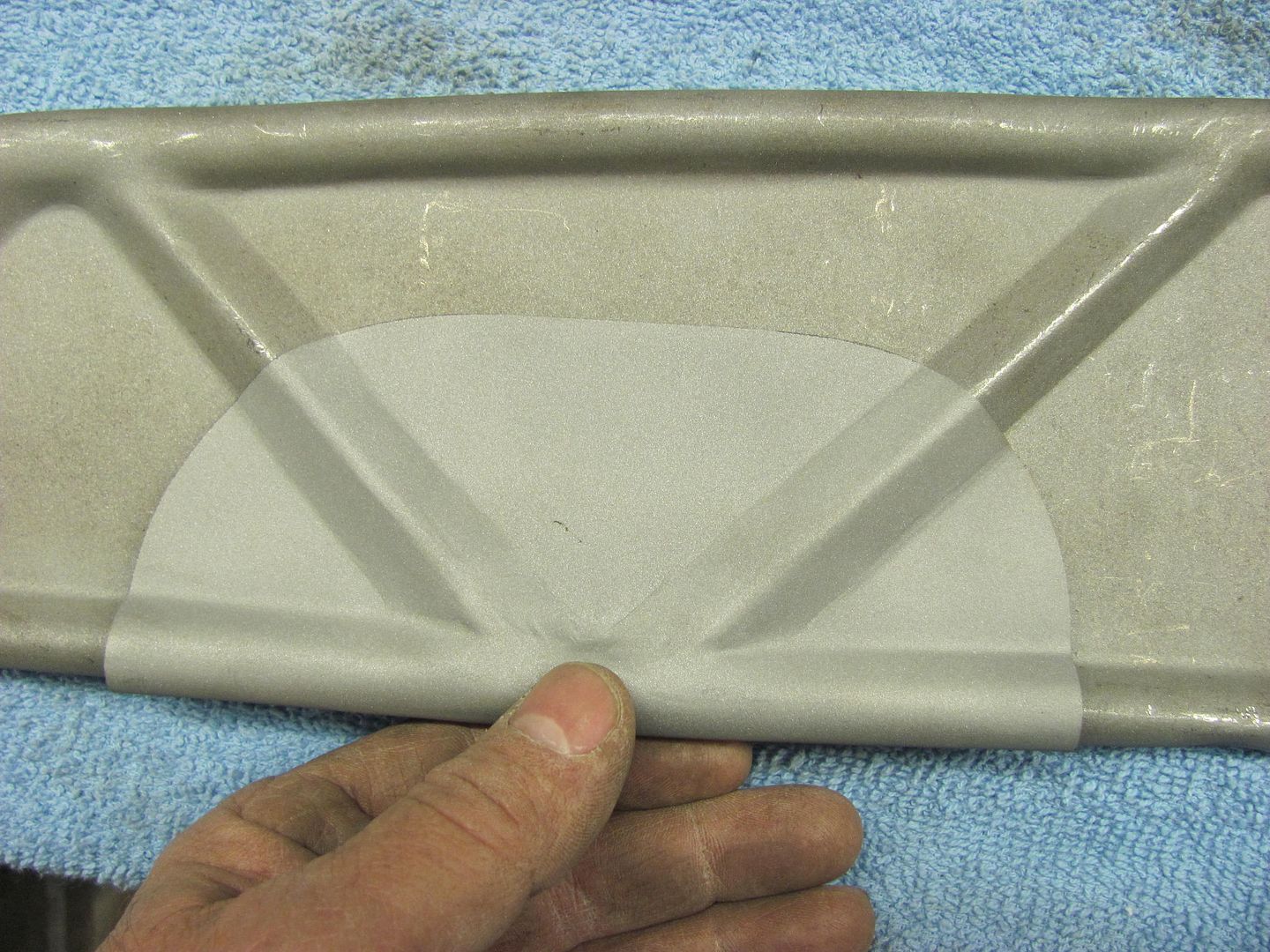
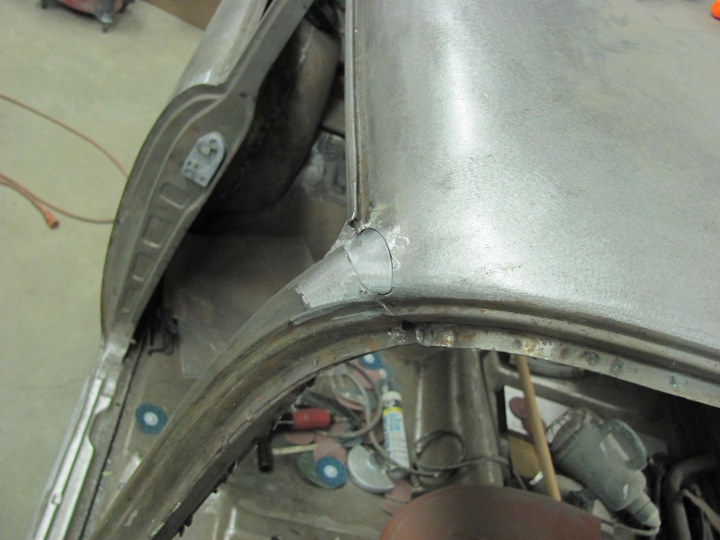
Roof skin patch trimmed and fitted...
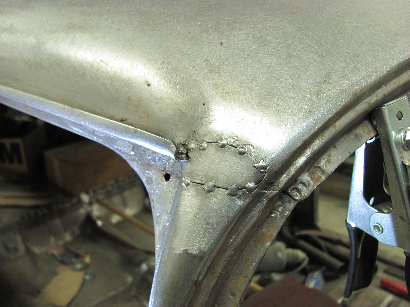


Picture1859.jpg


Picture1860.jpg


Welded...


Picture1862.jpg


Picture1864.jpg


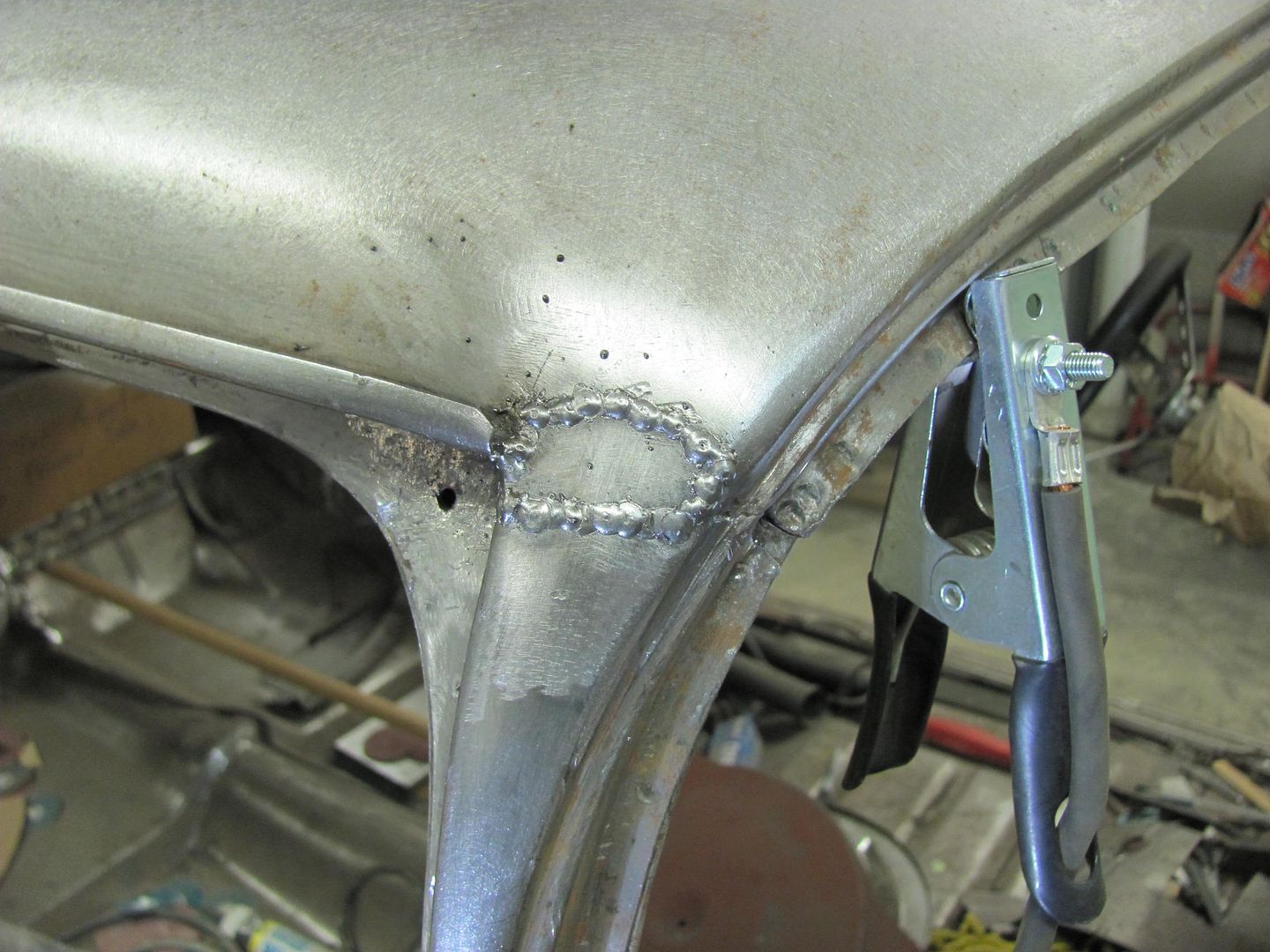
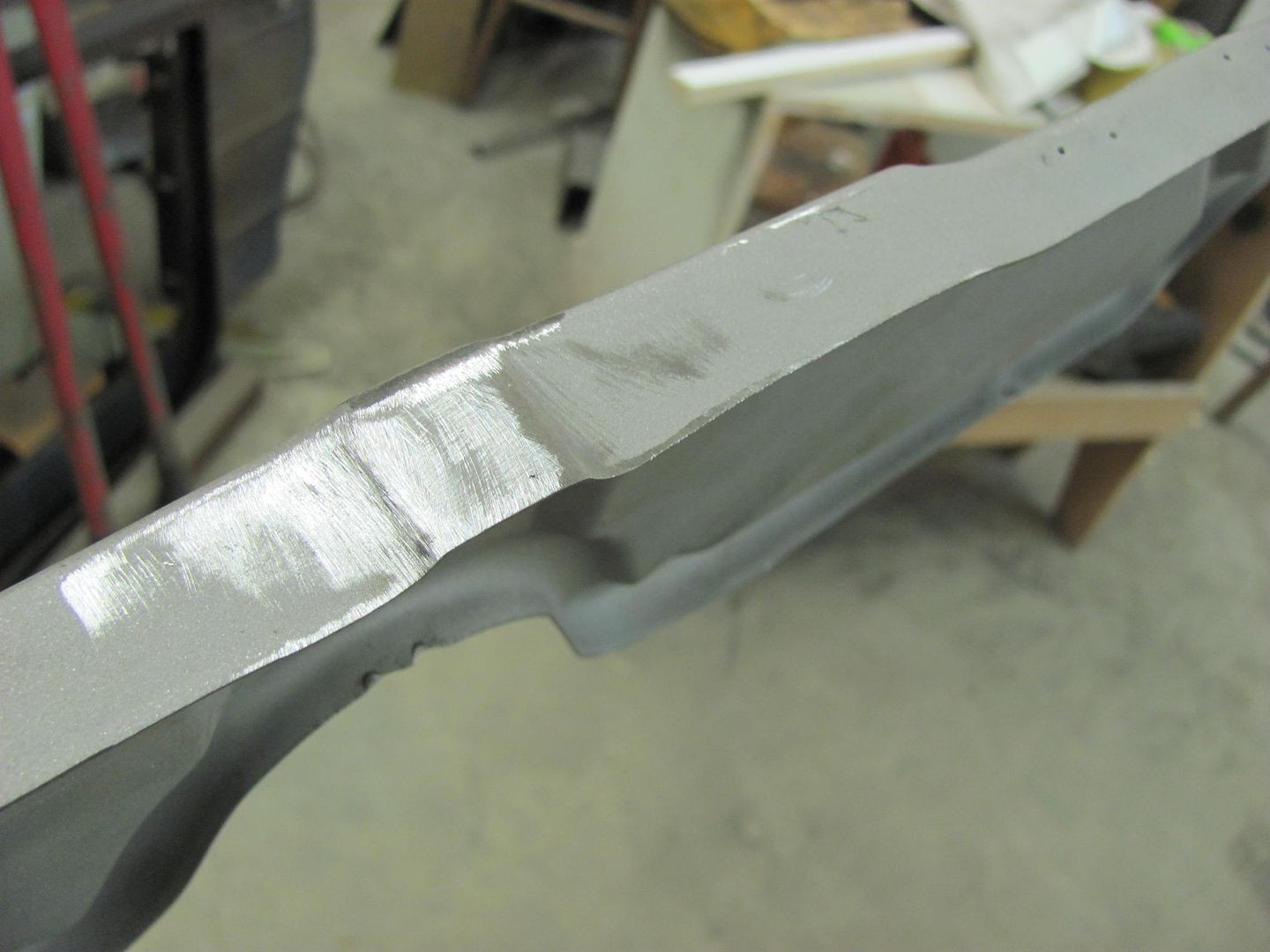
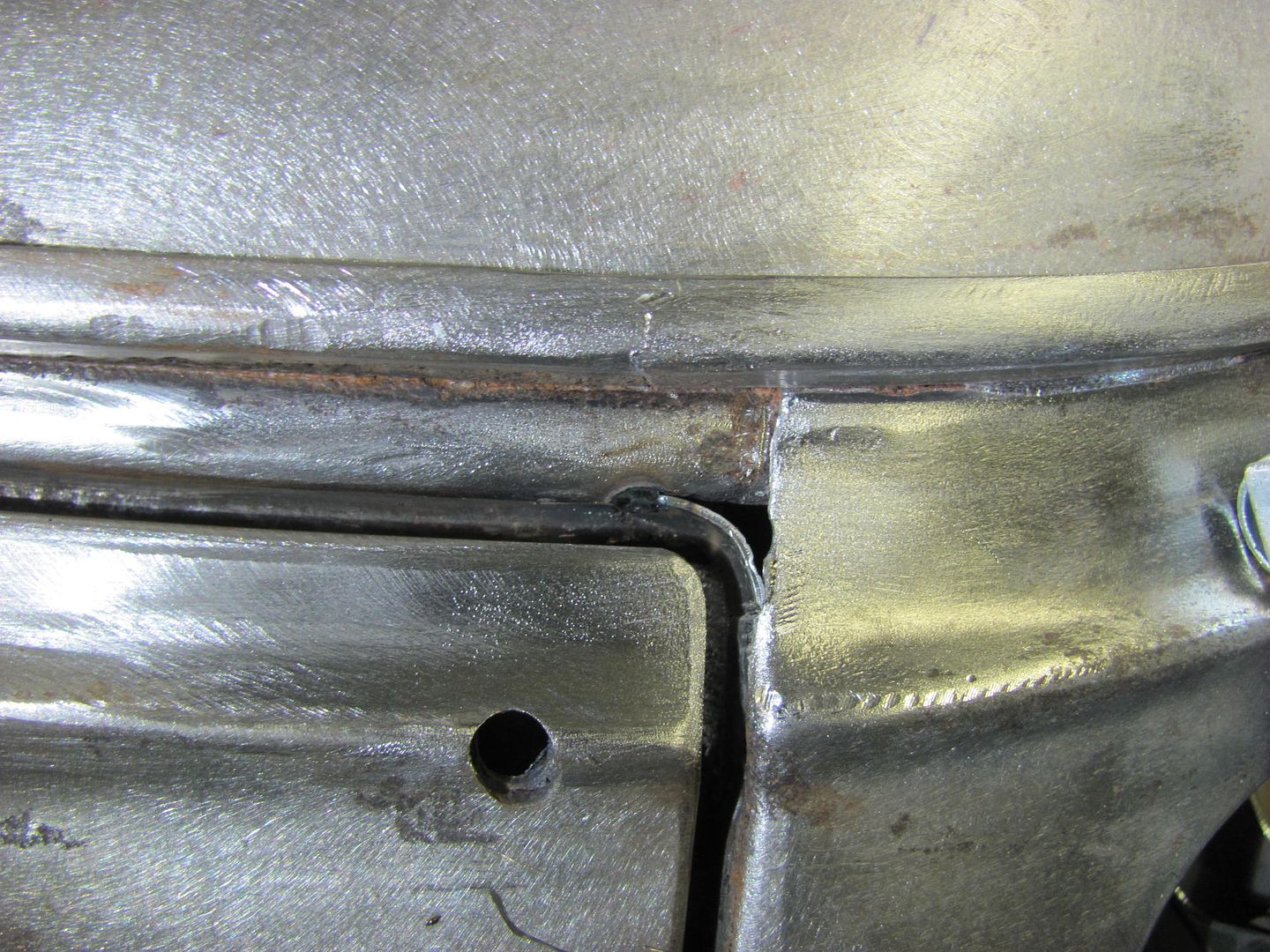
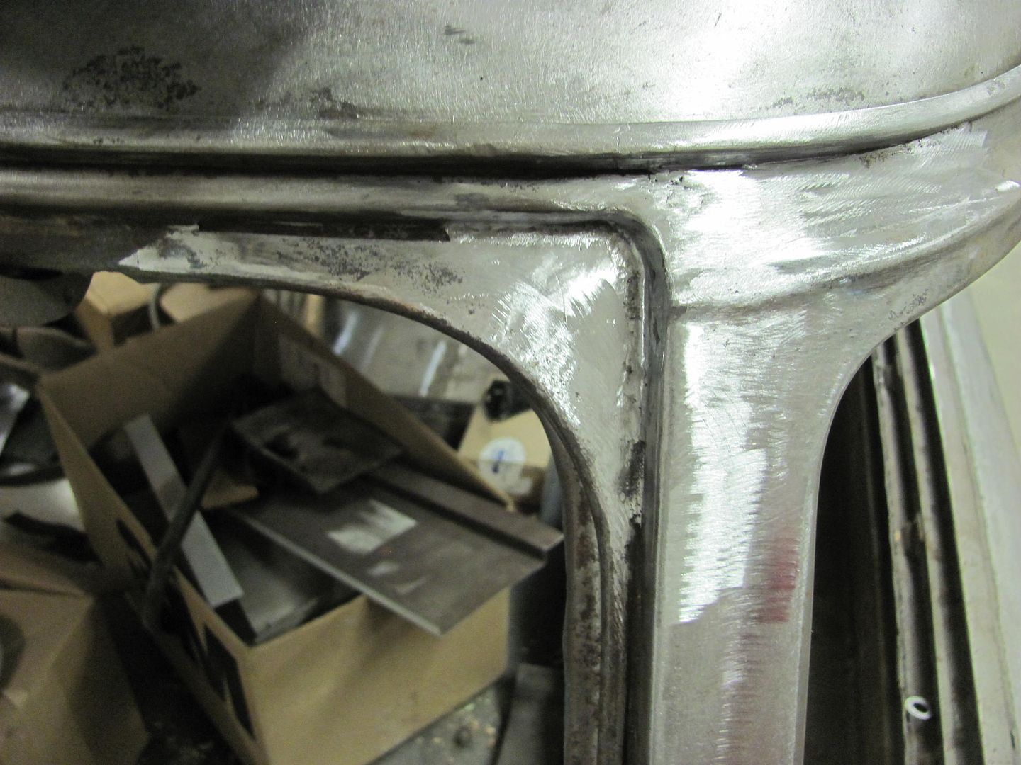
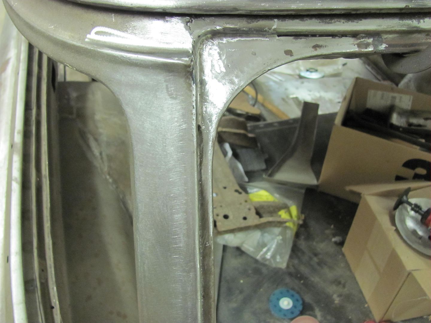
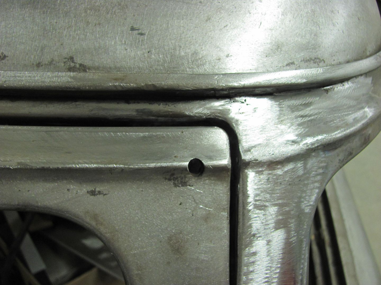
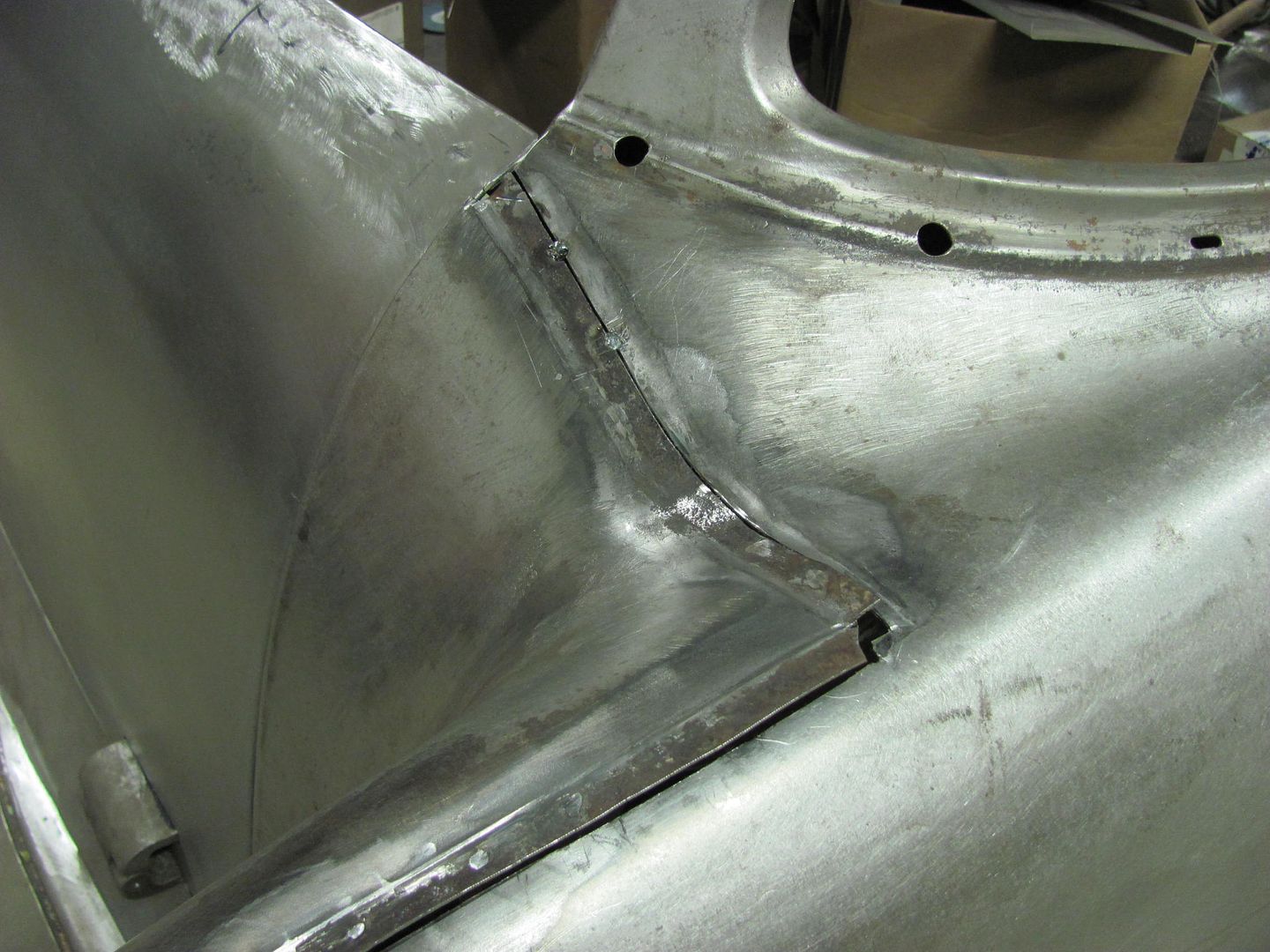
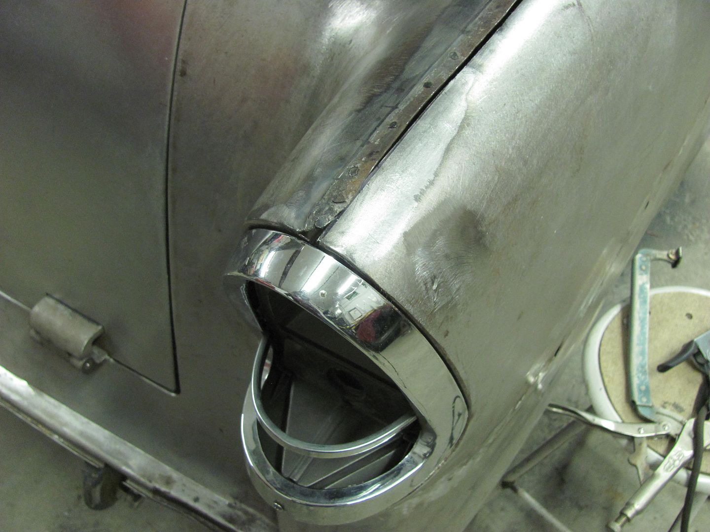
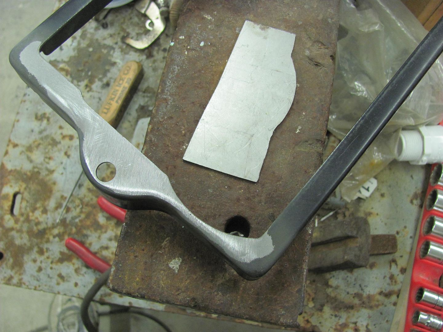
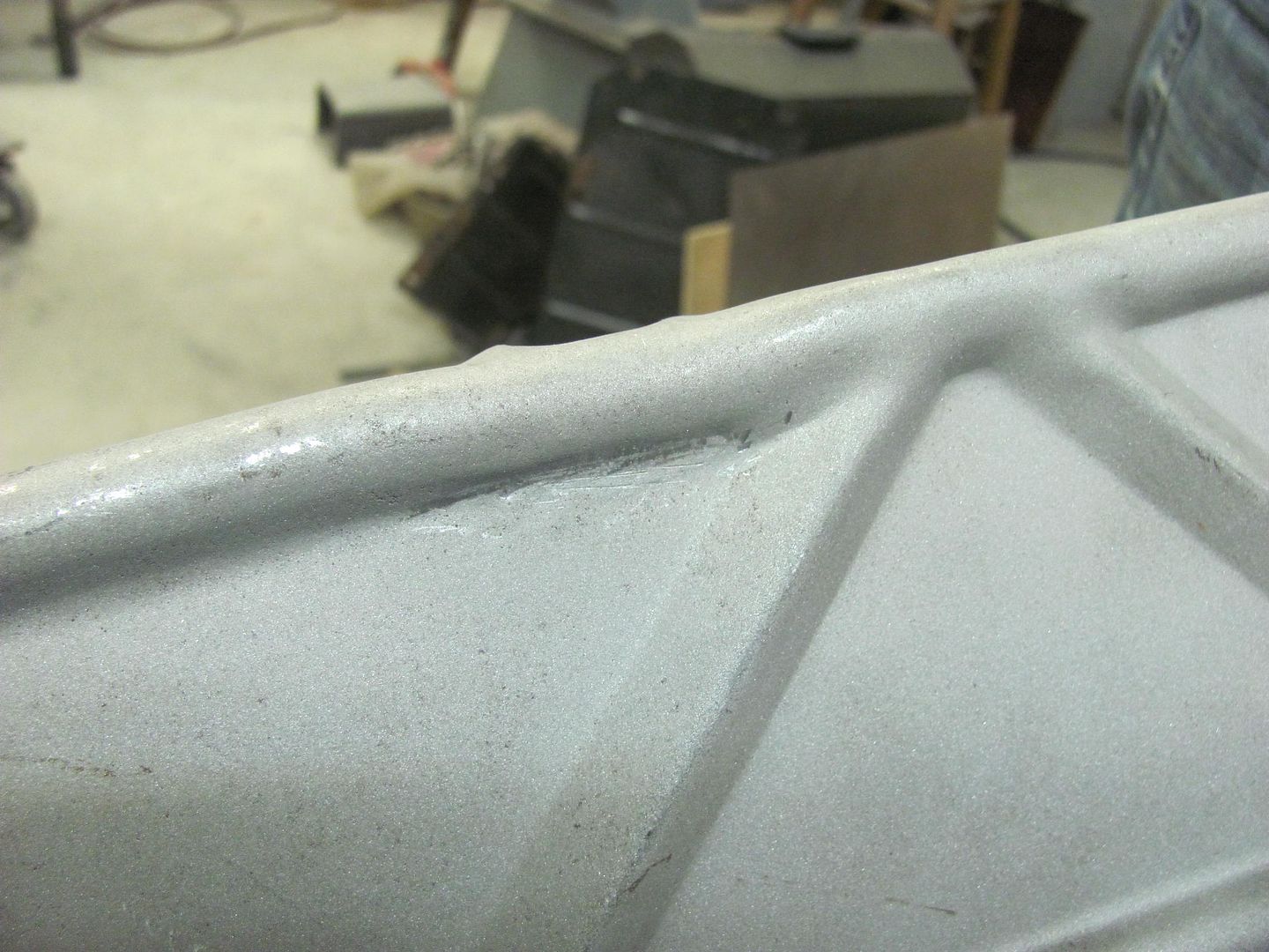
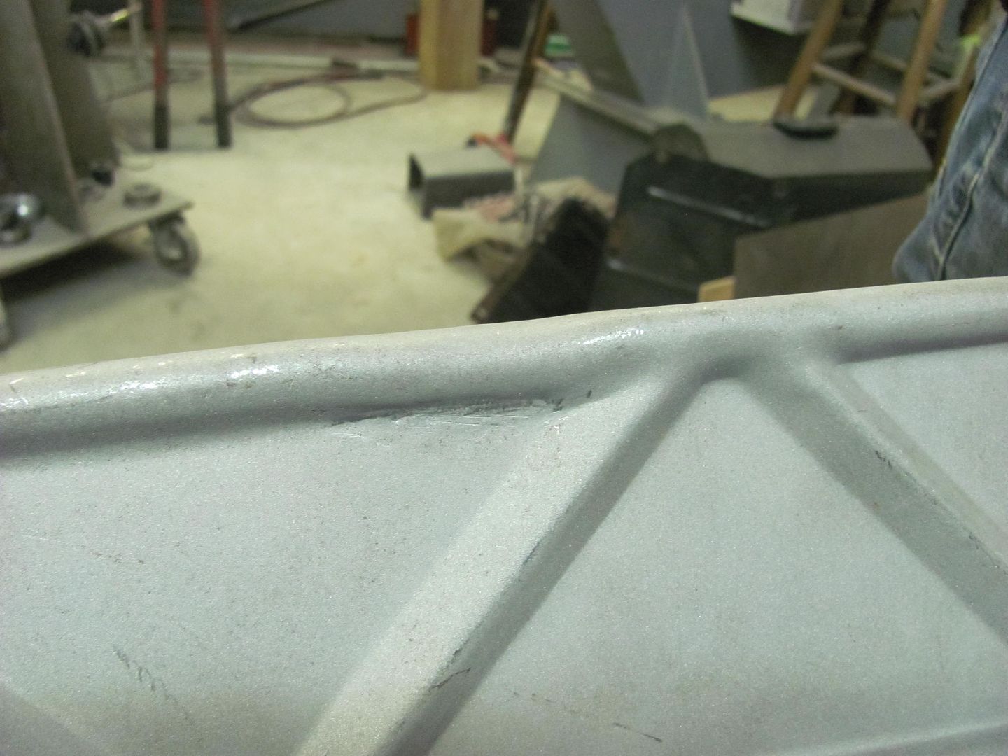
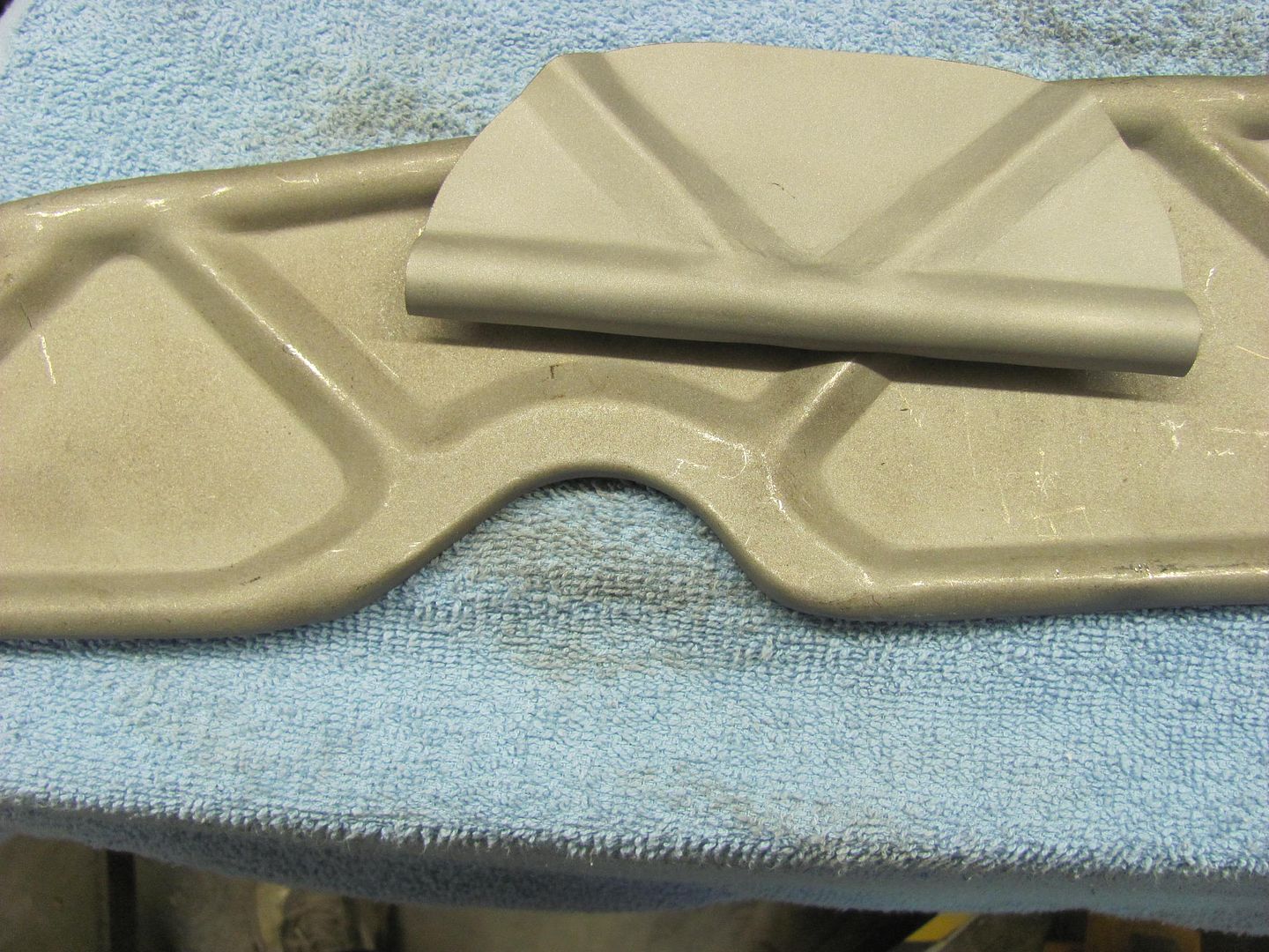
Welds dressed and radius checked...


Picture1865.jpg
 
More progress on the wagon today. Kyle had finished the media blasting on the hood brace, so we had a few areas to address. As the hood ornament no longer exists, we didn't need the mounting holes going through the brace.


Picture1868.jpg


A piece of brass flat bar is radius-ed to make an anvil..


Picture1869.jpg


High spot is heated and tapped down with the hammer.. Then pick the next high spot and repeat....


Picture1871.jpg


Picture1872.jpg


Picture1873.jpg


Slot is welded closed, welds dressed, area media blasted once again...


Picture1875.jpg


Picture1876.jpg


Picture1878.jpg


Kyle working on prepping the passenger door for primer... Sorry for the blurry picture, gonna have to fire the photographer!


Picture1874.jpg


The hood ornament hole in the cross brace was also welded closed and dressed...


Picture1880.jpg


Picture1881.jpg


Picture1882.jpg


Next on the list were the stress cracks on the ends of the hood brace.


Picture1883.jpg


Picture1884.jpg


Some 16 gauge CRS was used to make some stiffeners inside the corners...


Picture1885.jpg


test fit..


Picture1887.jpg


Plug welded in place and the flanges wrapped around... cracks repaired...


Picture1888.jpg


Picture1889.jpg


Picture1890.jpg


Picture1892.jpg


Test fit to the hood...


Picture1895.jpg
 
So true. People will walk in the shop and see the paint booth...."Oh, you do painting?" .....well, it's mostly rust repair :D
 
Tonight Kyle was putting the finishing touches on prepping the passenger door for paint. Lots of nooks and crannies. We ended up moving the drill press so we could open the media blast cabinet door wide enough to put the door inside. It was a snug fit, but made easier work of cleaning the door on the ends... The rest will be done by hand...


Picture1913.jpg


Picture1914.jpg


After adding the radius to the doors, it only made sense that the lift gate needed the same modification. Sorry to bore you with more of the same, just wait until we get to wet sanding :D


Picture1902.jpg


Picture1904.jpg


Test fit the radius...


Picture1905.jpg


Scoring the second cut location, and tacking in place..


Picture1906.jpg


Picture1907.jpg


Picture1908.jpg


Picture1909.jpg


Snapped of the excess....


Picture1910.jpg


Checking the radius, and welded in and dressed...


Picture1911.jpg


Picture1912.jpg


They're calling for a heat wave this weekend (in high 40's on Sunday), so we should get some more primer sprayed....
 
Kyle finishing up the prep on the door this morning, found another use for the GatorMeet radius square, here used as a sanding block to get into the tight crevices...


Picture1915.jpg


Front fenders were both prepped with DA and 80 grit..


Picture1917.jpg


Picture1918.jpg


SPI Epoxy is mixed to allow for induction...


Picture1920.jpg


Picture1919.jpg


As the body parts had been soda blasted, it was cleaned with a hot soapy water (dish detergent) and a grey Scotchbrite, followed by a towel drying session.


Picture1927.jpg


Then this was followed up with preclean...


Picture1921.jpg


Picture1922.jpg


Picture1924.jpg


The door handle backing plates had not yet been installed on the back side of the door skins, so a coat of epoxy was sprayed on both, and then bolted together to allow to cure..


Picture1928.jpg


Picture1930.jpg


A good shot of the door paint fixture in action...


Picture1936.jpg


Two coats applied...


Picture1937.jpg


Picture1938.jpg


Picture1939.jpg


Picture1940.jpg
 
Looks good, feels good getting the primer on after all that metal work I bet!
 
Looks great! Doesn't look like it will need a lot of blocking by those side shots of the fenders. What's the next step for these parts?
 
There are some dings that were missed and the gloss of the epoxy makes them easy to find. We'll work on some of those defects and get the parts bolted back on the car so they can be blocked across the gaps.. then lather, rinse, and repeat :D


This evening while we had painted parts still lounging in the booth, we took some time to clean up and put tools away..... hey, there's that welding table!


Picture1941.jpg


And found a new location for the ewheel.. Still gives plenty of room for access to the parts bins and gets it out of the way elsewhere in the shop..


Picture1942.jpg


After that we worked to fix some pin holes along the passenger quarter's weld.. using a light from the back side to show the pin holes...


Picture1945.jpg


Picture1943.jpg


....and this one was a pit from the back side, more of the dreaded dirt thrown from the rear tire causing rust....


Picture1944.jpg
 
Tonight we finished up radius-ing the liftgate opening...


Picture%201956.jpg


Picture%201955.jpg


Picture%201958.jpg


Picture%201957.jpg


Next, we moved on to de-leading and shaving the last pinch weld seam at the back of the car. We've eliminated all of these to get rid of all the dirt/rust traps that we can...


Picture%201959.jpg


Picture%201960.jpg


Picture%201961.jpg


Picture%201962.jpg


Removing the excess....


Picture%201963.jpg


Picture%201964.jpg


Picture%201966.jpg


Getting some gap filler.....


Picture%201967.jpg


Picture%201968.jpg


Picture%201969.jpg


Flattening out the creases....


Picture%201971.jpg


Picture%201973.jpg


Tacked in place, and test fitting a tail light before trimming our gap filler....


Picture%201979.jpg


Picture%201980.jpg


....and we'll get the rest of the de-leading finished on Saturday...
 
Sorry I'm a little late posting the progress from yesterday.. We were supposed to finish up the passenger rear quarter, but looks like some reproduction tail light bezels are on the way. So just to be on the safe side, we'll post pone that so any final fitment will be to those parts once they get here... In the meantime, we got the primed body parts re-assembled yesterday, here installing the doors.....


Picture%201981.jpg


Picture%201982.jpg


Picture%201983.jpg


Picture%201984.jpg


Picture%201985.jpg


The SPI epoxy does a good job of providing it's own "guide coat". I blocked this with 180 grit...


Picture%201988.jpg


Here's some of the low spots filled with some evercoat...


Picture%201992.jpg


While I was block sanding, Kyle started modifying the hold down bracket for the battery. The post cutouts were on catty corner and didn't match todays battery posts. We had test fit the bracket on a 24F series Interstate today at Big Ed's Tires. Here's the filler piece....


Picture%201990.jpg


Shown here is the new location...


Picture%201991.jpg


Filler welded in place, and the new relief cut out...


Picture%201986.jpg


Picture%201989.jpg


One down, one to go...
 
Awesome photo documentation and work :)

I used to "deburr" with the drill bit method. One day while doing some stainless tubing in a mechanical room I looked at the deburring tool I was using and thought, cut off a half inch of the plastic and presto a great sheet metal hole deburring tool.

7478202-23.jpg
 
SOF, that looks like a tool I'll need to pick up, thanks for the info!


Tonight's update. We took delivery on some nice used core support side panels from Jay Hammond's Chevy Parts. The others were quite mangled, so this will save quite a bit of time in making a set.


Picture%201994.jpg


Kyle finishing up the battery hold down modification...


Picture%201993.jpg


Picture%201995.jpg


Picture%201996.jpg


We also mocked up an MT24F battery...


Picture%201998.jpg


The factory version of this battery location for an air conditioned car also calls for a "zee" bracket to the back side of the core support.


Picture%202002.jpg


Picture%201999.jpg


So with dimensions taken, a practice piece was cut out of poster board...


Picture%202000.jpg


Picture%202001.jpg


Laid out on some 16 GA CRS...


Picture%202004.jpg


And got a bit more blocking done across the door gaps..


Picture%202003.jpg


Picture%202006.jpg
 
Today Kyle cut out the battery tray's zee bracket, and I had told him we should tip the top lip first and then make the vertical bends...


Picture%202007.jpg


Picture%202008.jpg


Picture%202010.jpg


As you can see, it turned out horribly, and sometimes I need a learning curve myself... :)

We had used a narrow bottom die to tip the top flange, and should have also used something different for the vertical bends.


Picture%202015.jpg


So let's back up and punt, here bending the vertical bends FIRST and using a roll former die to keep any markings to a minimum. We did a partial bend here, then did a partial tip, and jumped back and forth a few times for a much better result:


Picture%202018.jpg


Picture%202019.jpg


Picture%202020.jpg


Plug welded through the thinner battery hold down into the 16 ga metal of the zee bracket using a Letter A sized holes and enough heat for weld penetration to show on the back side...


Picture%202021.jpg


Picture%202022.jpg


Picture%202023.jpg


Picture%202024.jpg


Also did more fine tuning on the front end today..


Picture%202011.jpg


Picture%202025.jpg


Picture%202026.jpg


Test fit of the "early" side emblem..


Picture%202012.jpg


Picture%202013.jpg
 
I like it! It sands much easier than the H/K, and is considerably less expensive.. Also like not having to use guide coat..
 
We noticed the driver's side hood gap was a bit tight and then noticed a difference in the end plates on the core support. The driver's side appears bent straight, so some hammer action made them more consistent and helped out the gap issue..


Picture%202038.jpg


Picture%202039.jpg


Picture%202040.jpg


After checking the hood brace to core support for any fitment issues, we noticed some cutouts that will allow the air around the radiator. This opening, although minimal, was re-formed with a couple of fancy chisels..


Picture%202027.jpg


Picture%202028.jpg


Picture%202029.jpg


Picture%202030.jpg


Picture%202031.jpg


The excess metal ruffles were addressed easily with the kick shrinker...


Picture%202032.jpg


Picture%202033.jpg


The next opening was a bit more substantial, and would require some replacement metal. Here was our first attempt at a bead along the edge of the panel..


Picture%202036.jpg


The dies would not permit quite enough length, so we used a vee die off the press brake and a 1/2" steel rod to make a radius die for the mag brake..


Picture%202041.jpg


Picture%202042.jpg


...and between that and a straight die in the press brake, the edge bead was formed...


Picture%202045.jpg


...here transposing the crease locations...


Picture%202043.jpg


Picture%202044.jpg


To pre-stretch the areas for the diagonal vee beads, we loaded these in the bead roller....


Picture%202046.jpg


Picture%202047.jpg


This didn't appear to add enough stretch, so the linear stretch die was used in the Watervliet planishing hammer....


Picture%202048.jpg


Picture%202049.jpg


Vee was added using 3/4 wide female bead die and a narrow tipping die..


Picture%202050.jpg


A bit of heat was added to make it a bit easier to transition the round and vee beads together...


Picture%202053.jpg


Picture%202054.jpg


Picture%202055.jpg


Picture%202056.jpg


....and this one we'll get formed up on Wednesday night and get both welded in place...


Picture%202057.jpg
 
I had a bit of a short night as I had to pick up the young'n from after school activities, so most of the progress this evening was Kyle's efforts.


Making the patch for the center relief, starting with adding the radius to the bottom edge... This uses a bottom vee die from the Diacro and a 1/2" rod to form the radius..


Picture%202058.jpg


Picture%202059.jpg


Test fit of the radius...


Picture%202060.jpg


Trimming out the hood brace...


Picture%202061.jpg


Scribing the patch....


Picture%202064.jpg


Trimming some of the excess on the bandsaw, and then fine tuning with the snips....


Picture%202066.jpg


Picture%202067.jpg


Picture%202068.jpg


I did work a bit more on hood gaps.. an official gap gauge shown here....


Picture%202073.jpg


Picture%202075.jpg


Also took some radiator leak preventative measures....


Picture%202069.jpg


Picture%202070.jpg


Trimming the other patch for the hood brace....


Picture%202072.jpg


Kyle persuading the patch's crease over a bit. This uses a glancing blow to keep the crease's new location from sliding down on the anvil...


Picture%202071.jpg


Both pieces clamped in place, we'll get some welding done on Saturday...


Picture%202076.jpg
 
Back
Top