You are using an out of date browser. It may not display this or other websites correctly.
You should upgrade or use an alternative browser.
You should upgrade or use an alternative browser.
Wagon Progress
- Thread starter MP&C
- Start date
MP&C
Member
Thanks for the kind words...
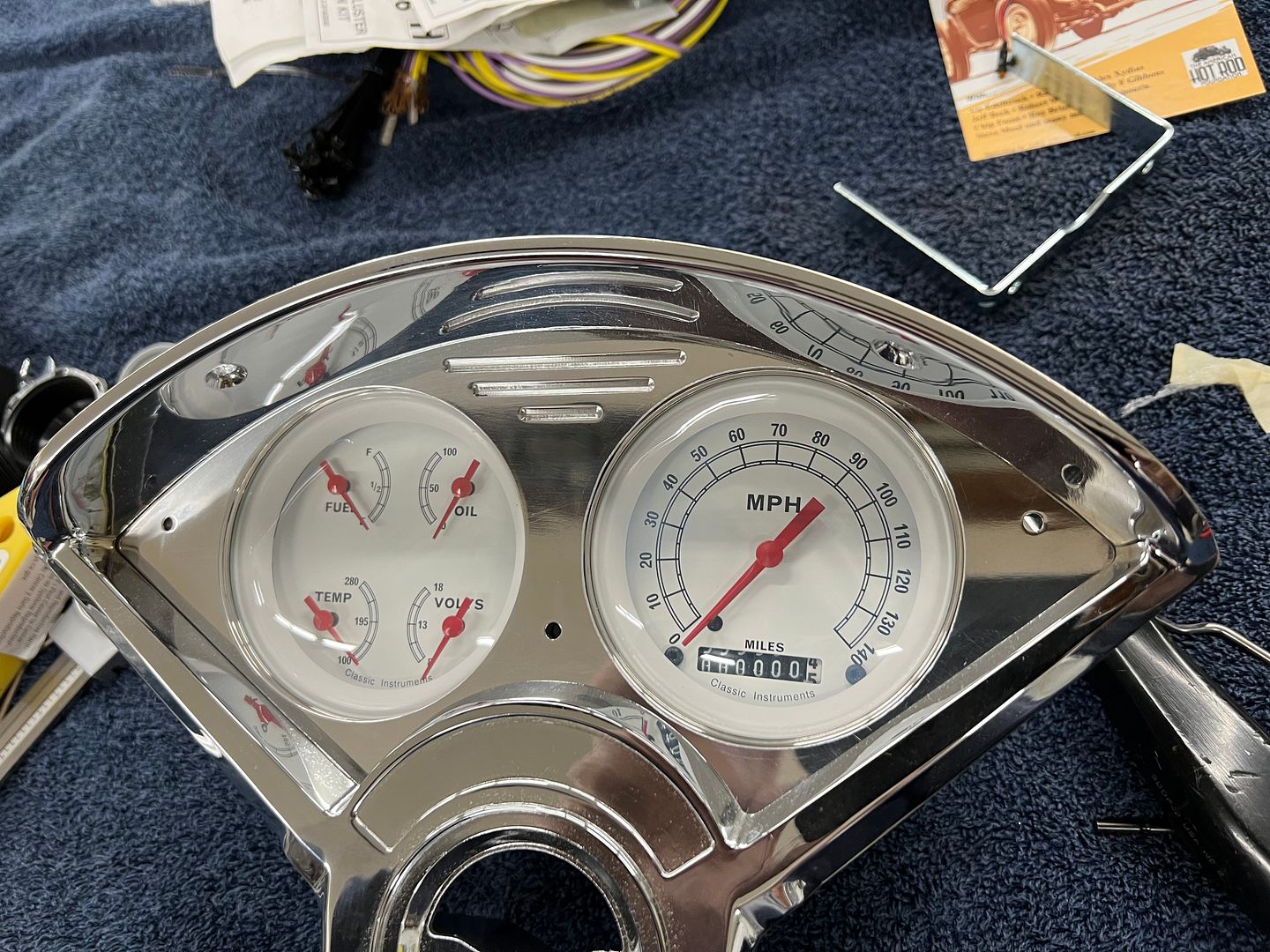
While we're getting prepared for wiring installation, the instrument cluster was dug out of its box to help us see where all the wiring was going. And there it was in all it's billet glory. This will kinda clash with the ribbed stainless trim we're using for the dash insert, so let's look at adding it to our gauge cluster as well...
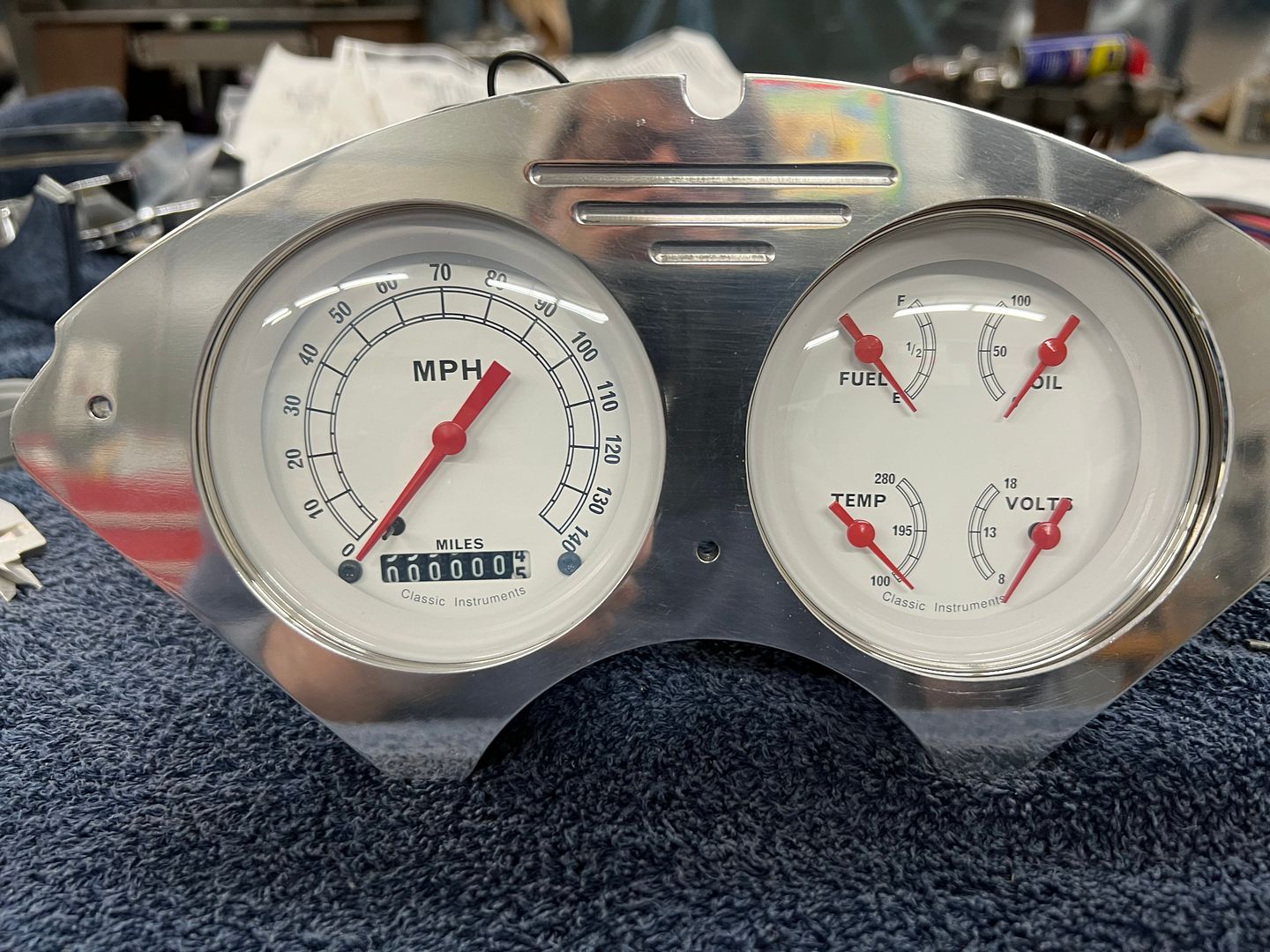
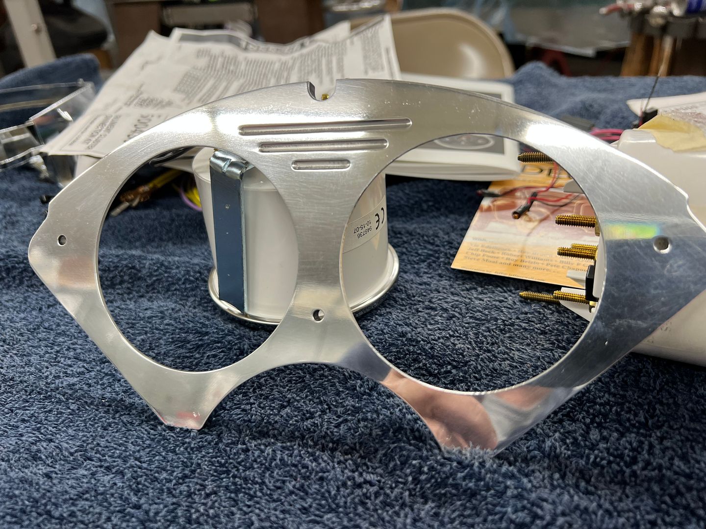
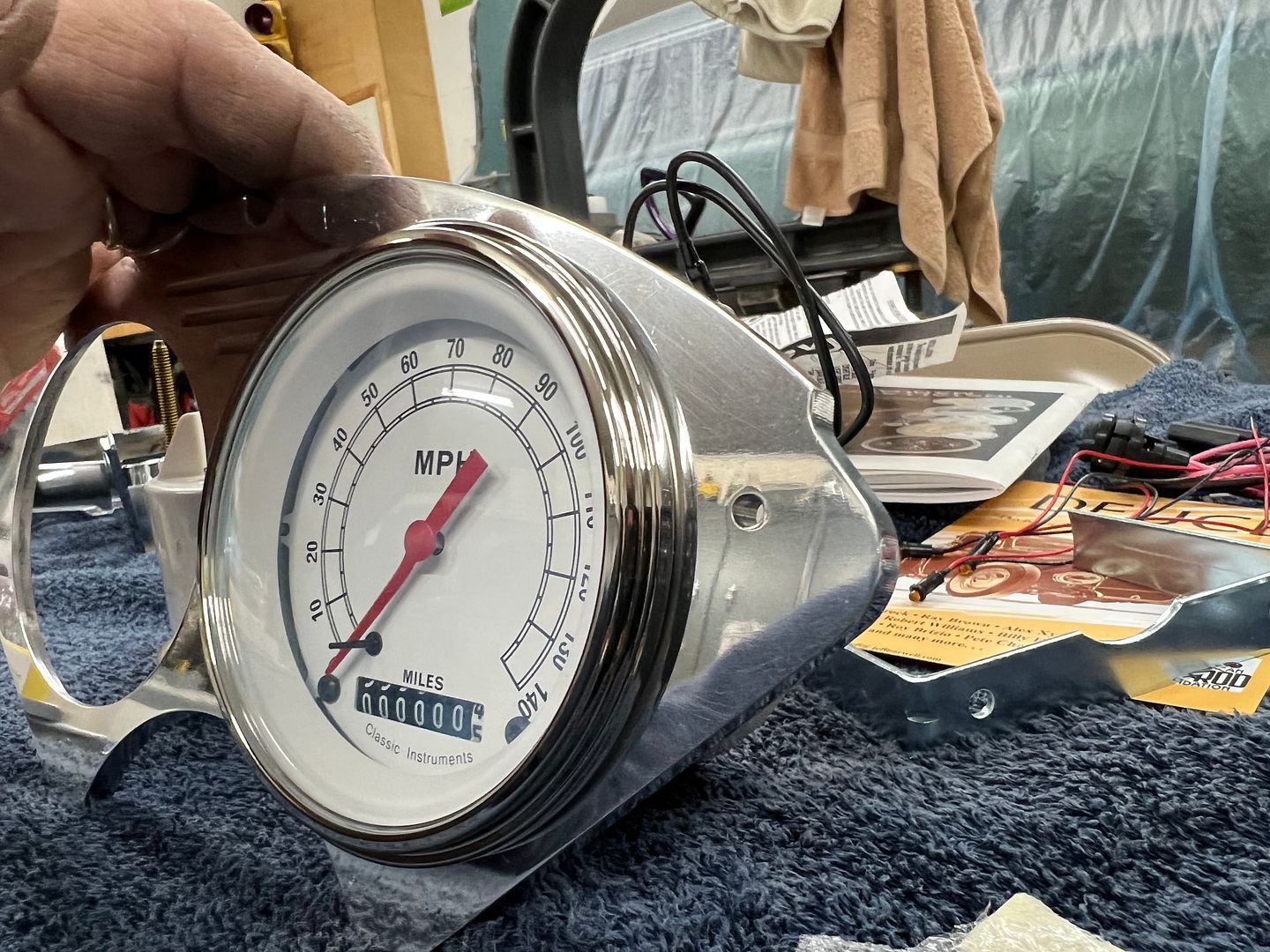
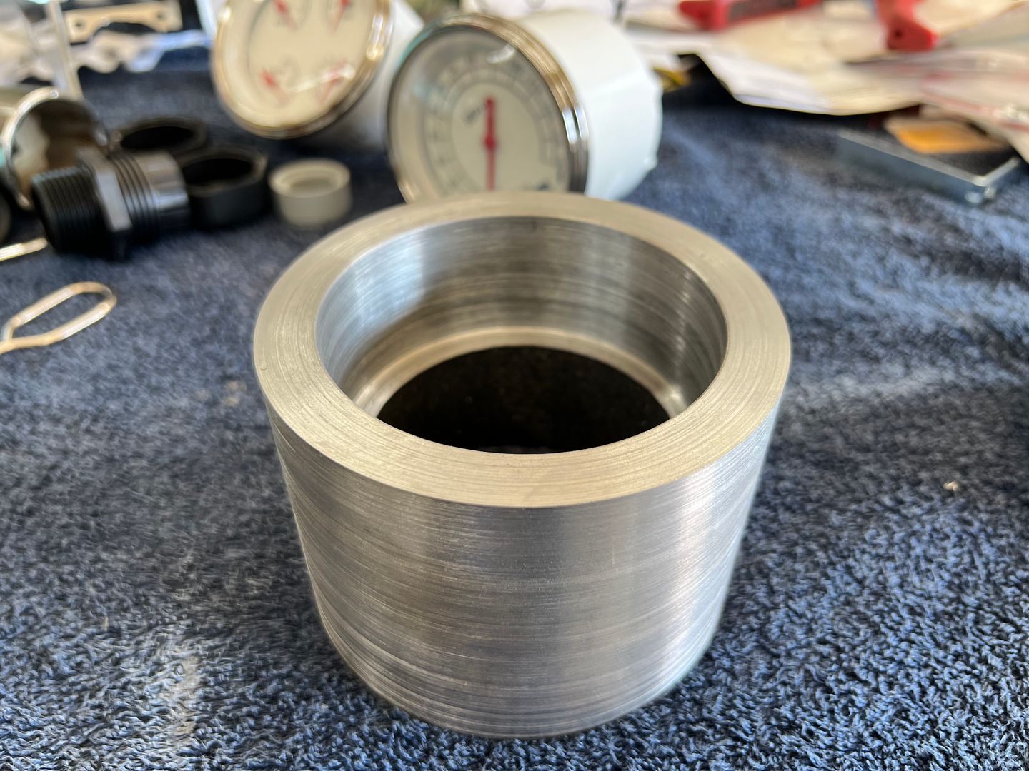
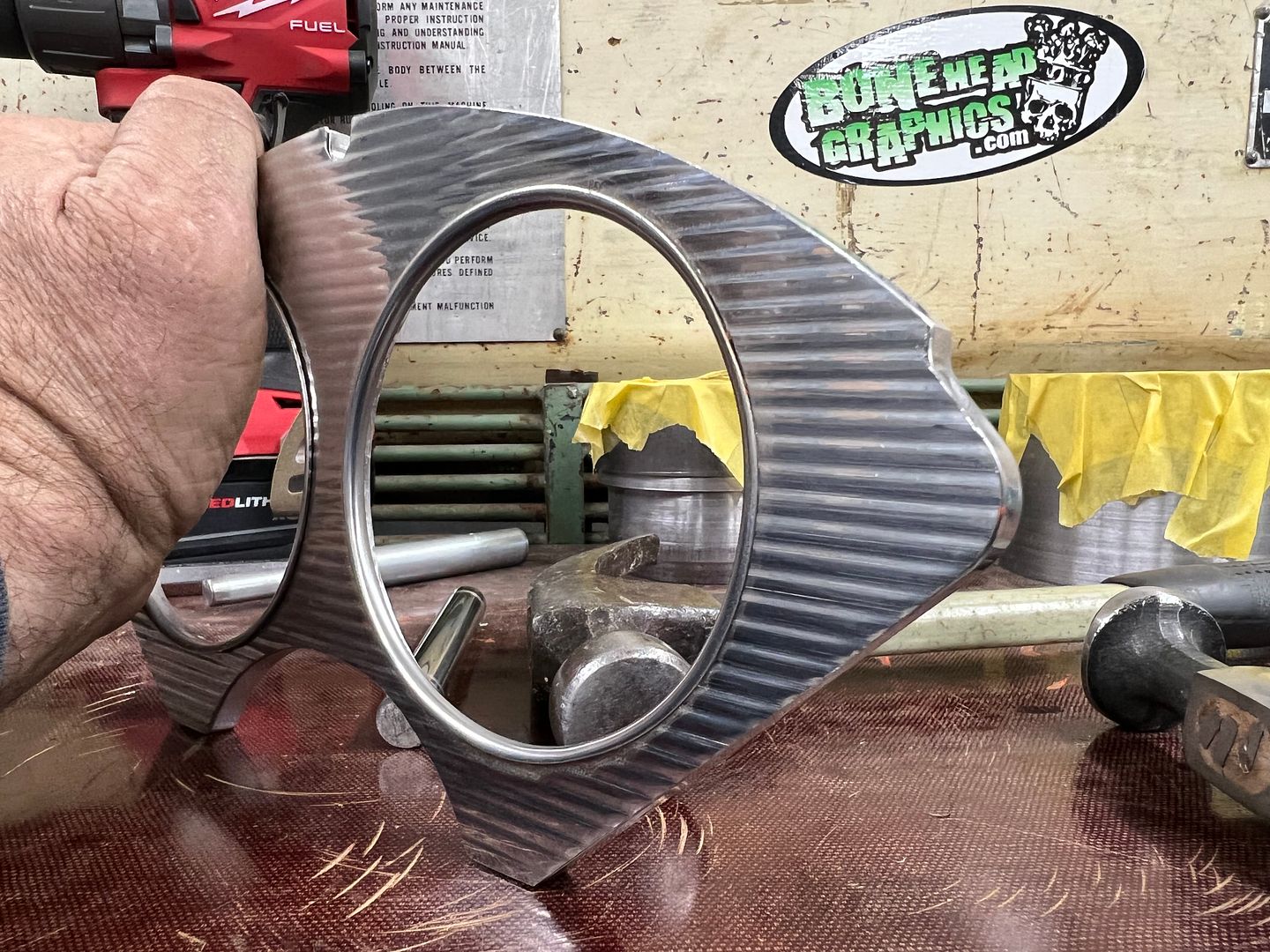
Where this gauge cluster was designed with a flush fit in mind, we need to be able to hide the cut edge of the ribbed stainless. So the holes were opened up slightly where the gauge could be installed from the front, and the bezel will now hide our cut edges..
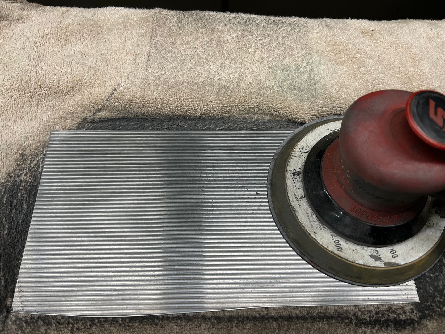
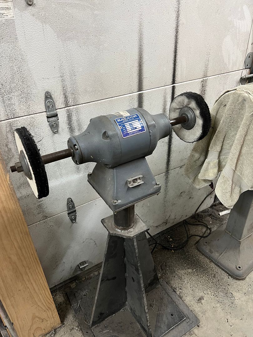
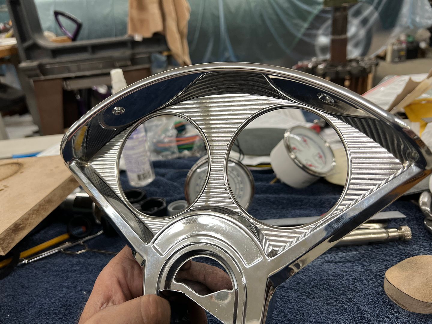
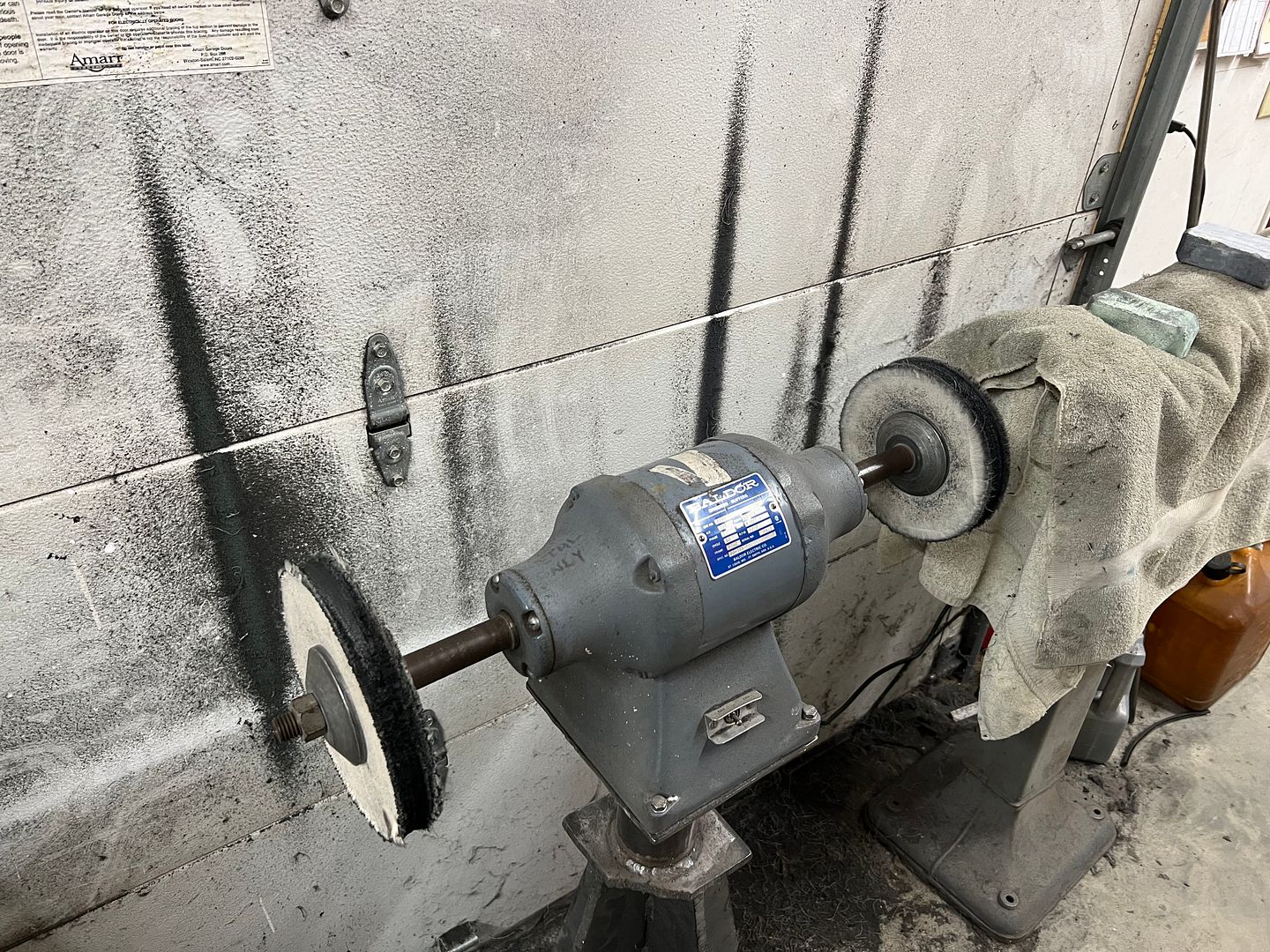
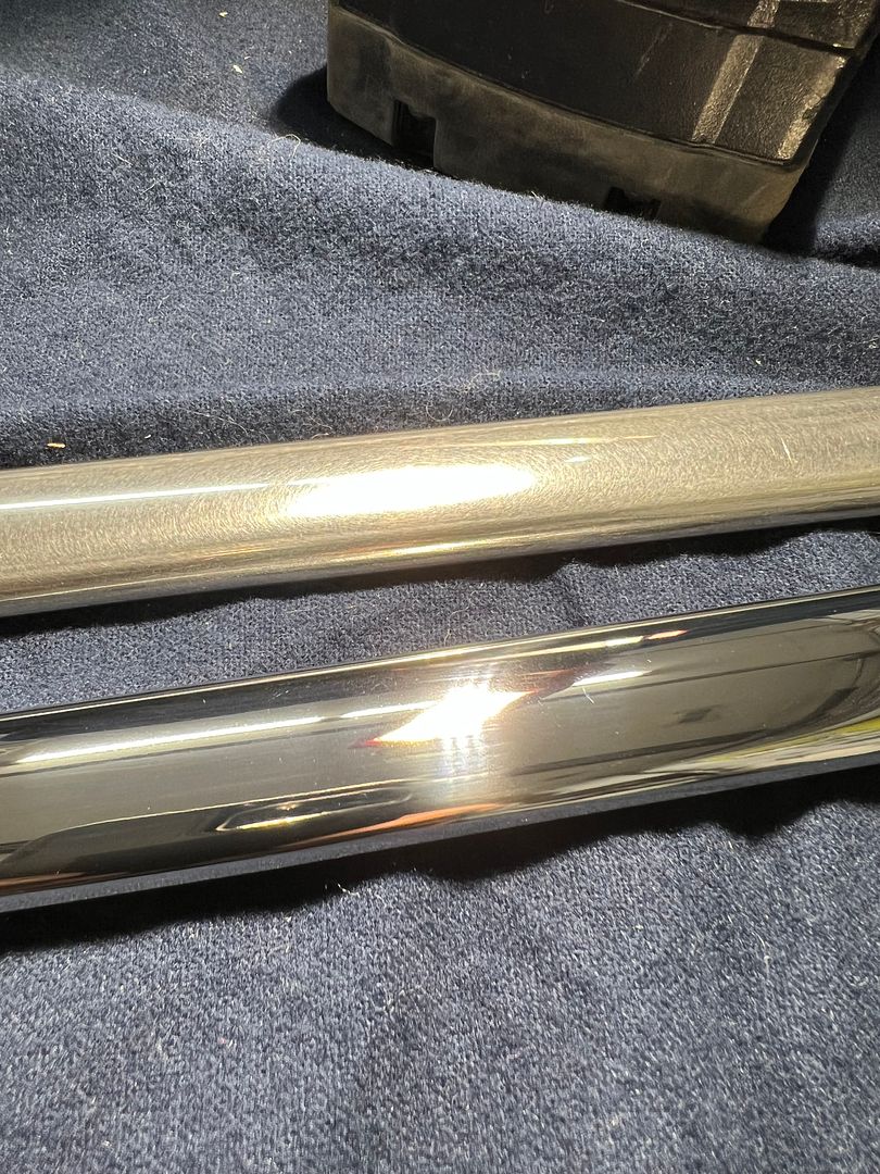
The stainless is in a rather raw form, and to give it more pizazz, perhaps some polishing is in order... So we used some Trizact products on the DA, and ended things on the buffer...
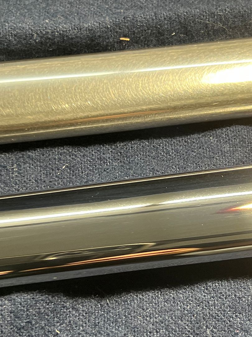
Here's how it turned out...
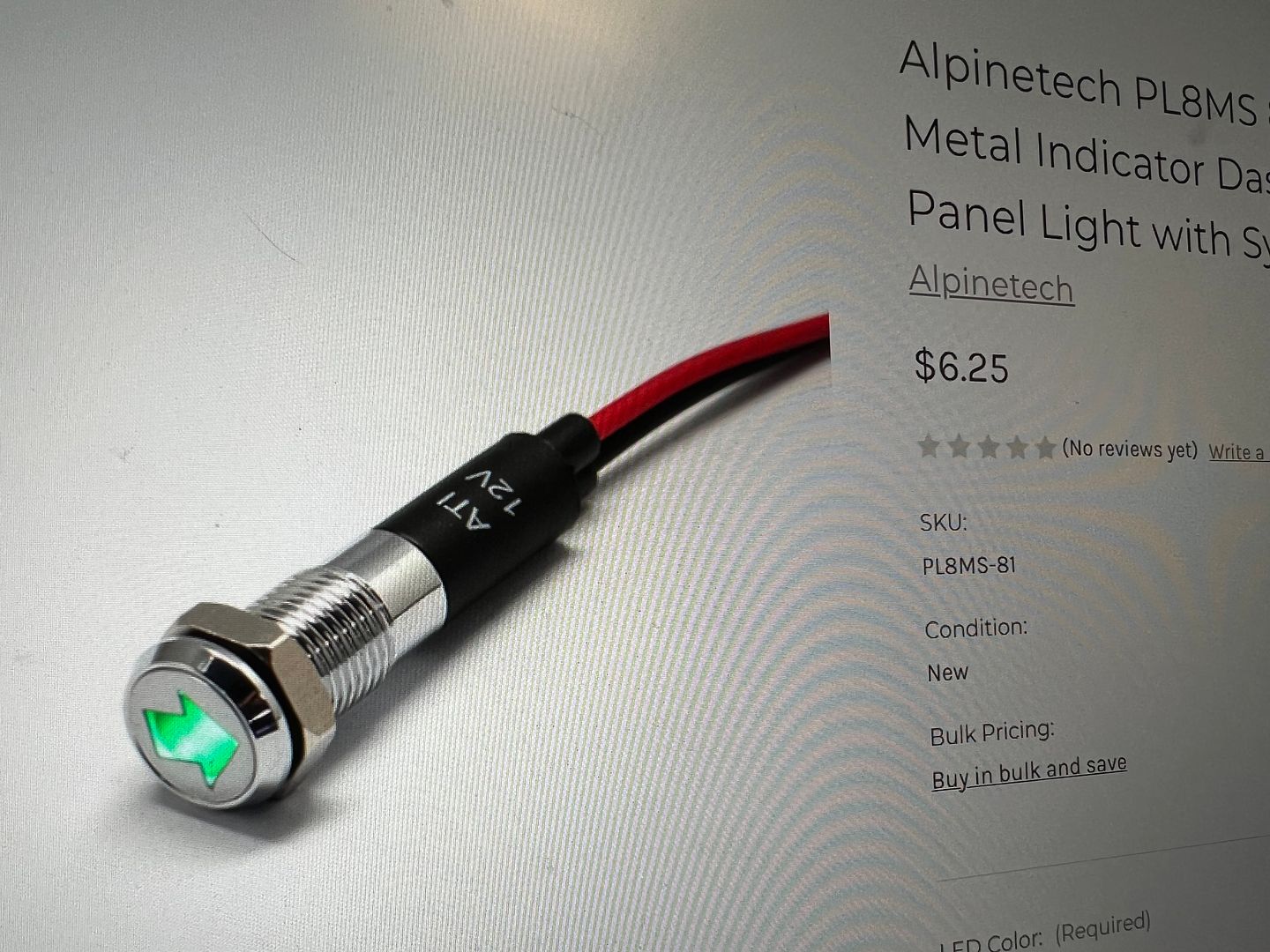
We also have some new indicator lights coming for the high beam and turn signals to get away from the tiny LED's that also scream billet.. The new lights should hopefully be here Saturday where we can get this modification wrapped up this weekend..
While we're getting prepared for wiring installation, the instrument cluster was dug out of its box to help us see where all the wiring was going. And there it was in all it's billet glory. This will kinda clash with the ribbed stainless trim we're using for the dash insert, so let's look at adding it to our gauge cluster as well...
Where this gauge cluster was designed with a flush fit in mind, we need to be able to hide the cut edge of the ribbed stainless. So the holes were opened up slightly where the gauge could be installed from the front, and the bezel will now hide our cut edges..
The stainless is in a rather raw form, and to give it more pizazz, perhaps some polishing is in order... So we used some Trizact products on the DA, and ended things on the buffer...
Here's how it turned out...
We also have some new indicator lights coming for the high beam and turn signals to get away from the tiny LED's that also scream billet.. The new lights should hopefully be here Saturday where we can get this modification wrapped up this weekend..
MP&C
Member
Today we had a back up and punt moment. The nice chrome bezel on the gauges is far too large to fit in those corners of the instrument panel bezel from the outside. So we'll have to keep it on the backside, but that doesn't help us cover up the cut edge of the hole in the ribbed stainless..
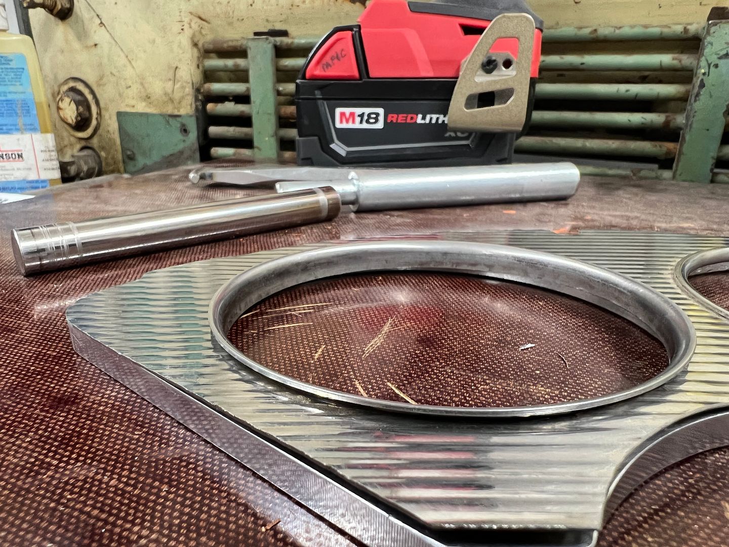
......so let's make some stainless "eyelets" to both hold the ribbed stainless securely to the billet panel, as well as give us a finished edge around the cut hole.. First a punch and die will be needed to press one side of our eyelet.
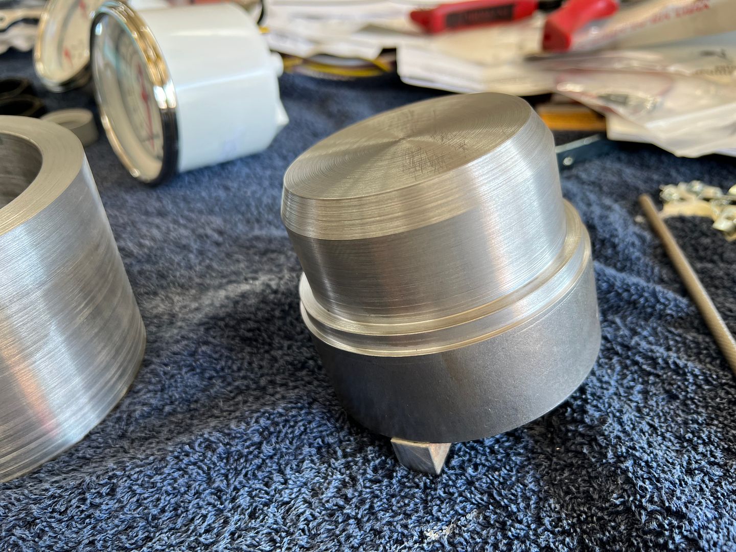
and we added a 1/2 x 1/2 tang to hold the punch in the press brake...
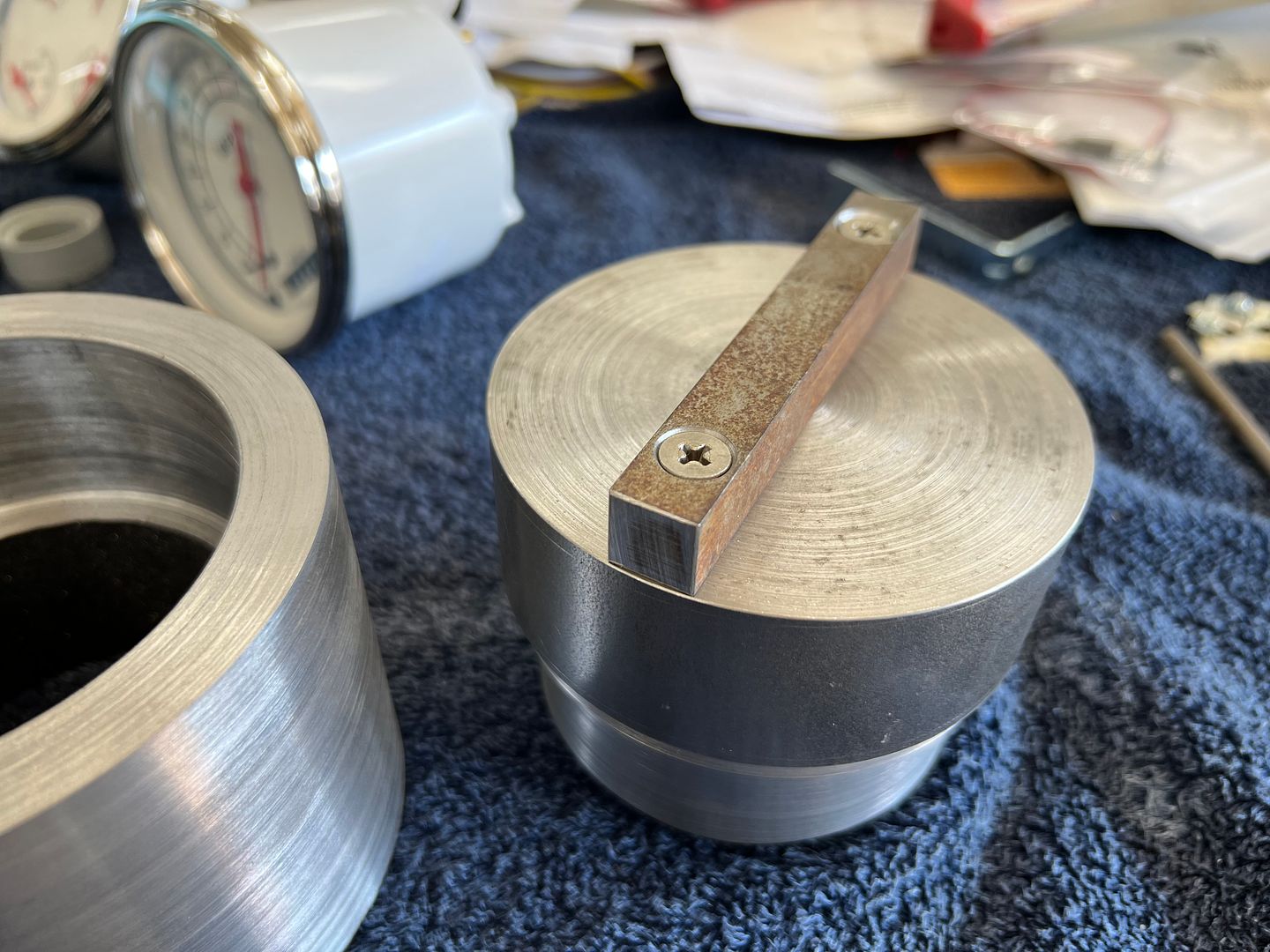
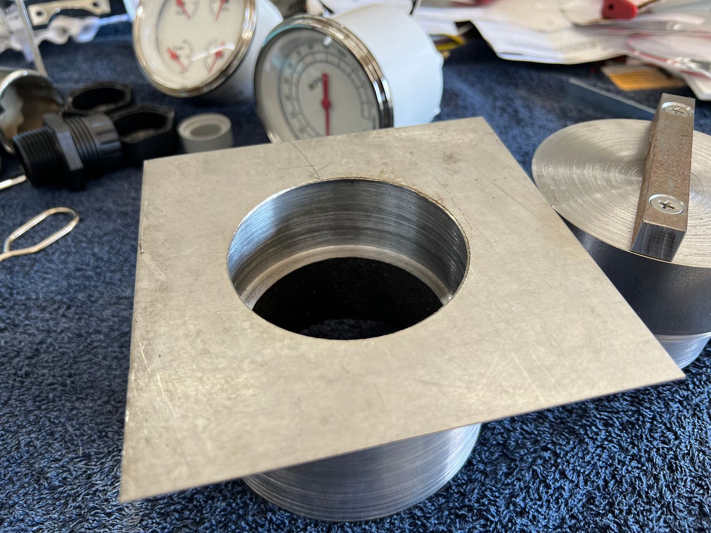
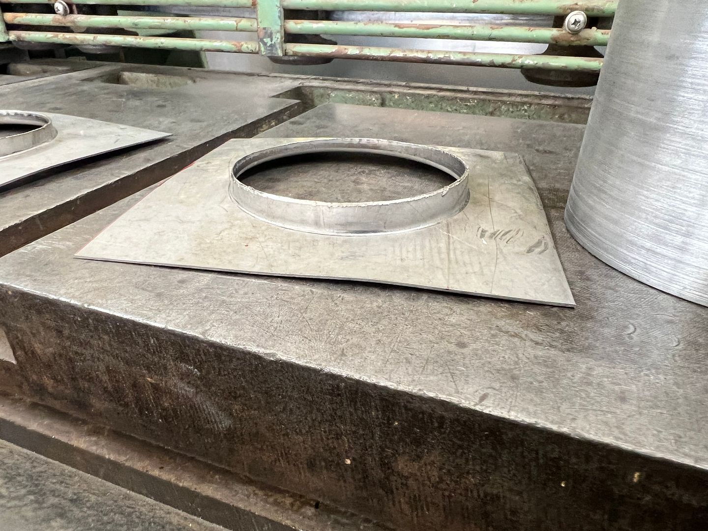
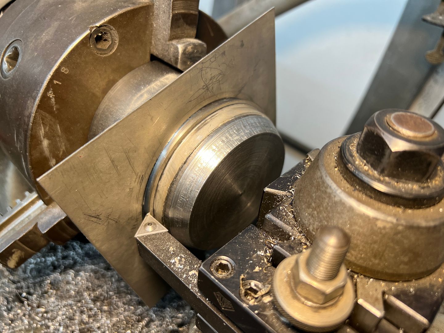
Back to the south bend to cut out our flange lip.. The punch was snug after the press operation, so it was used as a holding fixture for the trimming operation.
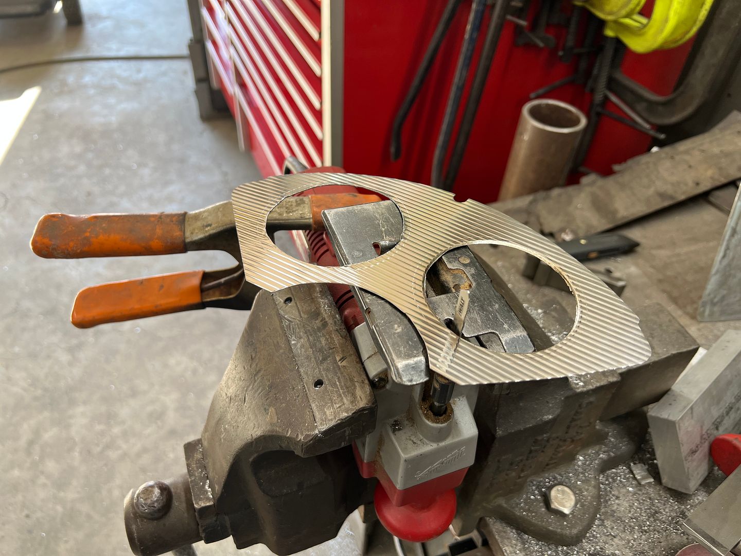
A holesaw in the drill press started the holes for the gauges and then we used our Jigsaw with cruise control to fine tune the openings.
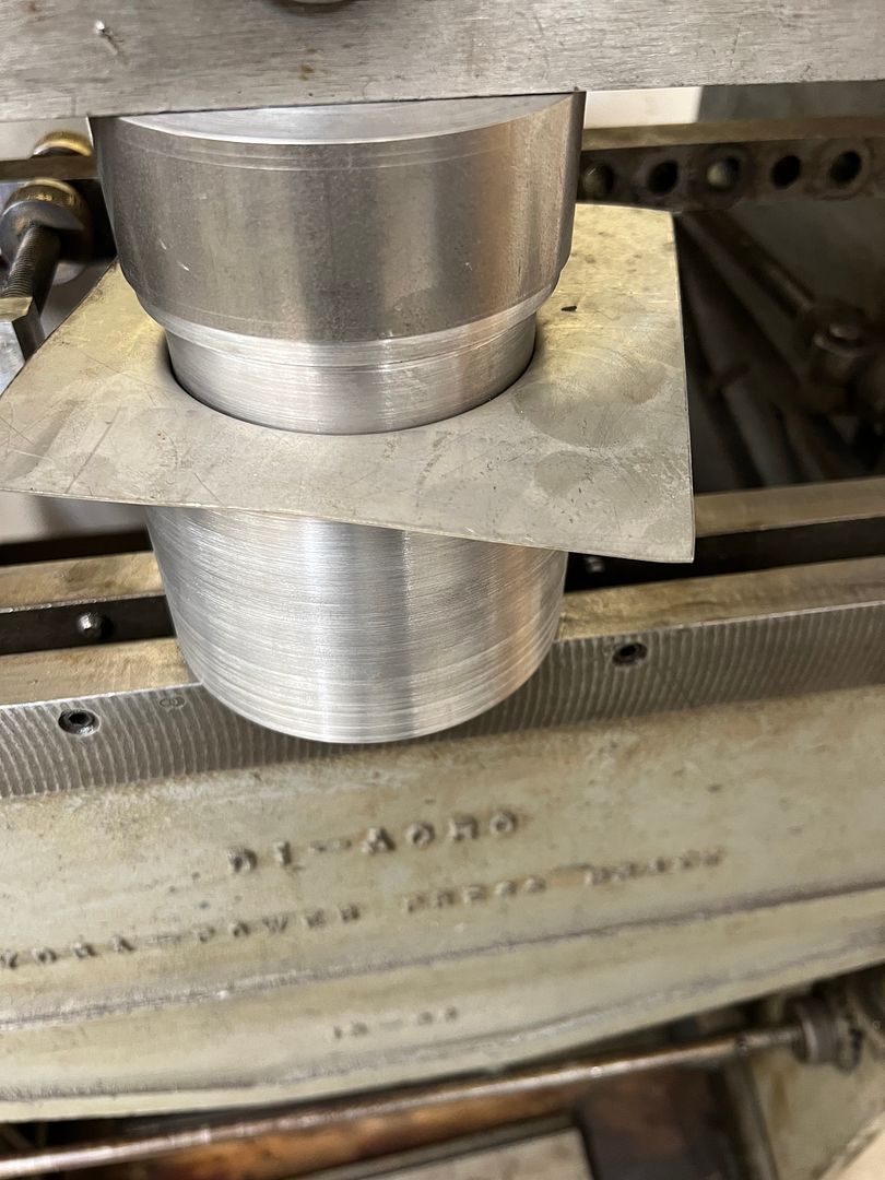
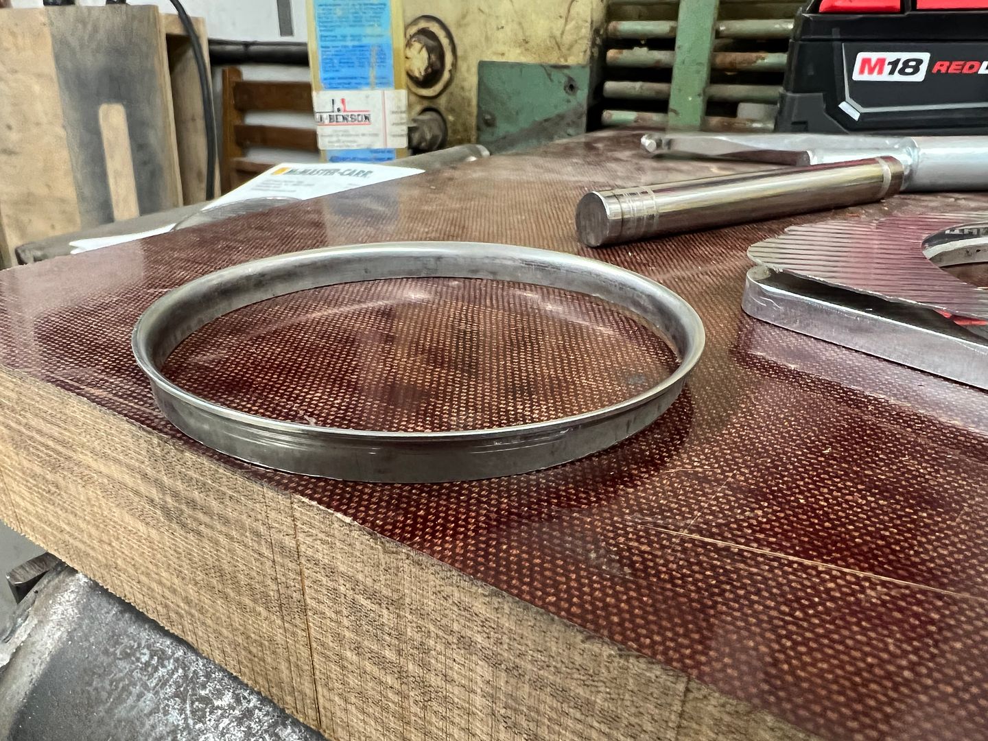
A sheet of phenolic gives us a non-marring surface to pound on, the Snap-on linear stretch hammer swages the flange over and a 1/2" diameter round makes a good punch to flatten out the rest.
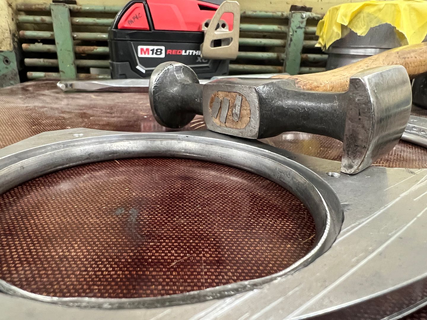

Finished "eyelets"
Still have to install the indicator lights, but since I need to pack up for the local car show tomorrow in Leonardtown, we'll finish that up this coming week.
......so let's make some stainless "eyelets" to both hold the ribbed stainless securely to the billet panel, as well as give us a finished edge around the cut hole.. First a punch and die will be needed to press one side of our eyelet.
and we added a 1/2 x 1/2 tang to hold the punch in the press brake...
Back to the south bend to cut out our flange lip.. The punch was snug after the press operation, so it was used as a holding fixture for the trimming operation.
A holesaw in the drill press started the holes for the gauges and then we used our Jigsaw with cruise control to fine tune the openings.
A sheet of phenolic gives us a non-marring surface to pound on, the Snap-on linear stretch hammer swages the flange over and a 1/2" diameter round makes a good punch to flatten out the rest.
Finished "eyelets"
Still have to install the indicator lights, but since I need to pack up for the local car show tomorrow in Leonardtown, we'll finish that up this coming week.
MJM
Promoted Users
Today we had a back up and punt moment. The nice chrome bezel on the gauges is far too large to fit in those corners of the instrument panel bezel from the outside. So we'll have to keep it on the backside, but that doesn't help us cover up the cut edge of the hole in the ribbed stainless..
......so let's make some stainless "eyelets" to both hold the ribbed stainless securely to the billet panel, as well as give us a finished edge around the cut hole.. First a punch and die will be needed to press one side of our eyelet.
and we added a 1/2 x 1/2 tang to hold the punch in the press brake...
Back to the south bend to cut out our flange lip.. The punch was snug after the press operation, so it was used as a holding fixture for the trimming operation.
A holesaw in the drill press started the holes for the gauges and then we used our Jigsaw with cruise control to fine tune the openings.
A sheet of phenolic gives us a non-marring surface to pound on, the Snap-on linear stretch hammer swages the flange over and a 1/2" diameter round makes a good punch to flatten out the rest.
Finished "eyelets"
Still have to install the indicator lights, but since I need to pack up for the local car show tomorrow in Leonardtown, we'll finish that up this coming week.
That pretty freaking trick!!! These
One of one pieces you fabricate must really get others to wonder where you bought those bitchin pieces.
Great job....
")
MP&C
Member
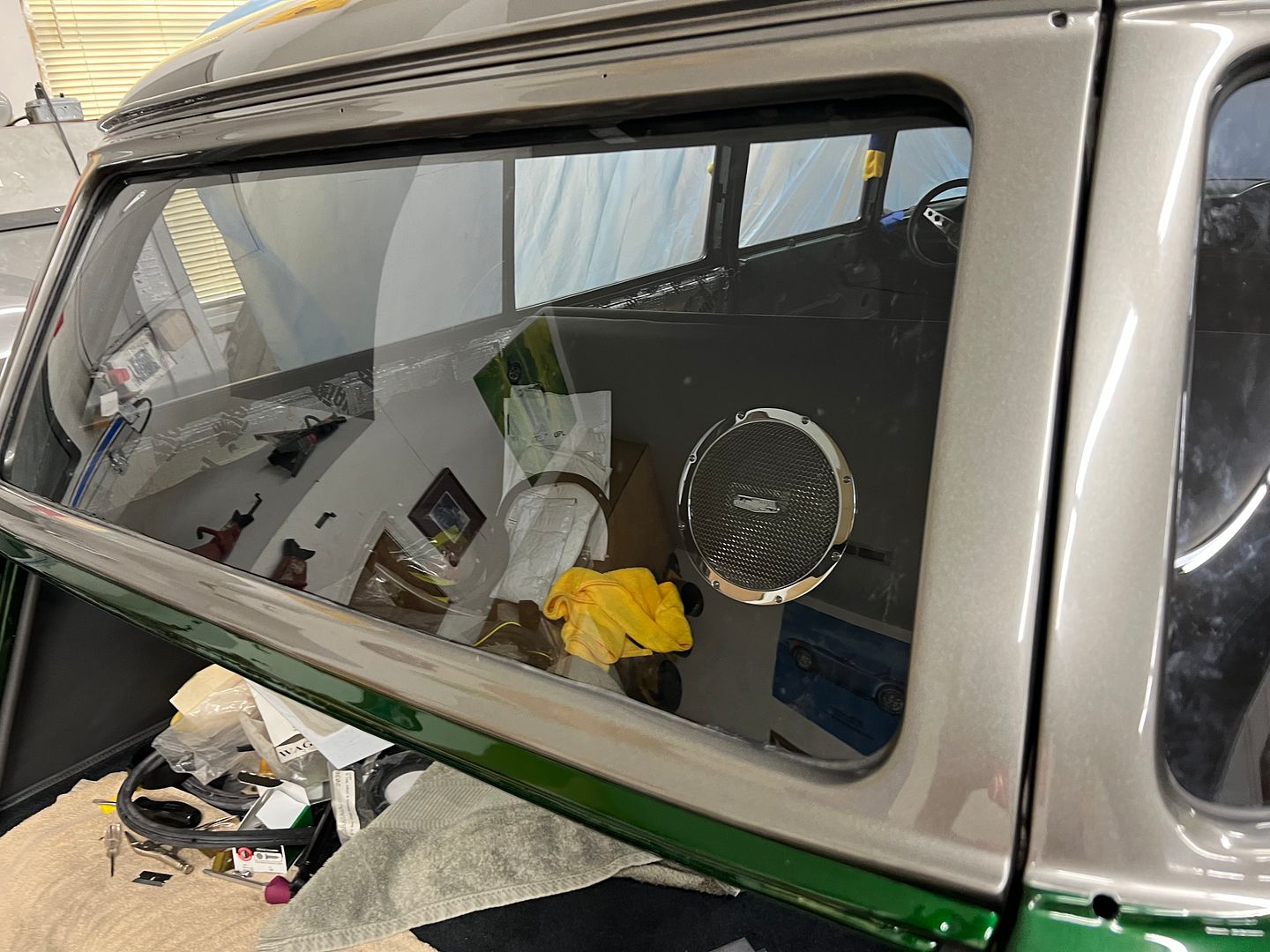
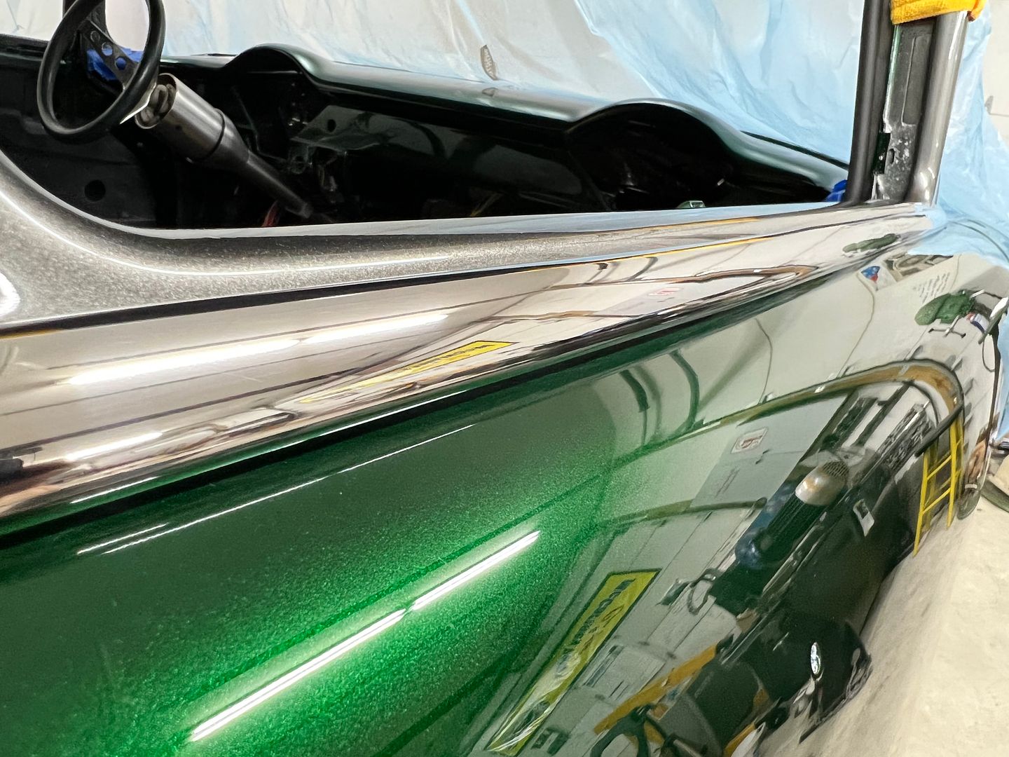
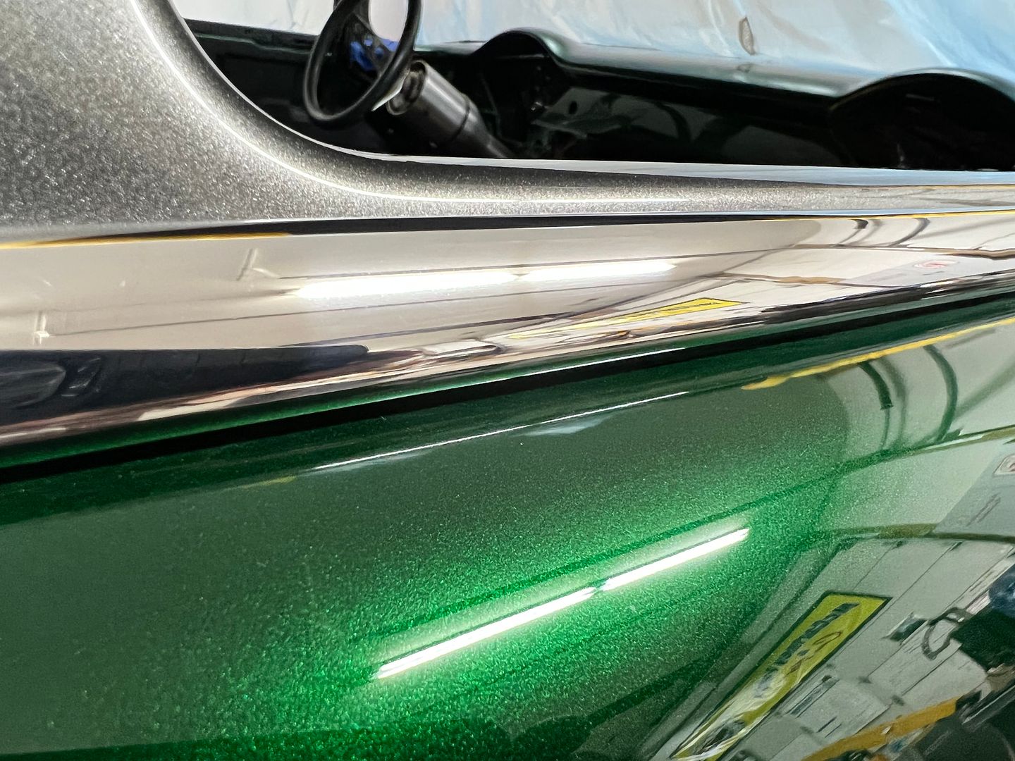
We did a test fit of the instrument panel in the car to see what it looked like with the green backdrop...
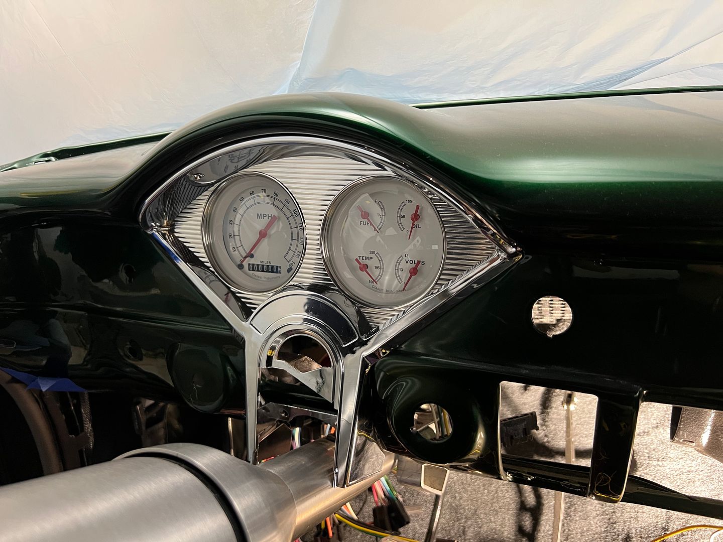
This stainless will be the same material used in the dash insert "band" that goes from side to side, as well as the insert for the console. Should add some pizazz to the interior... Here's the view with our Alpinetech indicator lights added....
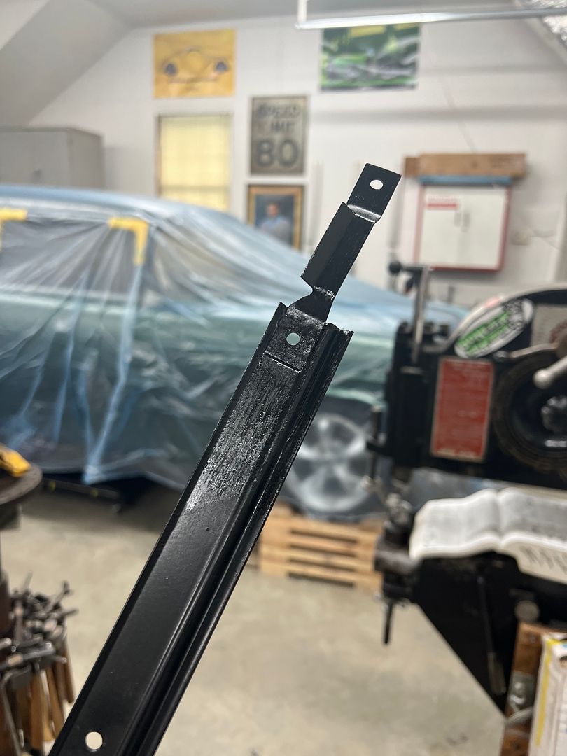
Our OEM retainers for the bottom of the curved side glass had one piece with a bracket broken off. These brackets serve as a place to screw/attach the garnish moldings.
The broken piece was removed and the spot welds ground smooth...
A new piece was cut out of some 19 ga steel and the Diacro press brake made short work of repeating 45* bends.
The new part was media blasted, TIG welder used to plug weld things back together, more media blasting and some epoxy mixed up and brushed on using an acid brush.
On to our glass installation, we had picked up some 3M strip-calk to seal the rubber to the glass.
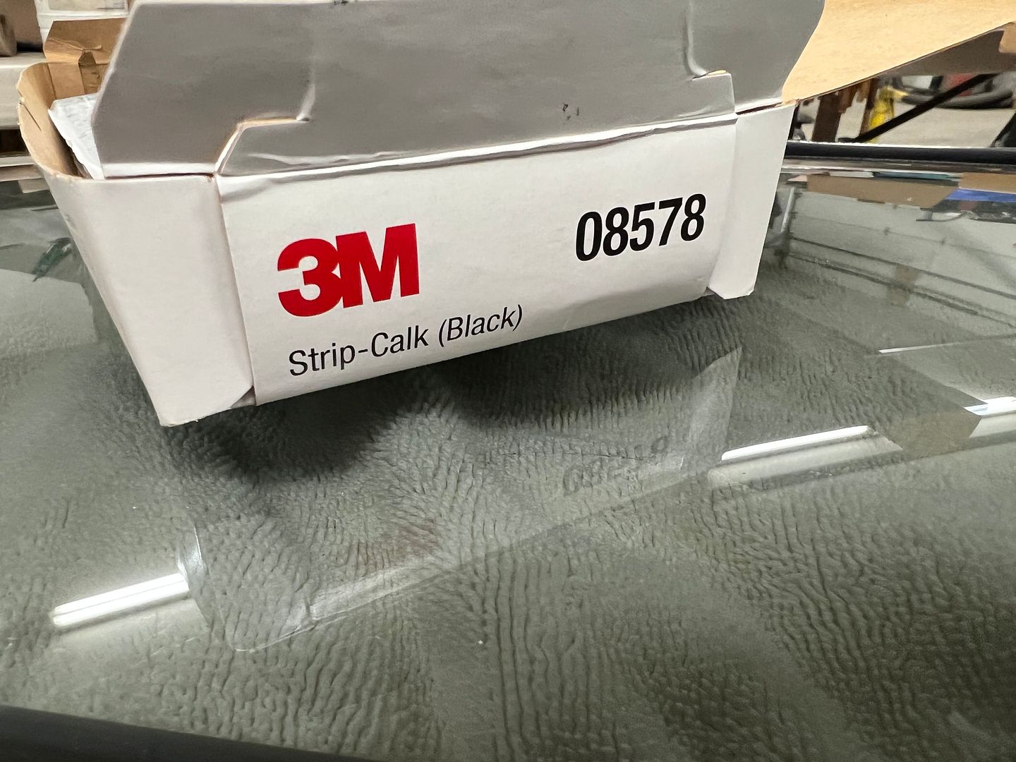
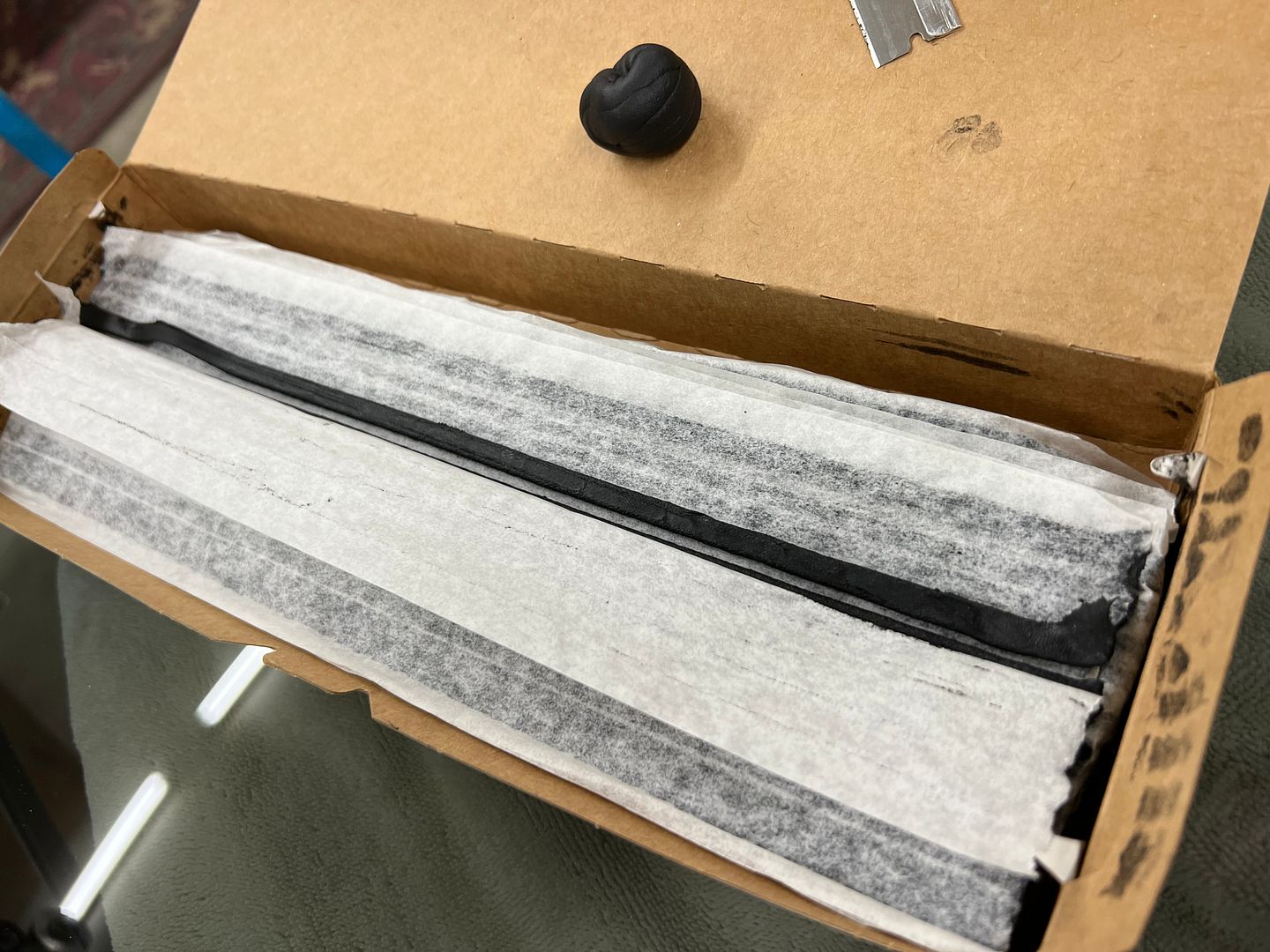
We found that the full width strip provided a bit too much and some oozage ensued... First is always the messy one, right?
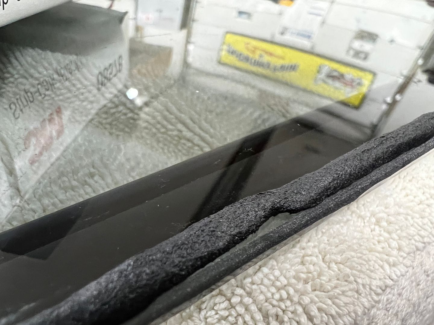
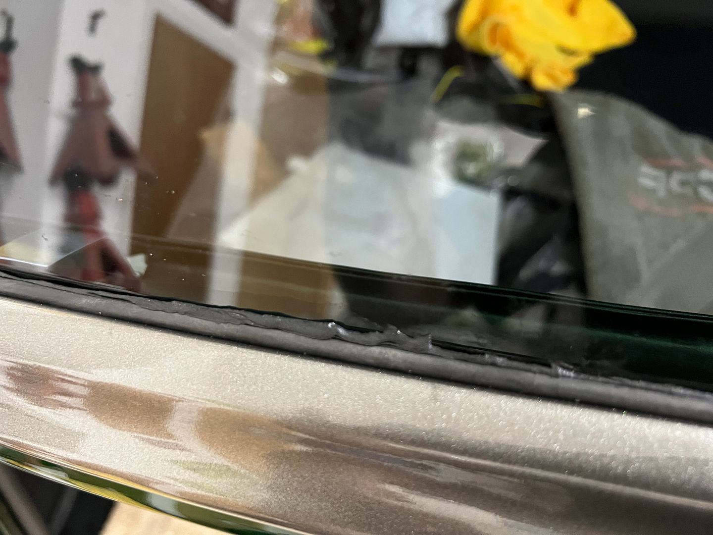
So we laid the following ones on the glass and cut down the middle for a more narrow strip.. More better....
So then a person gets cocky and needs a reality check on the driver's side....
As good a stopping point as any..
This stainless will be the same material used in the dash insert "band" that goes from side to side, as well as the insert for the console. Should add some pizazz to the interior... Here's the view with our Alpinetech indicator lights added....
Our OEM retainers for the bottom of the curved side glass had one piece with a bracket broken off. These brackets serve as a place to screw/attach the garnish moldings.
The broken piece was removed and the spot welds ground smooth...
A new piece was cut out of some 19 ga steel and the Diacro press brake made short work of repeating 45* bends.
The new part was media blasted, TIG welder used to plug weld things back together, more media blasting and some epoxy mixed up and brushed on using an acid brush.
On to our glass installation, we had picked up some 3M strip-calk to seal the rubber to the glass.
We found that the full width strip provided a bit too much and some oozage ensued... First is always the messy one, right?
So we laid the following ones on the glass and cut down the middle for a more narrow strip.. More better....
So then a person gets cocky and needs a reality check on the driver's side....
As good a stopping point as any..
MP&C
Member
OK, long overdue for an update..
Playing some more with our dash insert, this should look good..
We attempted different processes for folding the hemmed edge trim, but alas none gave a good consistent finish.
So some stainless strips were dropped off at Triton metals, a local machine shop we have used before... They will get much better results, still waiting on completion.
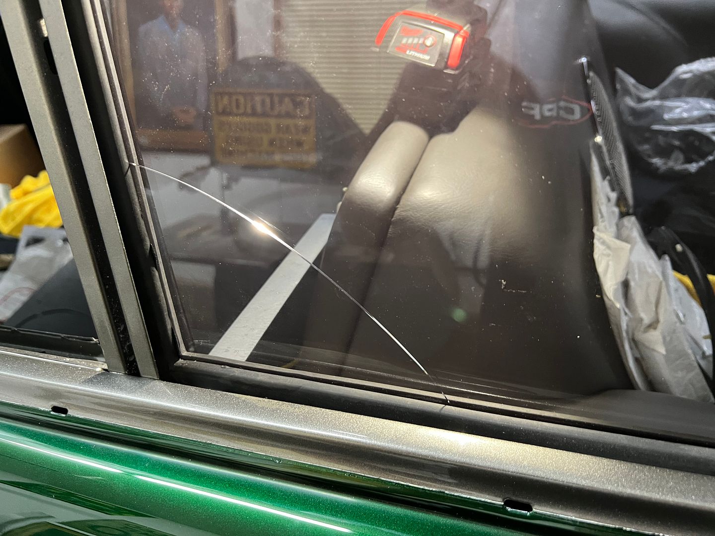
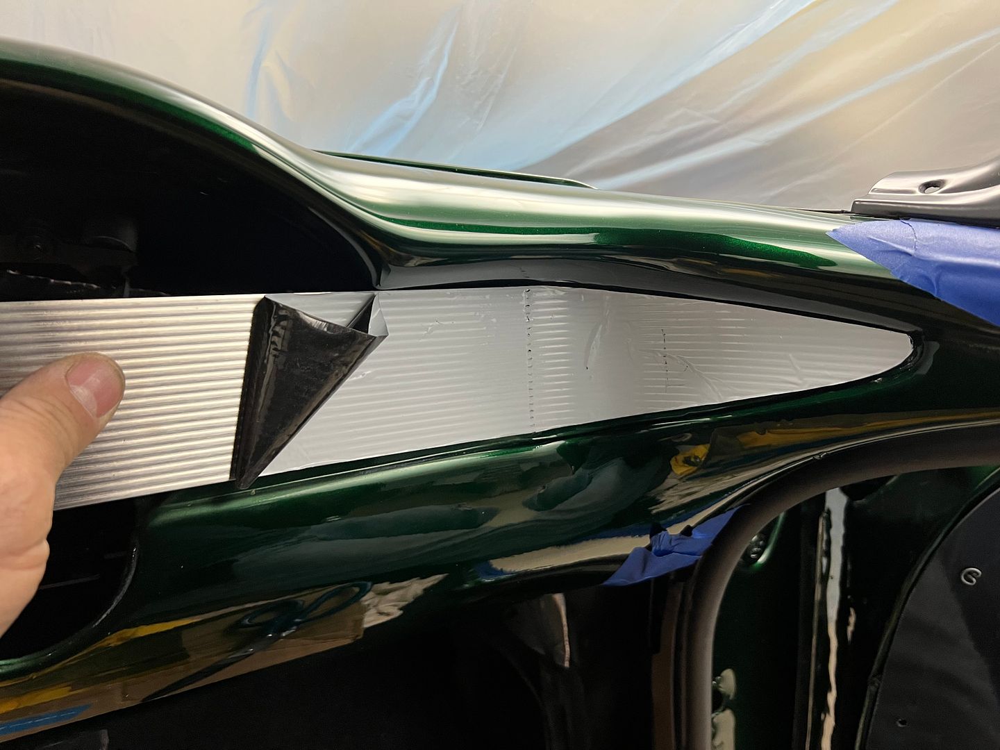
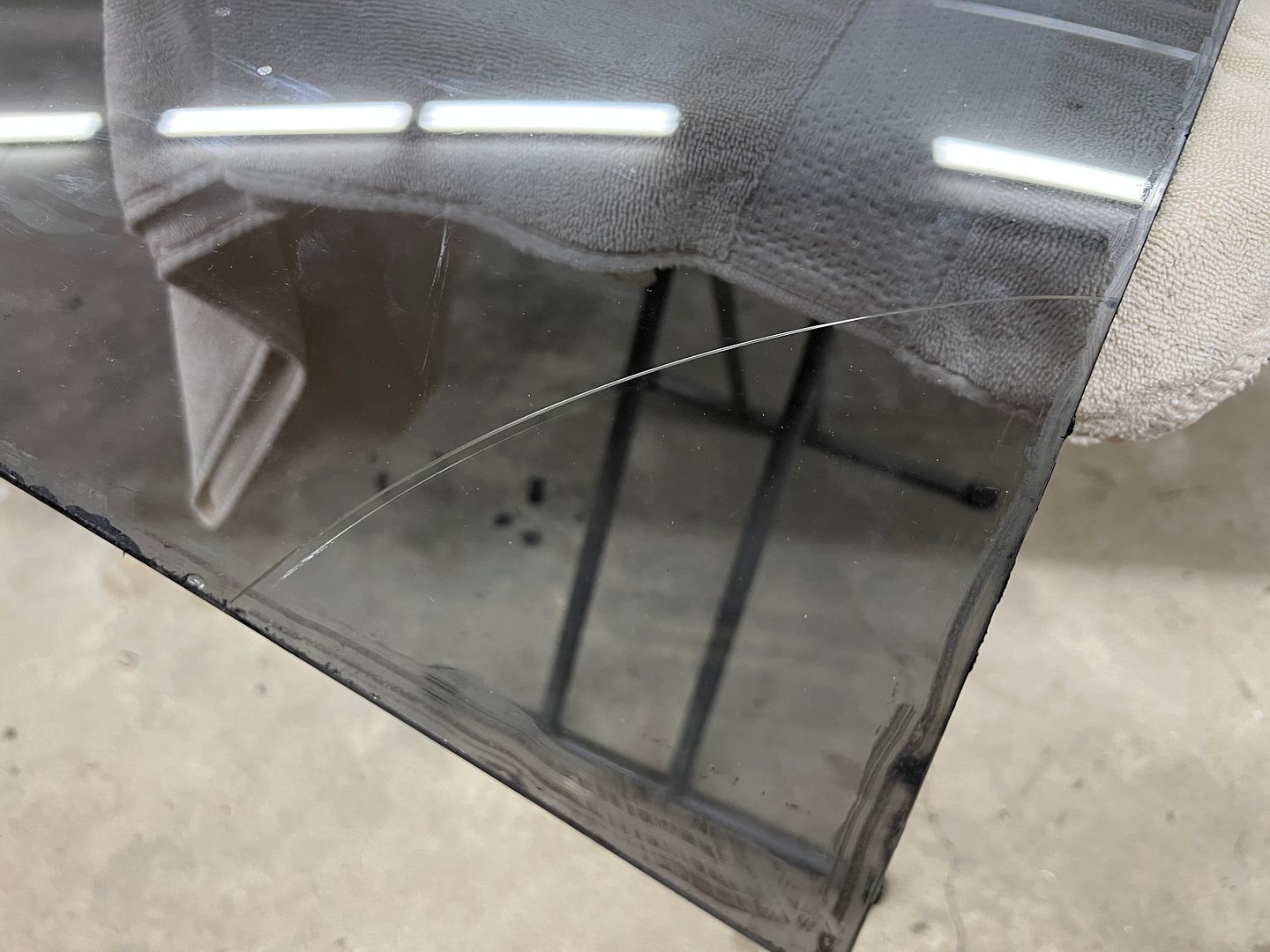
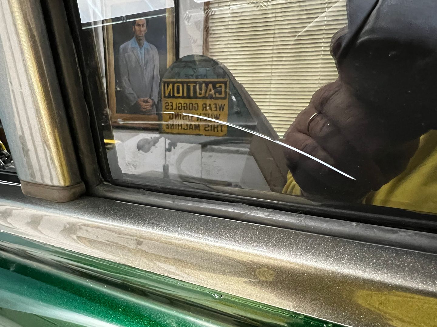
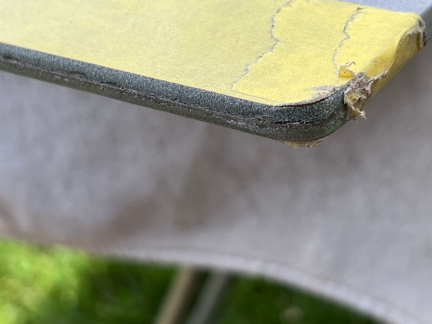
Back to our problem child of a window, this crack occurred as I slightly pried rearward with a metal rule. Exactly where I pried.
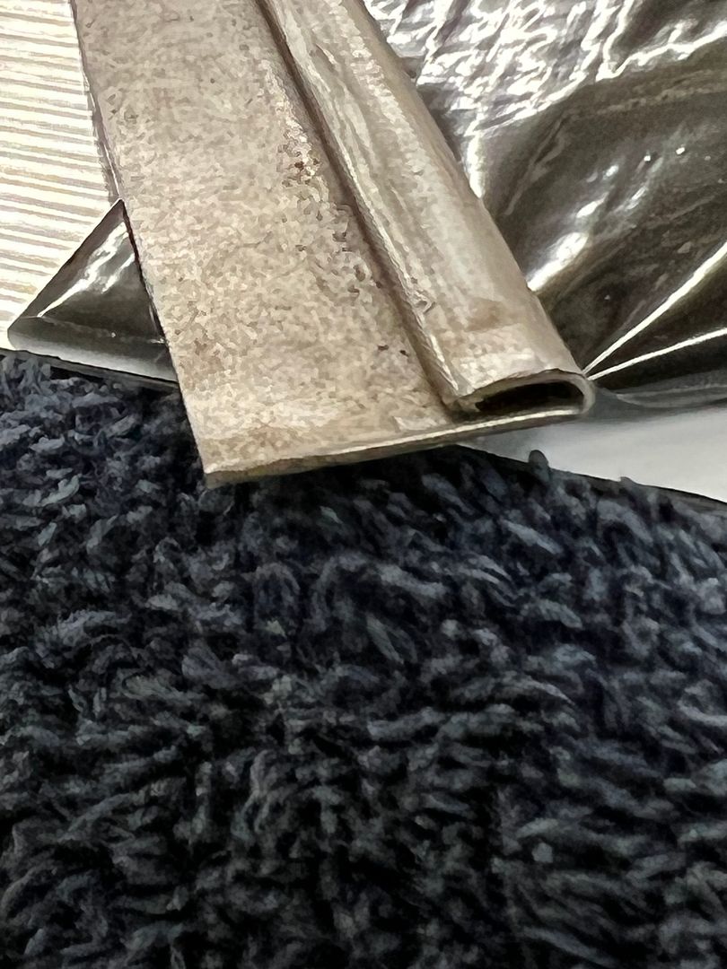
To limit the excess squeezed out of the seals on our next glass, we took the 3M strip-calk in its original form and sliced right down the middle..
Here's a video showing installation of the strip-calk, and another with installation of the seal over the strip-calk.
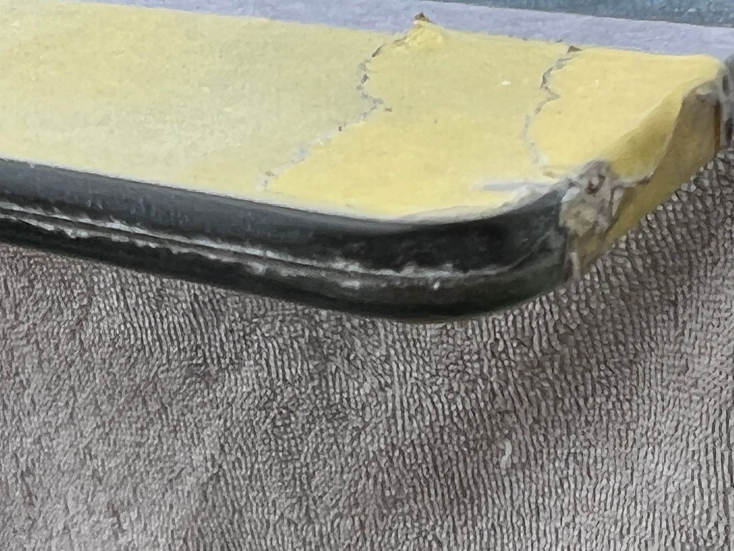
Installing window #2, we had a slight tight area and I asked Jared to push outward and that's when we had a repeat of Groundhog Day..
So, maybe the pry the first time was not the only issue. Fast forward so we can look back, last night we did a dry fit of the garnish moldings around these windows and found that the tack strips holding the headliner were far too thick and pushed the moldings down so far that the back side would be visible through the glass. In addition, this was also pushing downward on the window and seal while we were attempting the installation. When we had installed the quarter panel previously, we used plug welds inside this window opening and some had a slight proud. Nothing that I was concerned with at the time and considering had the tack strip been the correct thickness it likely wouldn't have been an issue now. But with the headliner pushing downward, the seal was hanging up on one of the plug welds as Jared was pushing outward on the corner, which made a perfect fulcrum effect for crack #2. Since we aren't pulling a headliner out, we went ahead and cleaned up the plug welds. This meant taping off all the nice pretty paint on the outside and the interior as well..
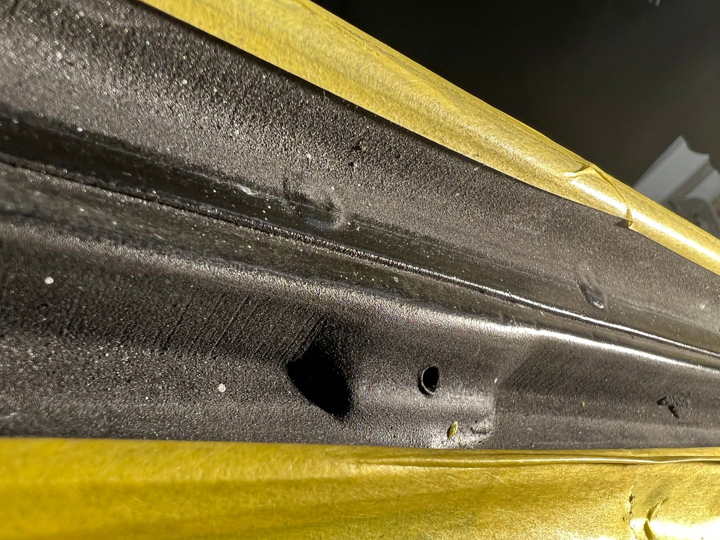
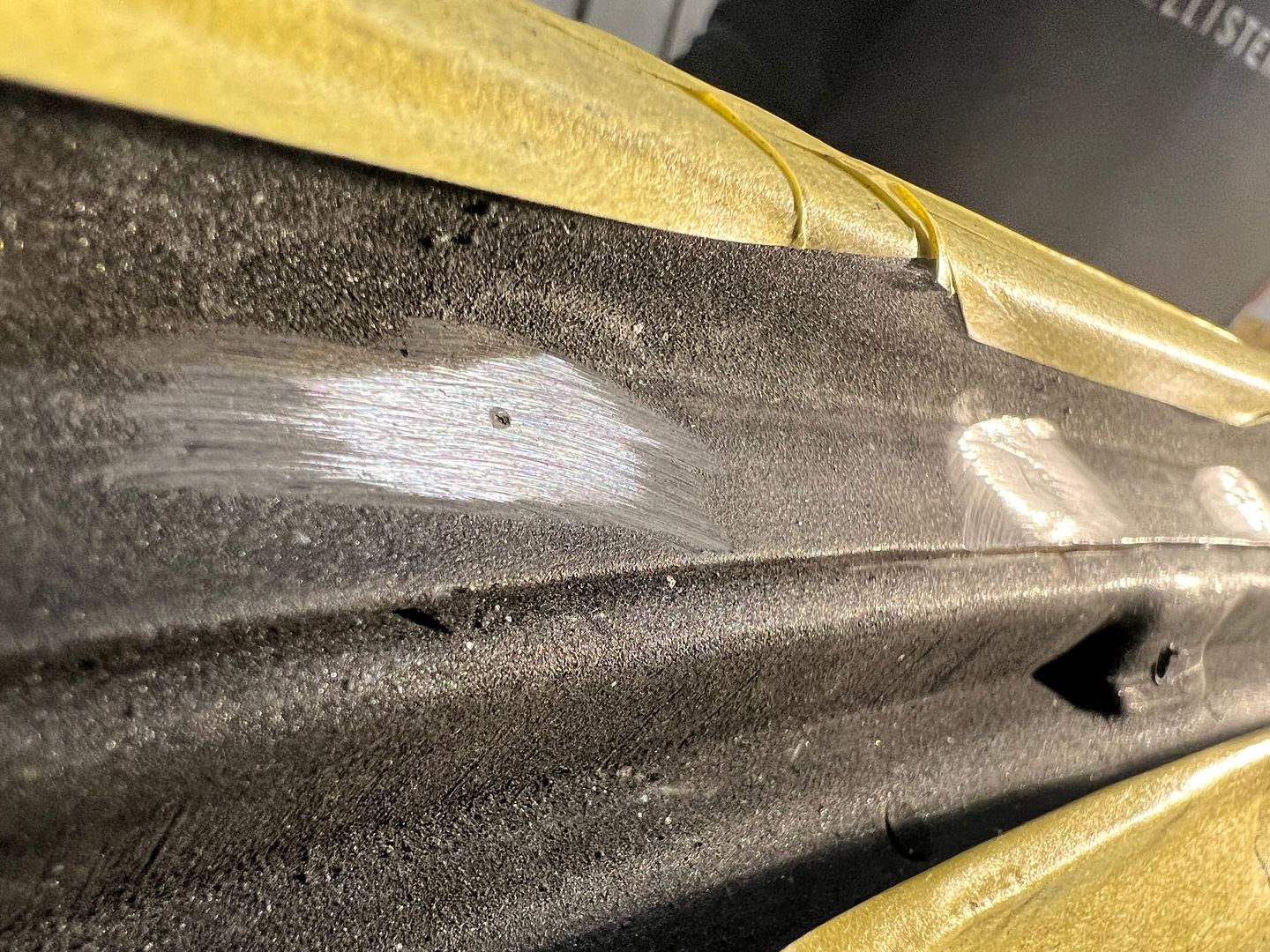
All of the welds cleaned up, we mixed up some SPI epoxy and used a small brush to add three coats on the bare areas. And to counter the effect of the garnish molding hanging too low, we will now need to make some one-off upper clips that are half height of the ones we just ordered (and have been waiting 4 months to arrive), in order to get the molding up and out of sight when looking through the glass. Story of my life..
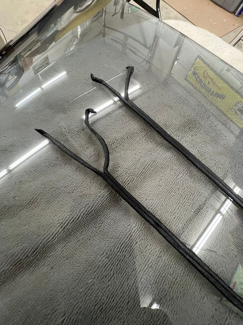
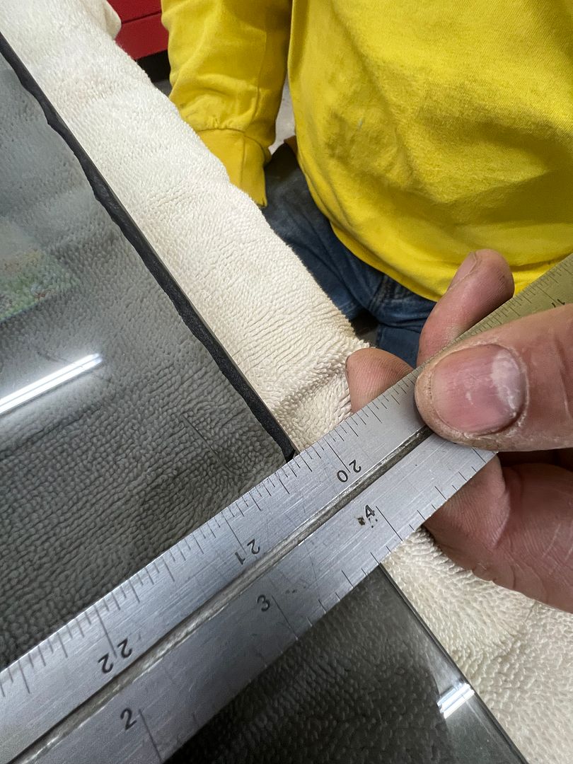
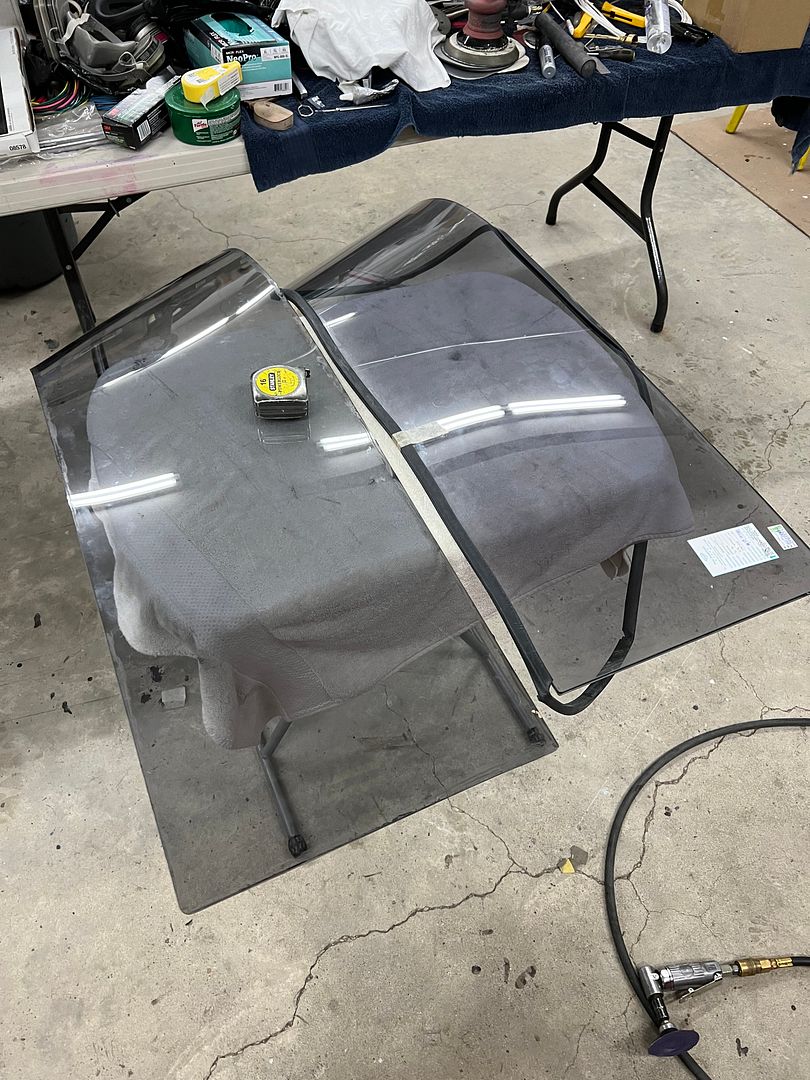
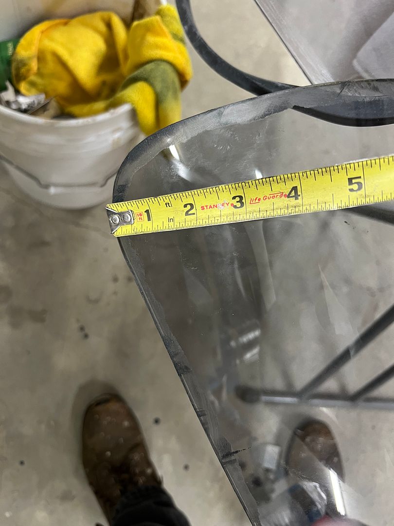
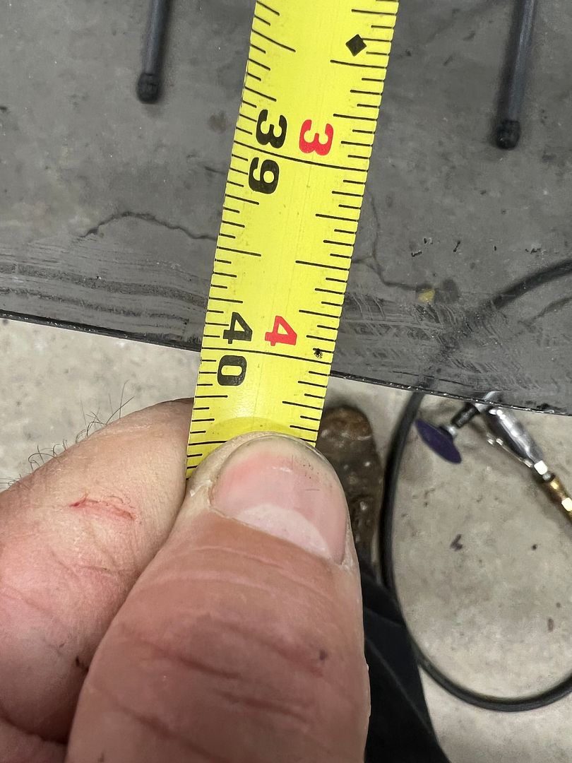
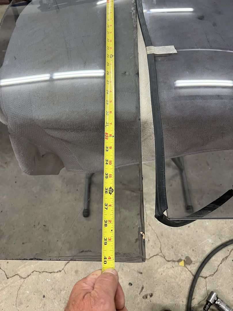
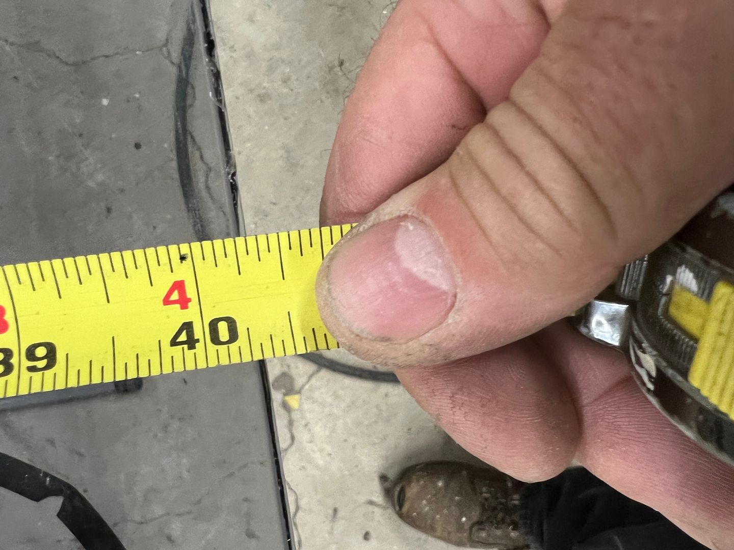
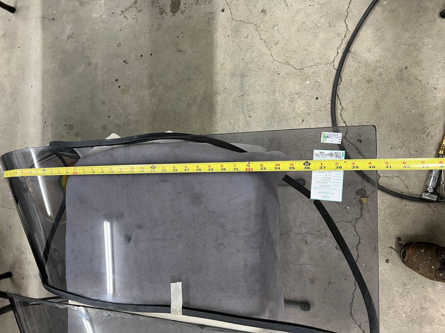
Window #3!! We had length issues from the last replacement, let's check this one as well. Hooking our tape measure on the apex of the pointy end, the original ordered with the rest of the glass set shows to be 40-1/16 in length. The new replacement, like the last one (#2), was 40-5/16. So we have a 1/4" to remove.
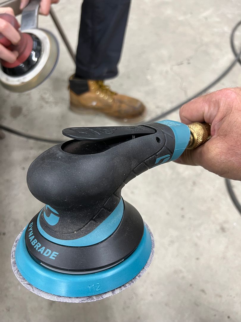
So we consulted my glass expert John Glenn the last time we did this, and got the rundown of the various methods we could possibly use. Since I'm more of a go slow and sneak up on the end goal, I opted for using Cubitron belts on our Dynabride sander. It did a better job of taking down corners so we followed the process discussed in the next video. Then when we had reached the size needed (three hours later), a 320 grit disc on the DA gave a more polished appearance.
Our installation last night went in relatively painless and crack free. Now to make some upper clips..
Playing some more with our dash insert, this should look good..
We attempted different processes for folding the hemmed edge trim, but alas none gave a good consistent finish.
So some stainless strips were dropped off at Triton metals, a local machine shop we have used before... They will get much better results, still waiting on completion.
Back to our problem child of a window, this crack occurred as I slightly pried rearward with a metal rule. Exactly where I pried.
To limit the excess squeezed out of the seals on our next glass, we took the 3M strip-calk in its original form and sliced right down the middle..
Here's a video showing installation of the strip-calk, and another with installation of the seal over the strip-calk.
Installing window #2, we had a slight tight area and I asked Jared to push outward and that's when we had a repeat of Groundhog Day..
So, maybe the pry the first time was not the only issue. Fast forward so we can look back, last night we did a dry fit of the garnish moldings around these windows and found that the tack strips holding the headliner were far too thick and pushed the moldings down so far that the back side would be visible through the glass. In addition, this was also pushing downward on the window and seal while we were attempting the installation. When we had installed the quarter panel previously, we used plug welds inside this window opening and some had a slight proud. Nothing that I was concerned with at the time and considering had the tack strip been the correct thickness it likely wouldn't have been an issue now. But with the headliner pushing downward, the seal was hanging up on one of the plug welds as Jared was pushing outward on the corner, which made a perfect fulcrum effect for crack #2. Since we aren't pulling a headliner out, we went ahead and cleaned up the plug welds. This meant taping off all the nice pretty paint on the outside and the interior as well..
All of the welds cleaned up, we mixed up some SPI epoxy and used a small brush to add three coats on the bare areas. And to counter the effect of the garnish molding hanging too low, we will now need to make some one-off upper clips that are half height of the ones we just ordered (and have been waiting 4 months to arrive), in order to get the molding up and out of sight when looking through the glass. Story of my life..
Window #3!! We had length issues from the last replacement, let's check this one as well. Hooking our tape measure on the apex of the pointy end, the original ordered with the rest of the glass set shows to be 40-1/16 in length. The new replacement, like the last one (#2), was 40-5/16. So we have a 1/4" to remove.
So we consulted my glass expert John Glenn the last time we did this, and got the rundown of the various methods we could possibly use. Since I'm more of a go slow and sneak up on the end goal, I opted for using Cubitron belts on our Dynabride sander. It did a better job of taking down corners so we followed the process discussed in the next video. Then when we had reached the size needed (three hours later), a 320 grit disc on the DA gave a more polished appearance.
Our installation last night went in relatively painless and crack free. Now to make some upper clips..
Last edited:
MJM
Promoted Users
Man oh man, I literally got an uneasy feeling in my stomach reading about the 2nd piece of glass. I almost stopped reading when I got to the third piece of glass. I couldn't bare to read it happened again. I'm relieved, as I'm sure you are the third glass worked out after your investigation to find the root cause of "why" it was happening, well done!
Thanks for the pro tip on how to sand edges of glass. Hopefully I won't ever need it but, good information to have.
Thanks for sharing.
Mike
Thanks for the pro tip on how to sand edges of glass. Hopefully I won't ever need it but, good information to have.
Thanks for sharing.
Mike
MP&C
Member
One expensive lesson we learned from installing a window three times, the tack strip that the owner bought was too thick for the headliner, and as a side effect cramped the glass going in. This also meant the upper window clips, which also serve to "position" the garnish molding, pushed the molding down far enough that the back side was visible through the glass.
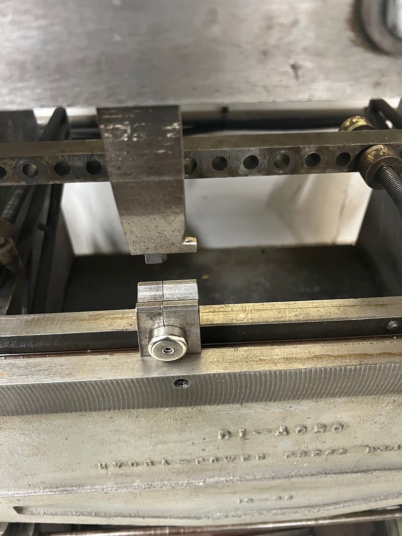
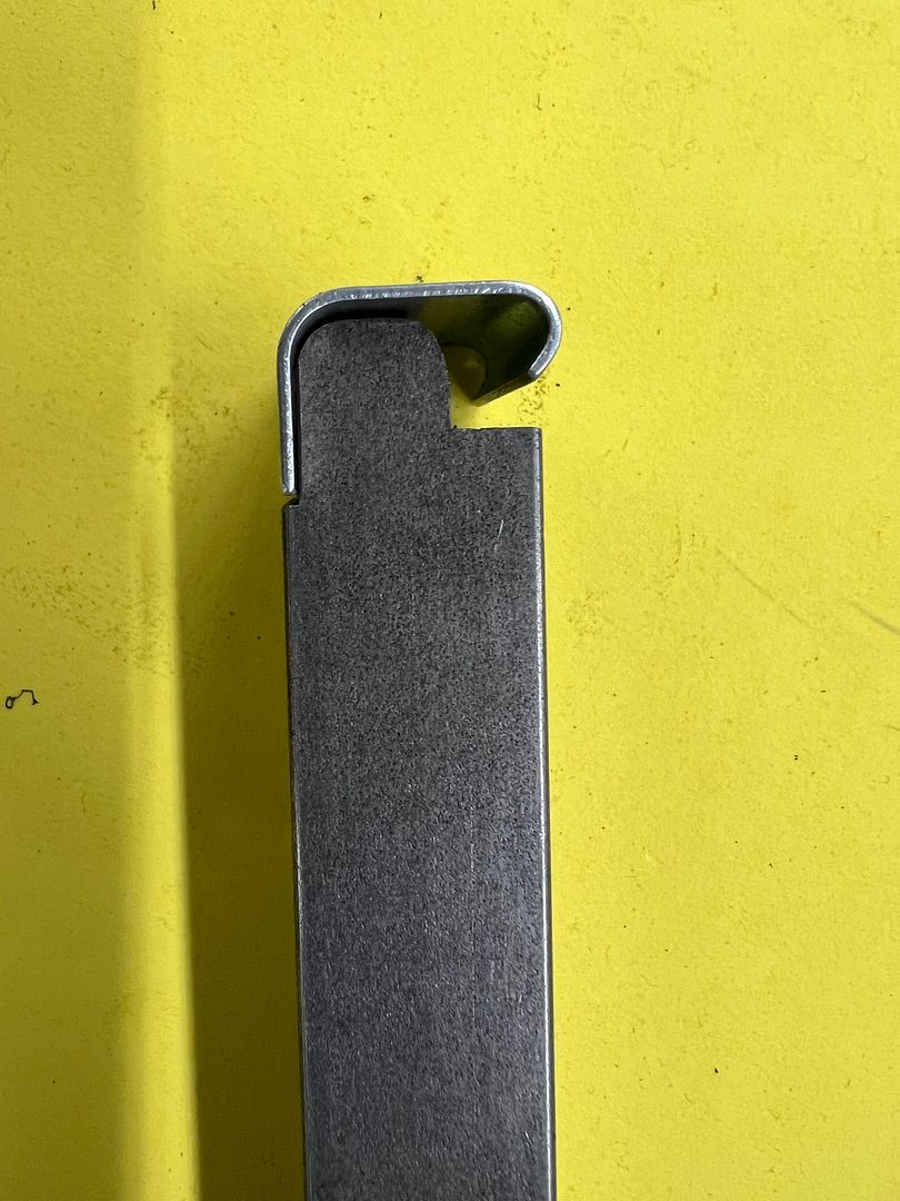
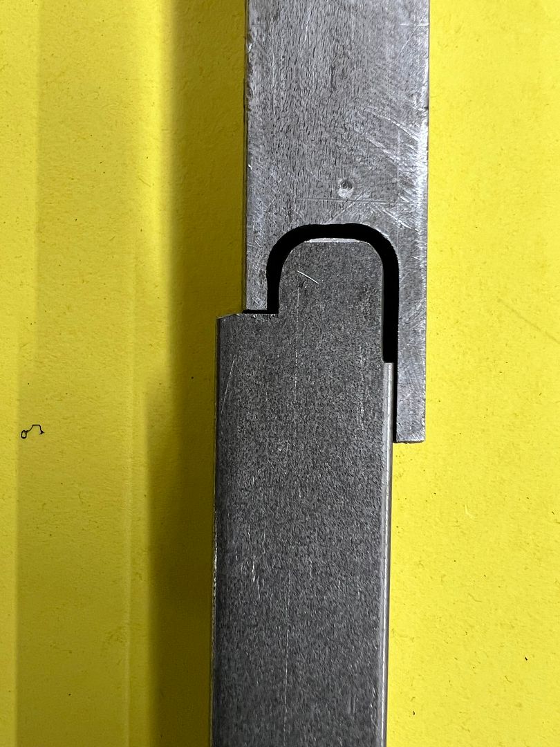
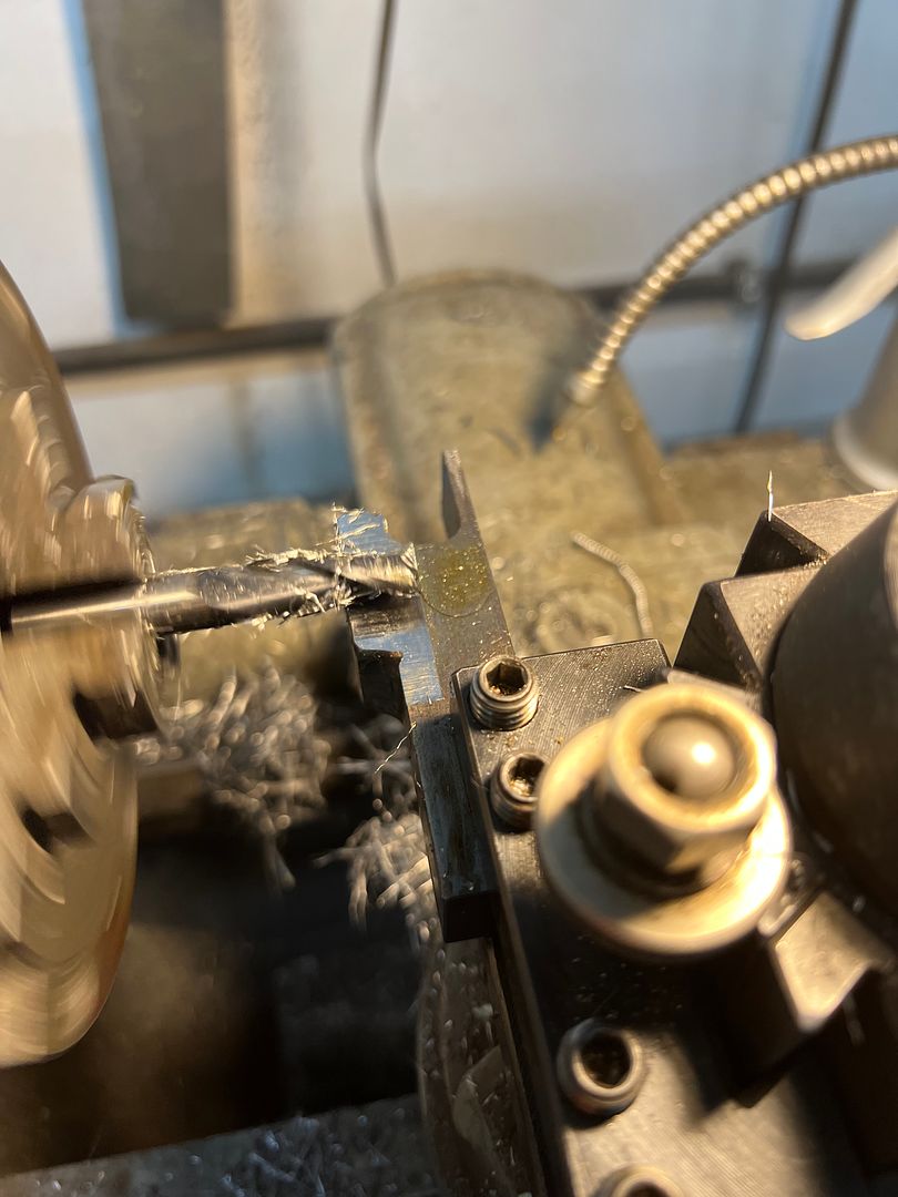
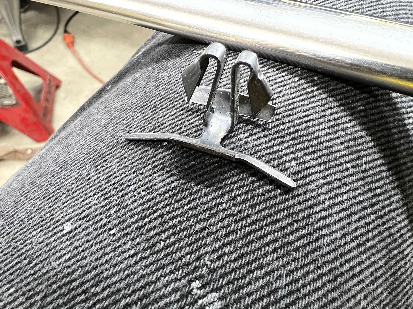
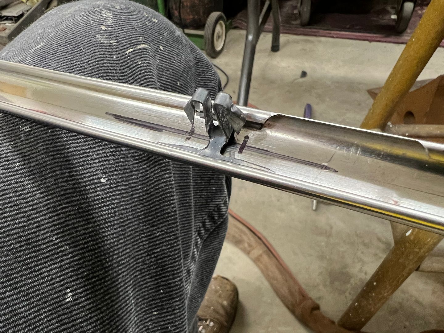
In order to remedy that view through the glass, we need to fabricate new clips that allow the trim to position higher on the glass. We start with a set of dies for the Lennox so we can make a run of the needed shape, and then cut them individually to size. This should give us the best consistency on size. Our first set of dies will take a folded 90* shape and form it into a "U" shape. We used the Southbend "milling machine" to provide a relief for the long side flange of the clip.
Additional reliefs and some roloc sander action and we have the lower die ready for the shortened clip.
Then our 3/8 end mill is brought in from the end to form a matching profile.
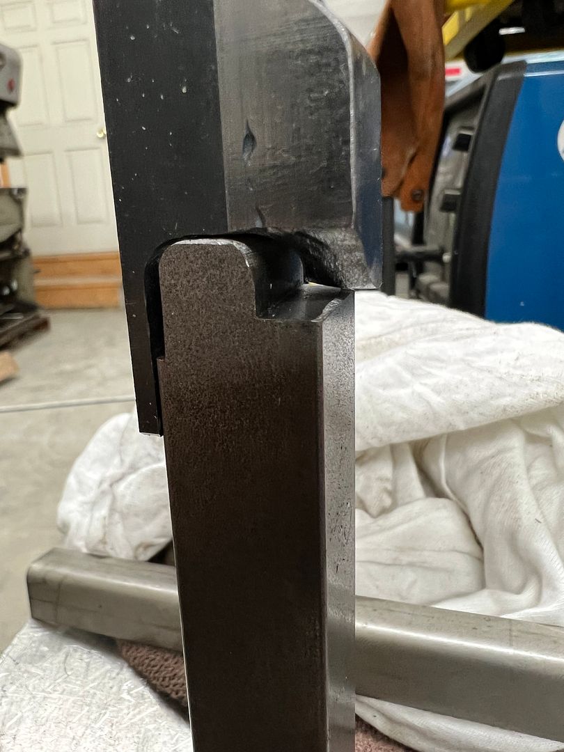
A piece of 1018 is welded onto the side to give us more "meat" to make the folding ramp, and then machined to clean up the weld.
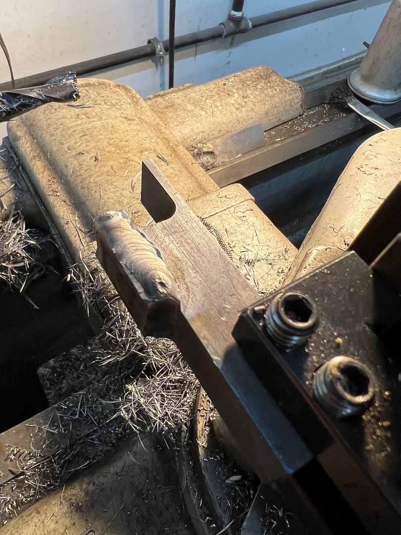
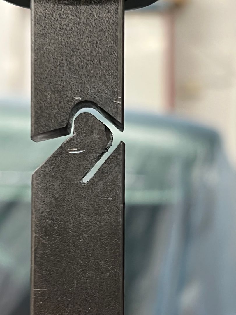
Using the pneumatic belt sander and a cone shaped die grinder we add the ramp to the upper die and then run a profile through..
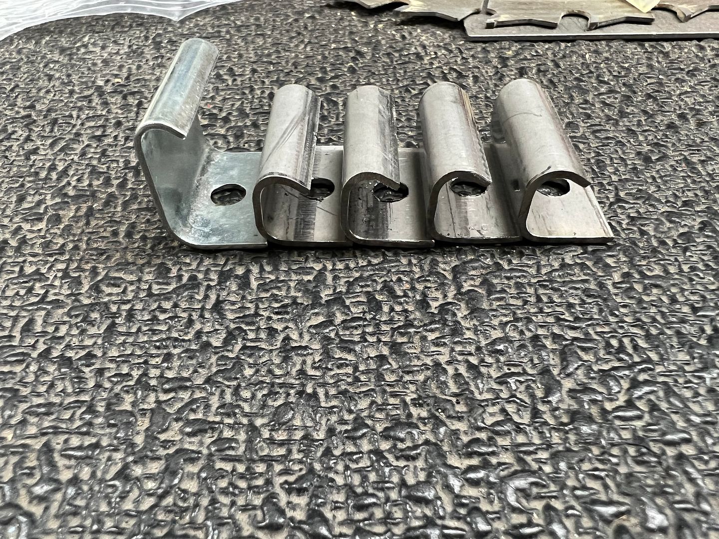
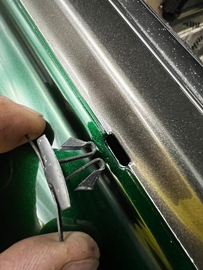
Our next set of dies for the wrap around fold....
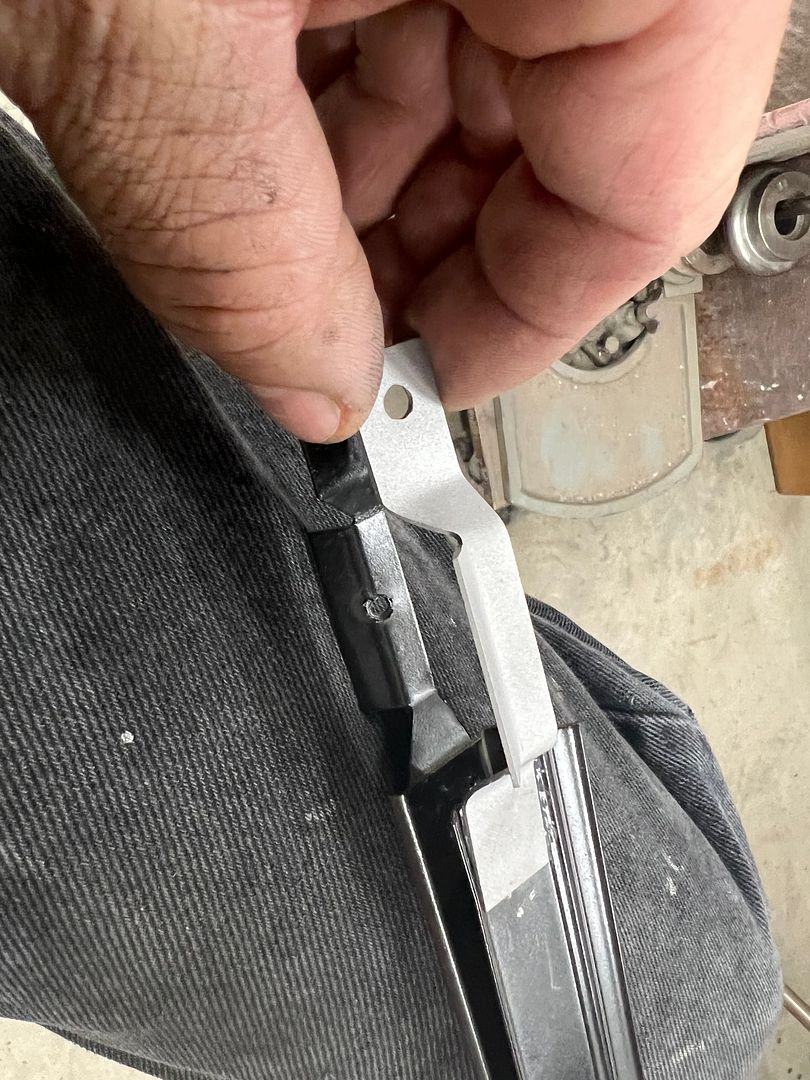
Clips cut to length and mounting holes drilled
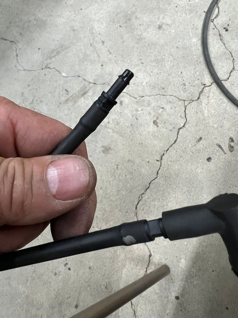
Next on the list was to install the new wiper washer nozzles on my daily, since the old ones couldn't stand the heat under the hood with a turbo. The barb fitting had broken free of the nozzle and we no longer had windshield cleaning service. Upon removal, I found that one of the barb couplings had disintegrated as well. And here we were one hour after the auto parts stores had closed. Here's a still intact sample:
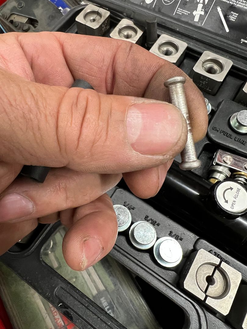
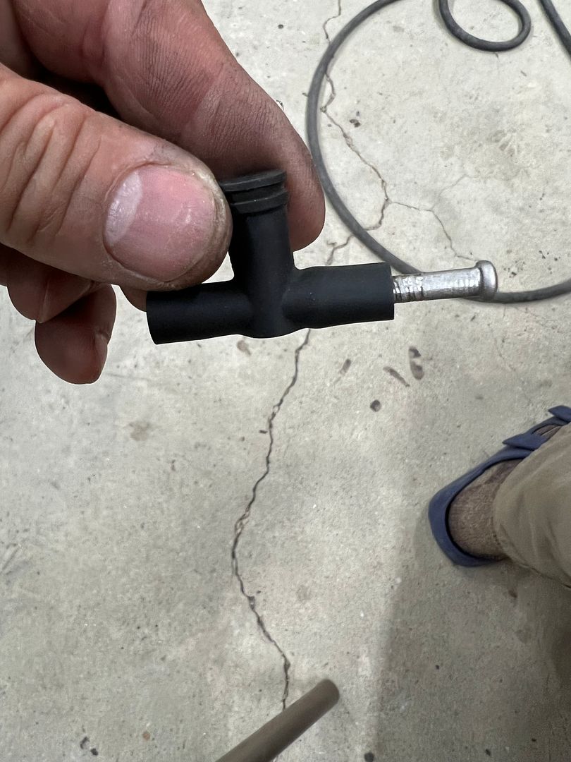
Since we had some stainless brake line left over from the wagon, lets make some lemonade...
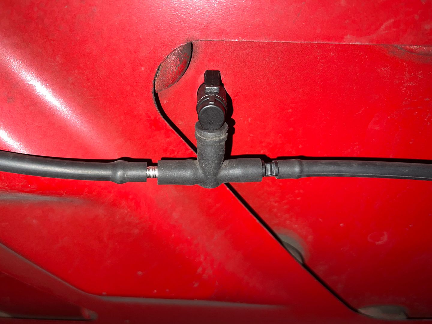
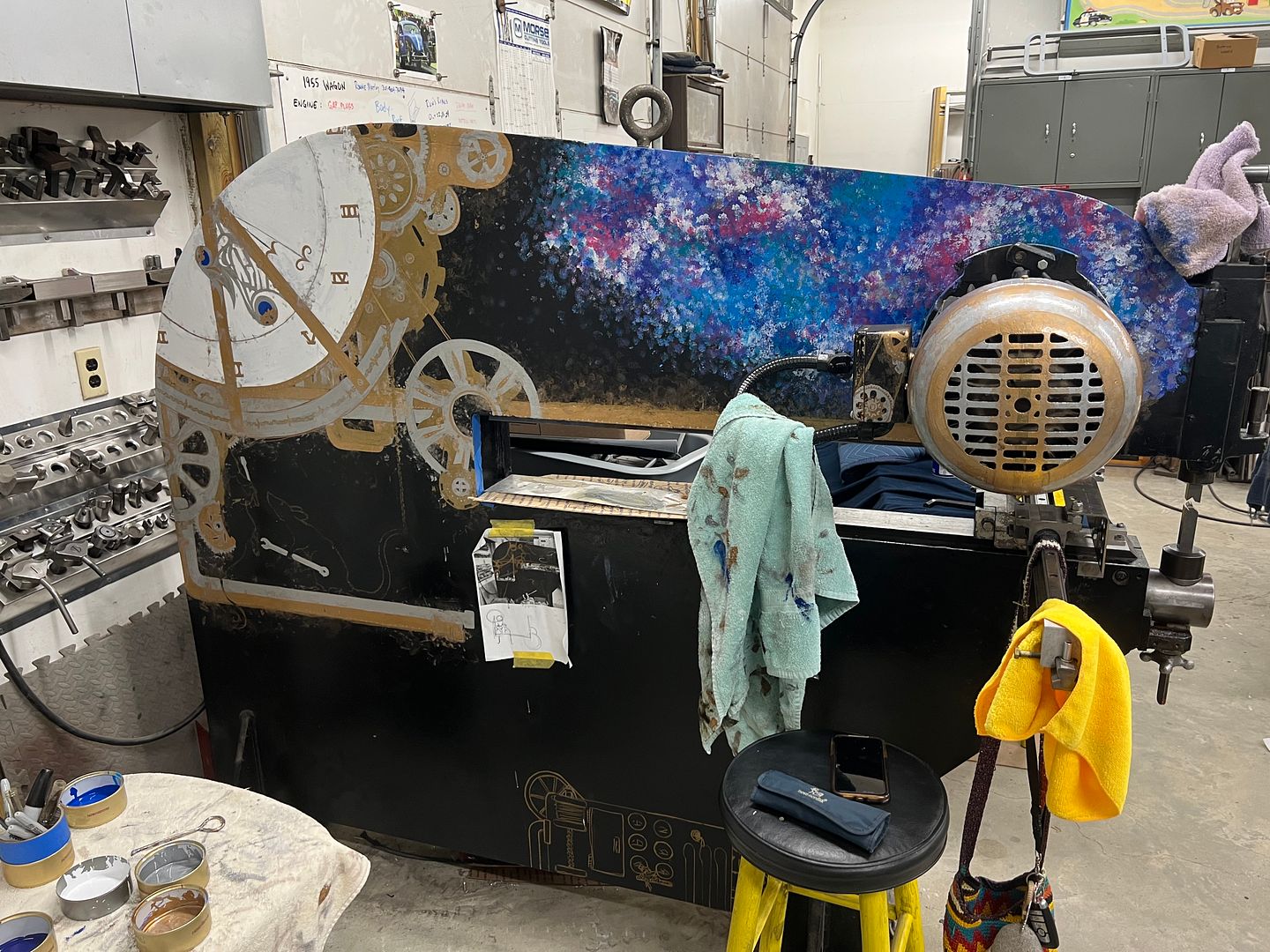
Back in business.. And the artist has made some progress on the Lennox....
In order to remedy that view through the glass, we need to fabricate new clips that allow the trim to position higher on the glass. We start with a set of dies for the Lennox so we can make a run of the needed shape, and then cut them individually to size. This should give us the best consistency on size. Our first set of dies will take a folded 90* shape and form it into a "U" shape. We used the Southbend "milling machine" to provide a relief for the long side flange of the clip.
Additional reliefs and some roloc sander action and we have the lower die ready for the shortened clip.
Then our 3/8 end mill is brought in from the end to form a matching profile.
A piece of 1018 is welded onto the side to give us more "meat" to make the folding ramp, and then machined to clean up the weld.
Using the pneumatic belt sander and a cone shaped die grinder we add the ramp to the upper die and then run a profile through..
Our next set of dies for the wrap around fold....
Clips cut to length and mounting holes drilled
Next on the list was to install the new wiper washer nozzles on my daily, since the old ones couldn't stand the heat under the hood with a turbo. The barb fitting had broken free of the nozzle and we no longer had windshield cleaning service. Upon removal, I found that one of the barb couplings had disintegrated as well. And here we were one hour after the auto parts stores had closed. Here's a still intact sample:
Since we had some stainless brake line left over from the wagon, lets make some lemonade...
Back in business.. And the artist has made some progress on the Lennox....
MP&C
Member
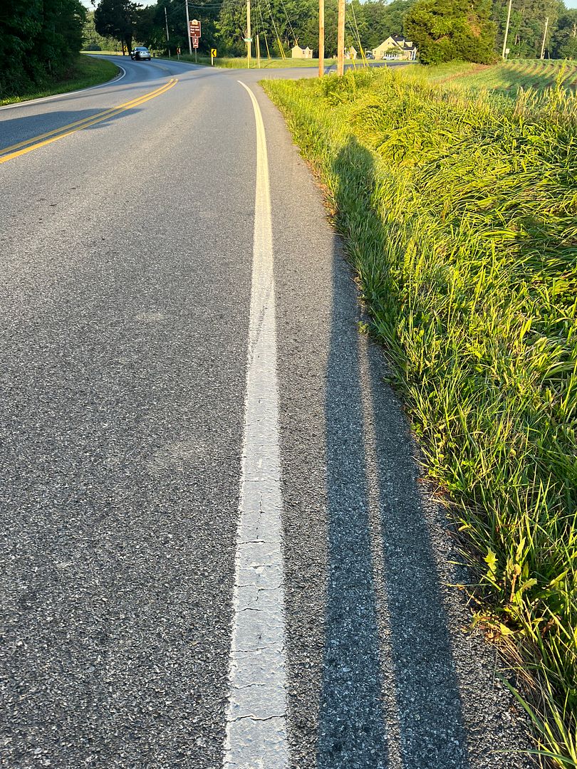
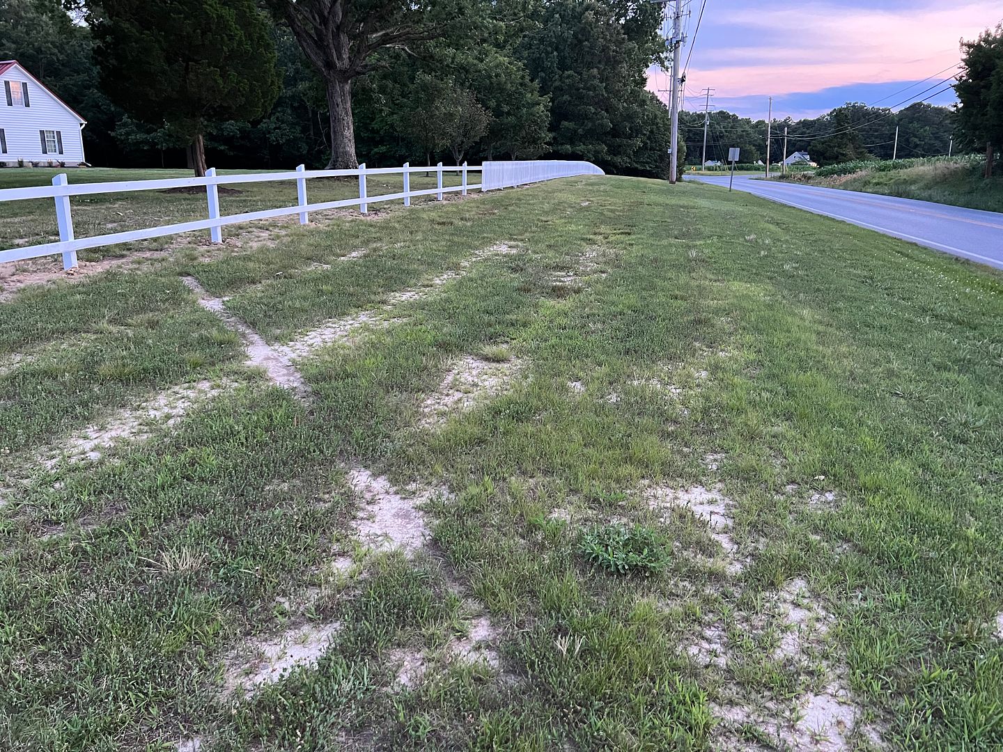
So I've been rather lax on the updates as we've had a distraction here at the shop. Someone had a mishap in returning home on Memorial day (about midnight) from one of the local watering holes. Let's call him "Dale Jr"
Seems he was coming in a bit hot in the final turn where his left tires were out in the grass in the opposite lane..
Which, when combined with over-correction....
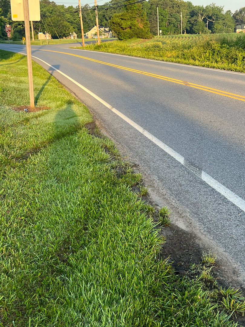
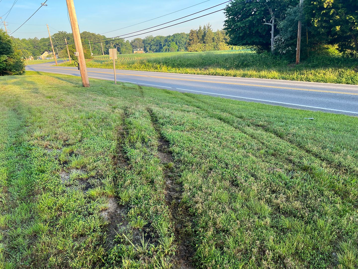
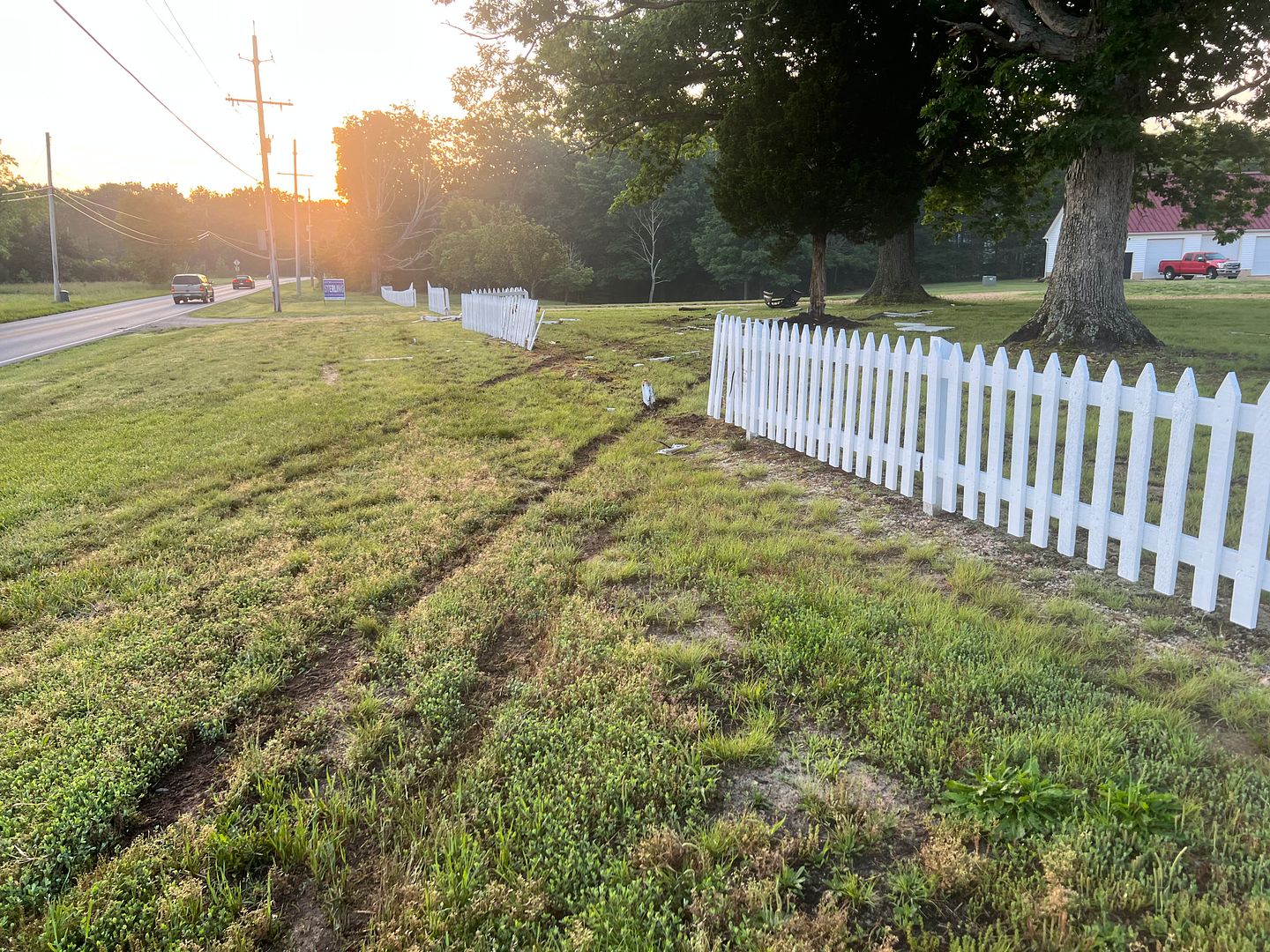
Here, I guess not wanting to go a lap down, he took the nearest path back to the "track", completely ignoring pit road to his right....
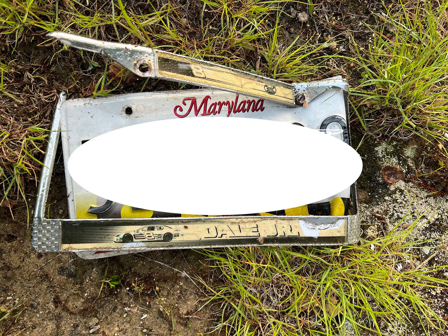
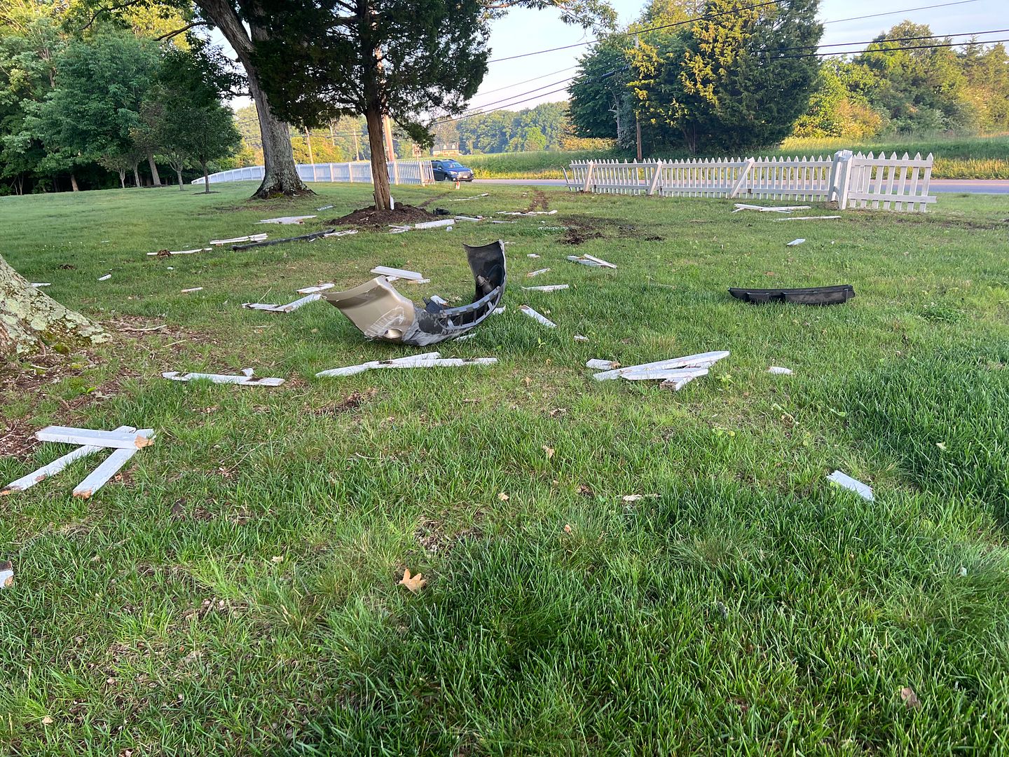
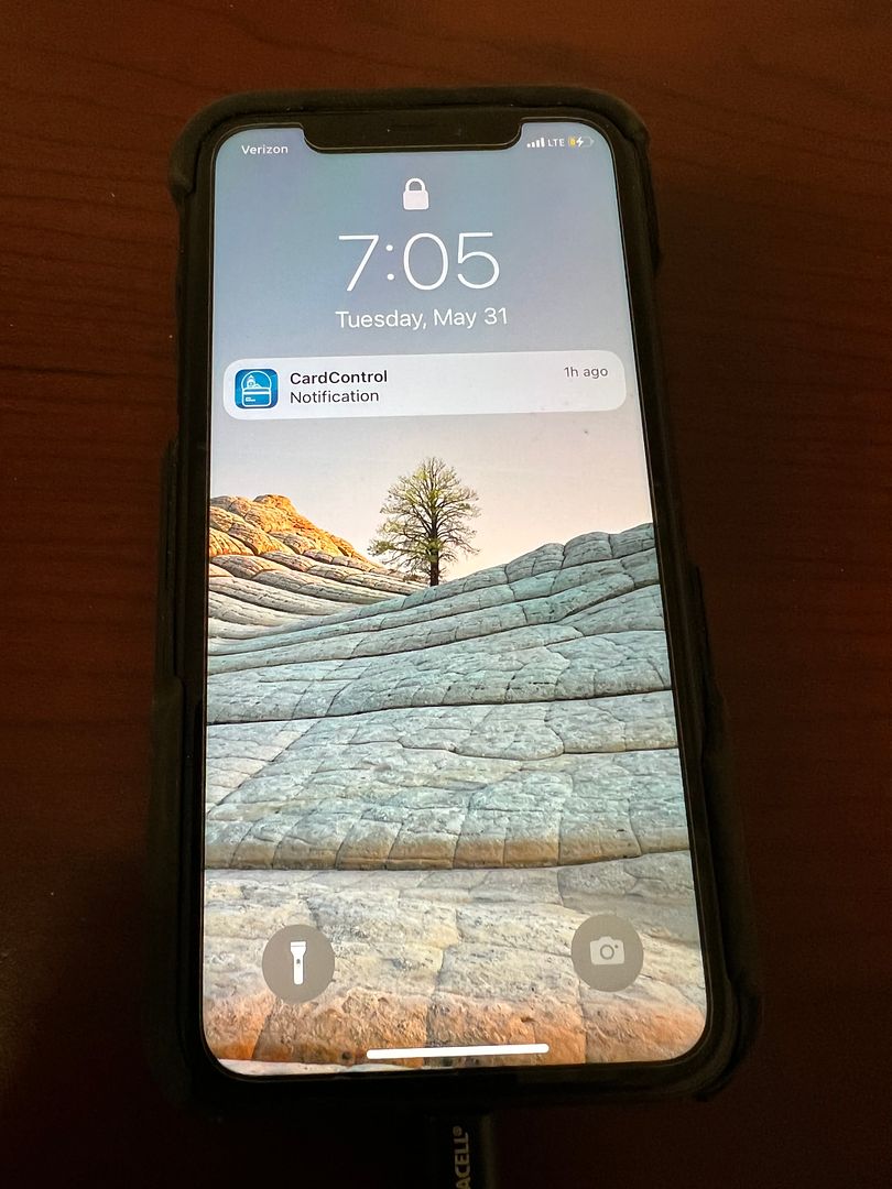
The remnants left behind suggested the drivers window broke out, likely when this gem flew out of the vehicle...
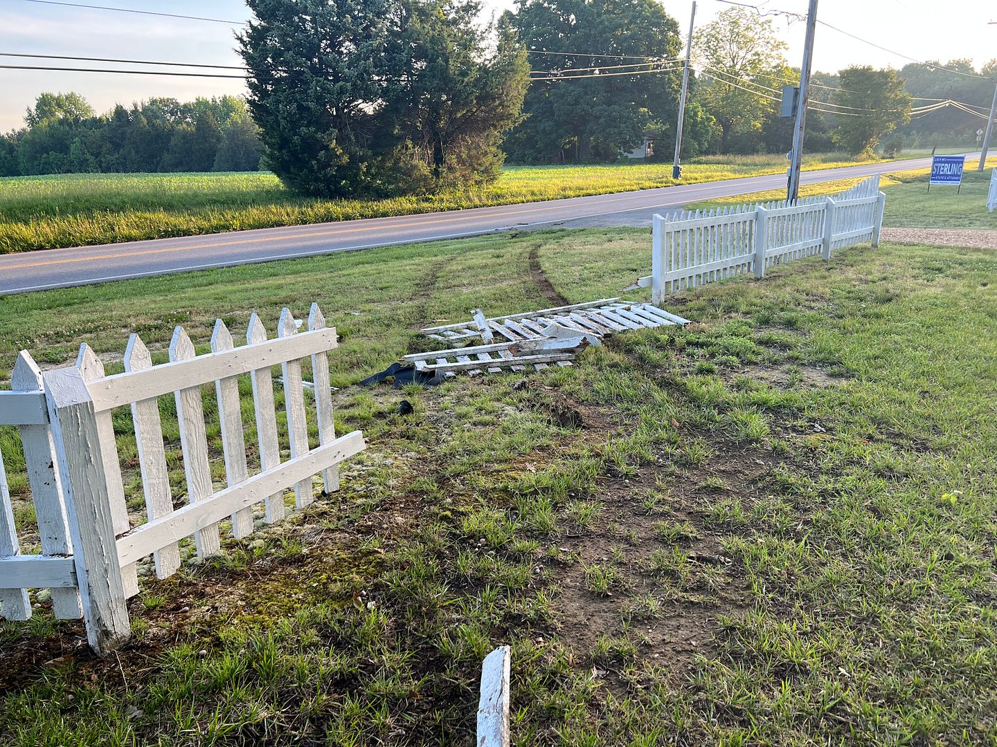
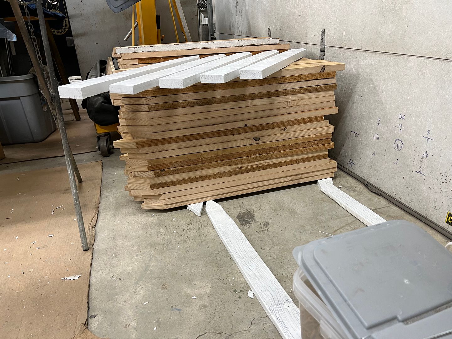
So we've been rebuilding from that the past few weeks in spare time, pre-painting pickets to limit June/July sun exposure.....
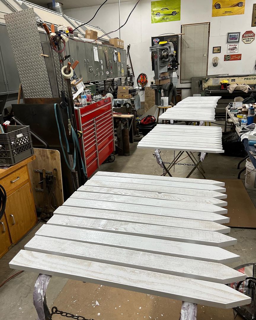
and we finished off here yesterday around noon...
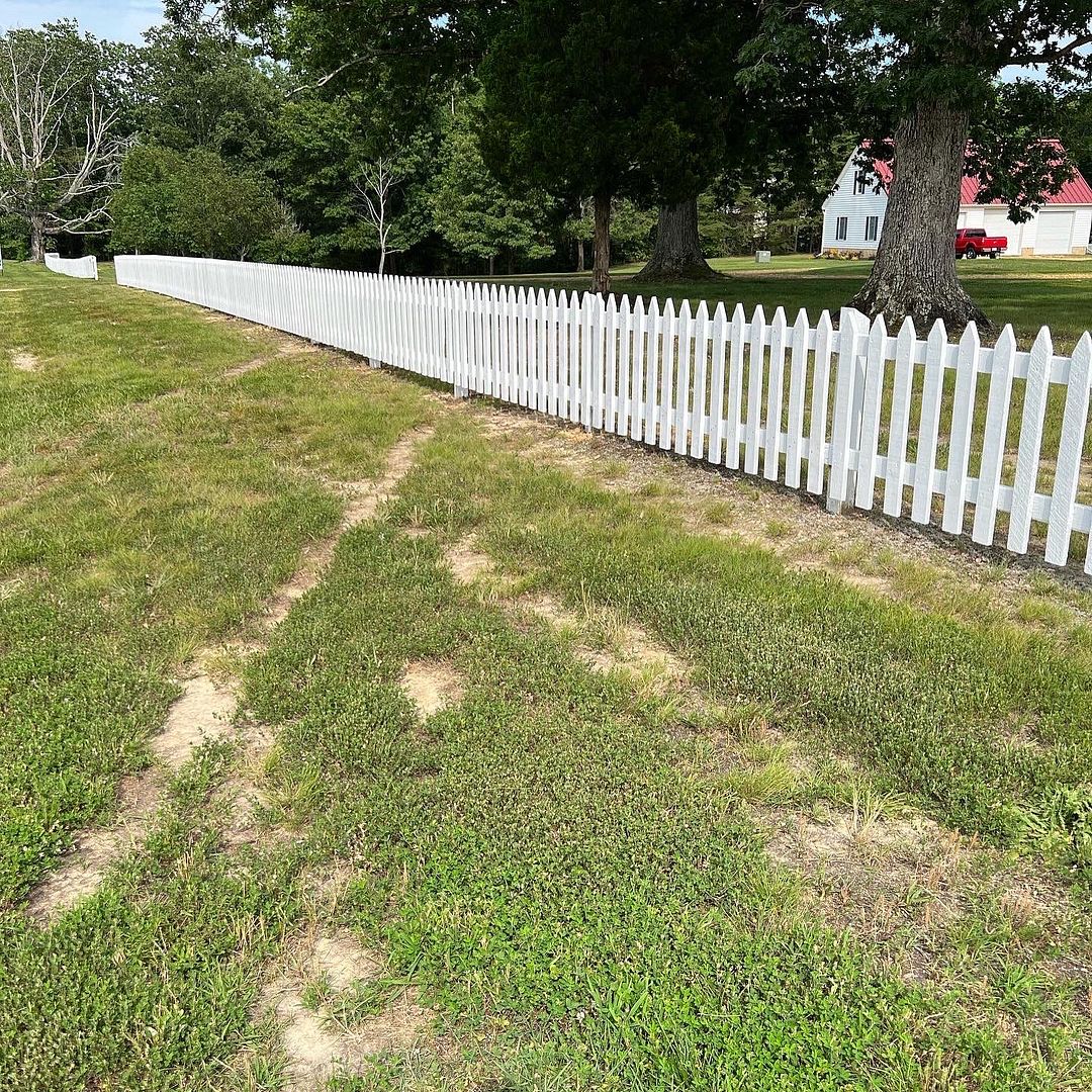
Still have one more coat of paint to apply, but this will hold it until cooler days or the next mishap at the track..
Seems he was coming in a bit hot in the final turn where his left tires were out in the grass in the opposite lane..
Which, when combined with over-correction....
Here, I guess not wanting to go a lap down, he took the nearest path back to the "track", completely ignoring pit road to his right....
The remnants left behind suggested the drivers window broke out, likely when this gem flew out of the vehicle...
So we've been rebuilding from that the past few weeks in spare time, pre-painting pickets to limit June/July sun exposure.....
and we finished off here yesterday around noon...
Still have one more coat of paint to apply, but this will hold it until cooler days or the next mishap at the track..
MJM
Promoted Users
Let's see, what shall I leave the property owner, my driver's license, license plate, or my cell phone.....decisions decisions lol.
Well he'll beat the drunk driving charge, but it's going to cost him a lot of money, seeing as your labor rate is $150 dollars an hour plus material and 20% markup.
Well he'll beat the drunk driving charge, but it's going to cost him a lot of money, seeing as your labor rate is $150 dollars an hour plus material and 20% markup.
Last edited:
MP&C
Member
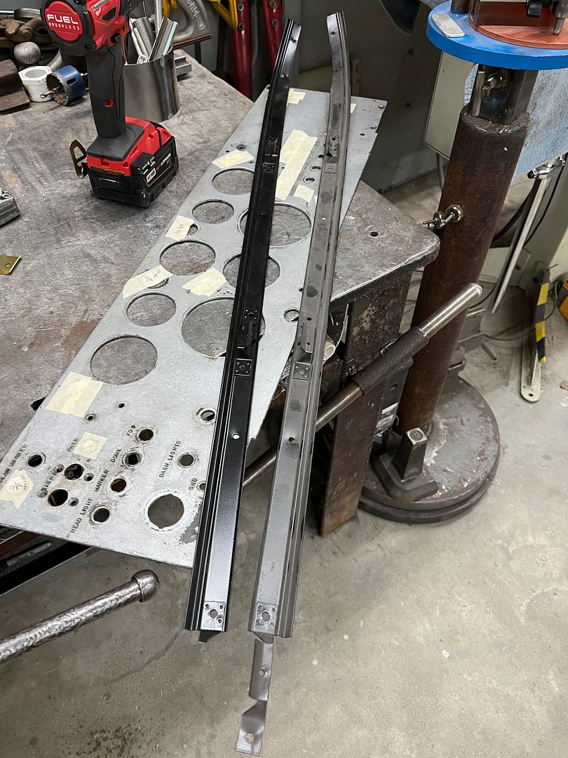
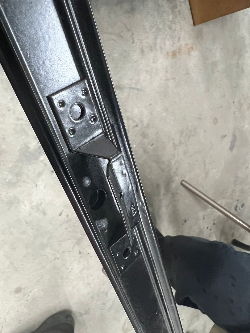
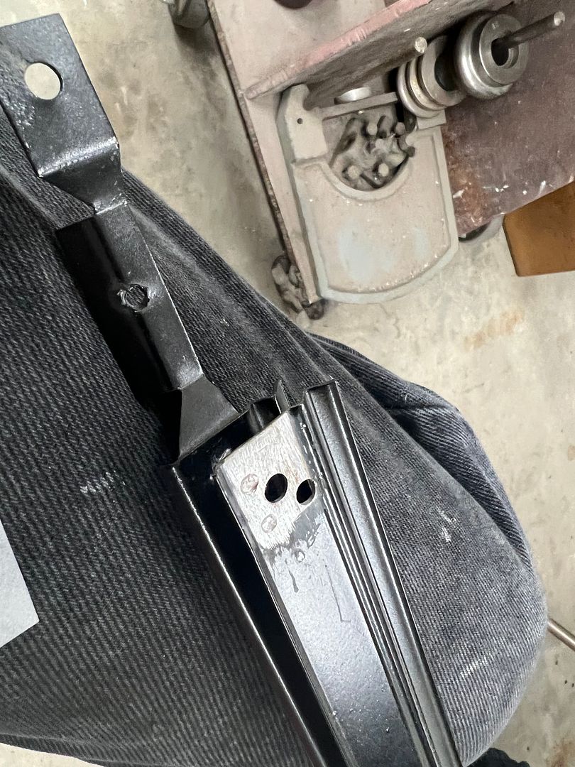
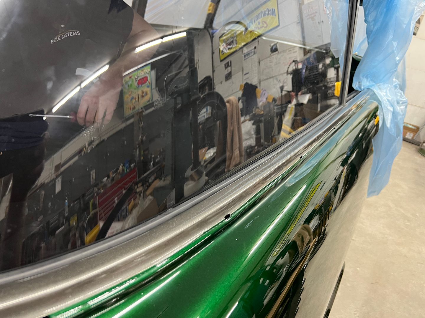
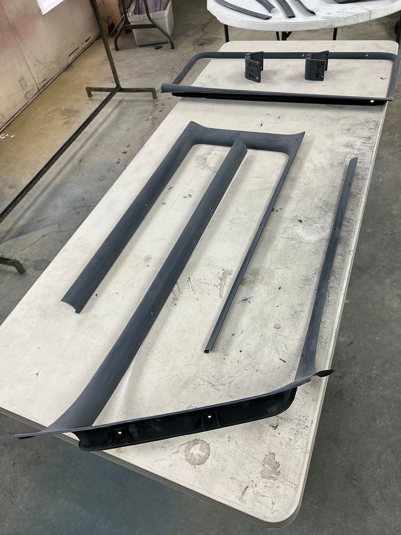
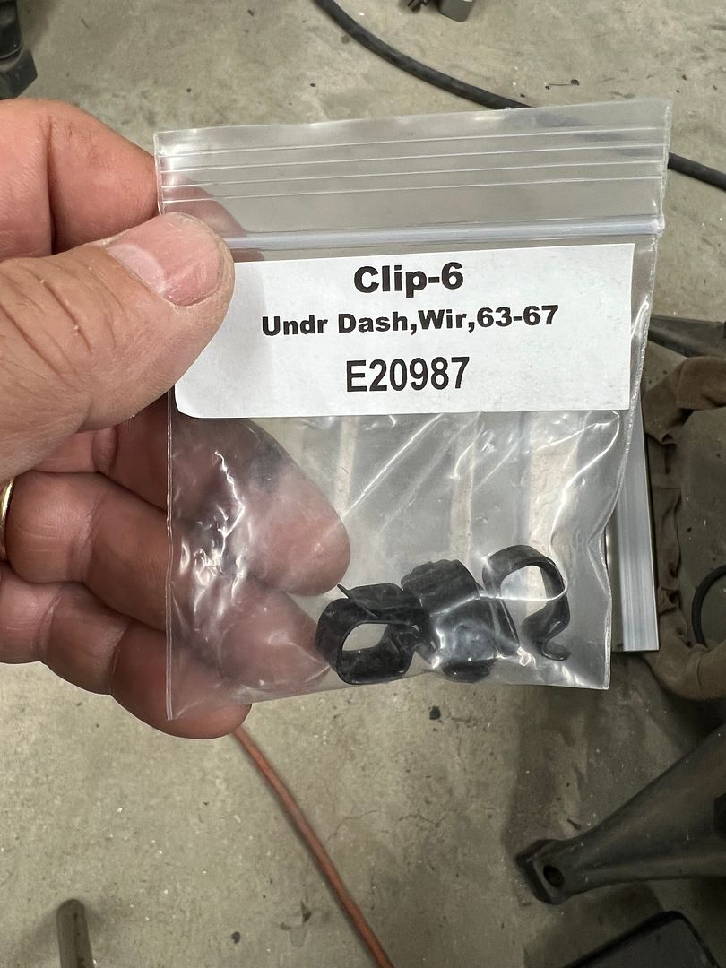
With fence repair duties out of the way we can get back to some progress on the wagon. Finally got the correct clips for the beltline molding...
We had been attempting to polish up some of the stainless trim but always seems to find 67 years worth of scratches difficult to remove. So we opted to give Trizact a try, starting with 1500, then 3000, 5000, and finally 8000.. The edge of the 3000 and up seemed to bear the brunt of the polishing duties, and wore off much sooner than the center. In an effort to get more life out of the trizact pads, we purchased a 5" Dynabrade where we could cut the outer (worn) portion off the pads and continue to use.. The Trizact did well on the stainless, a much easier task at the polishing stage...
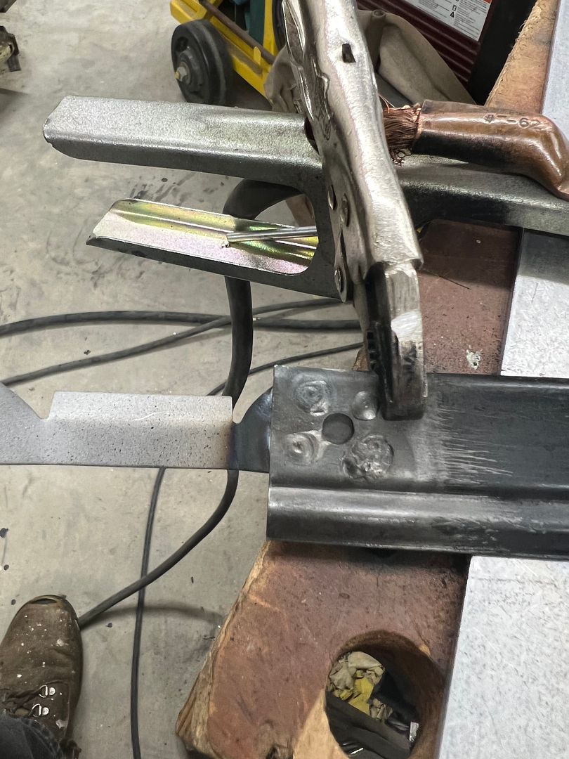
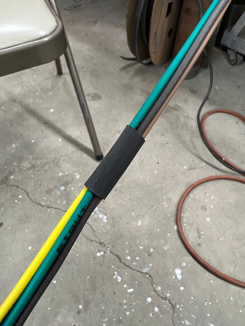
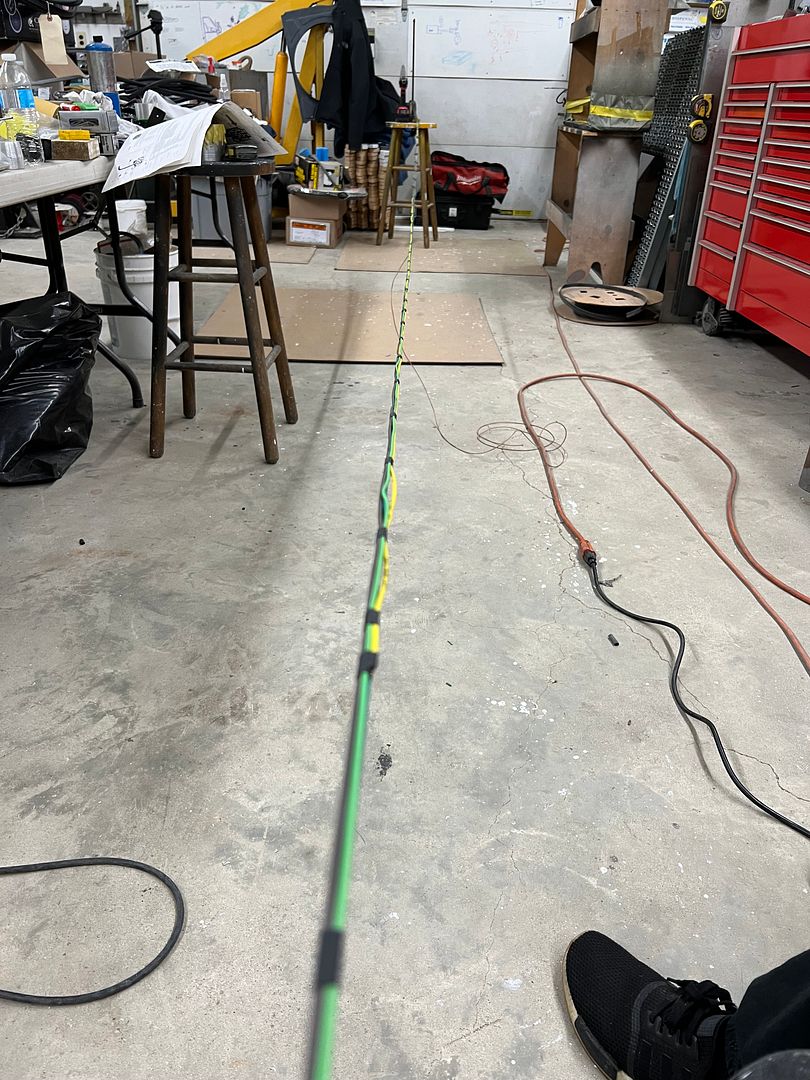
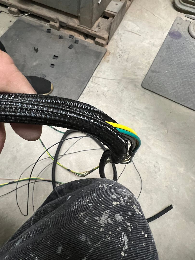
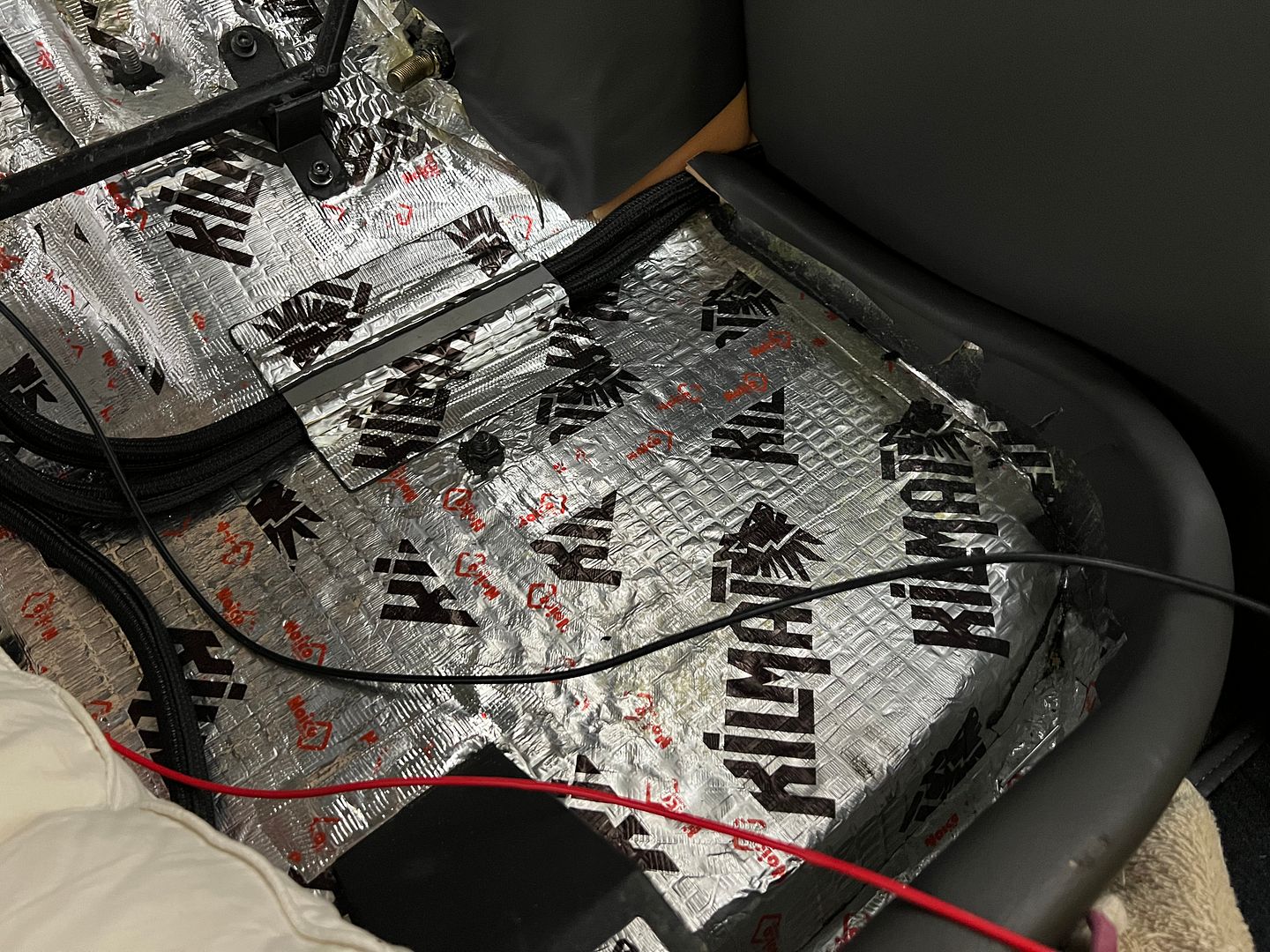
We also have been working on the wiring, and getting it run inside some protective loom. To keep things tidy and knot free, we opted for some heat shrink tubing spaced at regular intervals.. Where I've seen electrical tape used in similar situations, the tape seems to turn into a sticky mess in short order so we'll give this a try. Jared has some re-wiring to do on his 39 coupe so this is good practice (learning curve) for him.. This section is from the fuse box to the rear of the body, the tan wire pulled out is for the fuel sending unit.
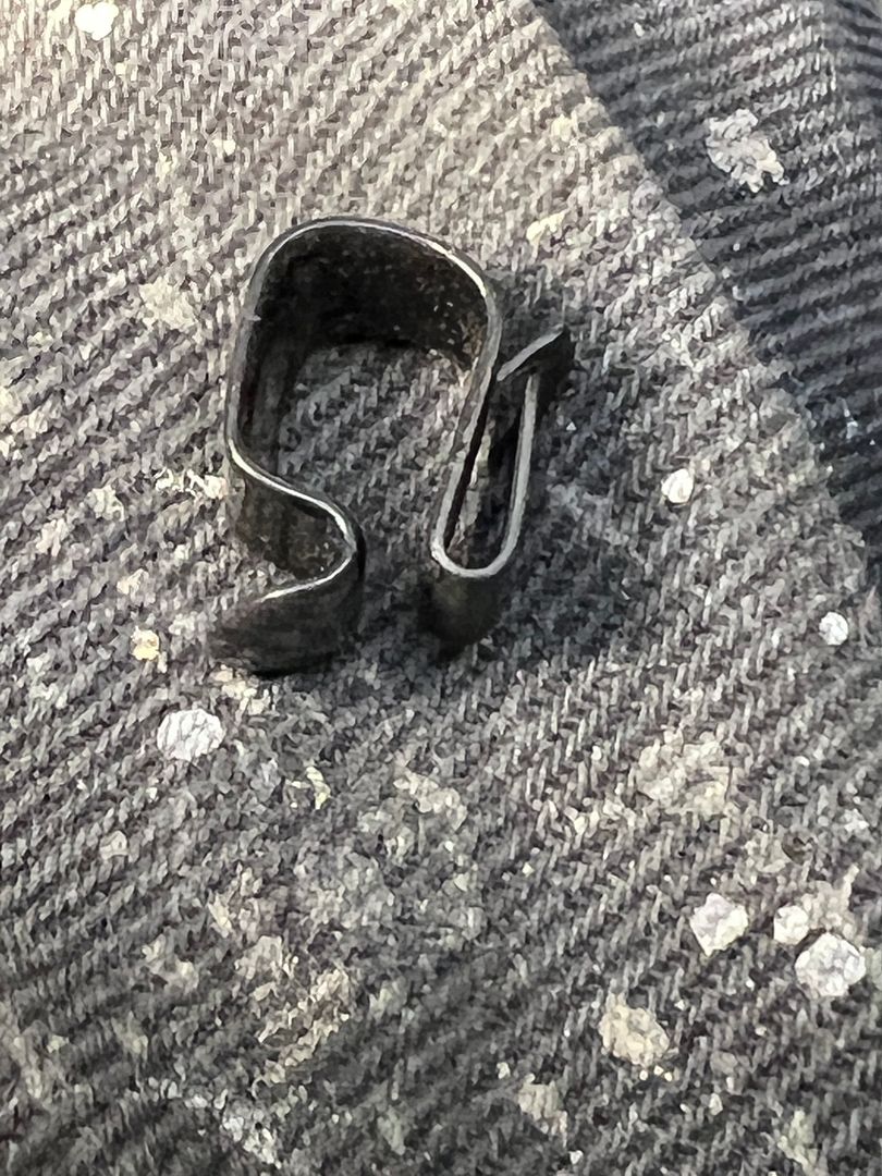
These clips are just about the right size for this harness "portion", we got them to run along the frame rail behind the rear axle, but found use for them in a couple other locations. Corvette part.
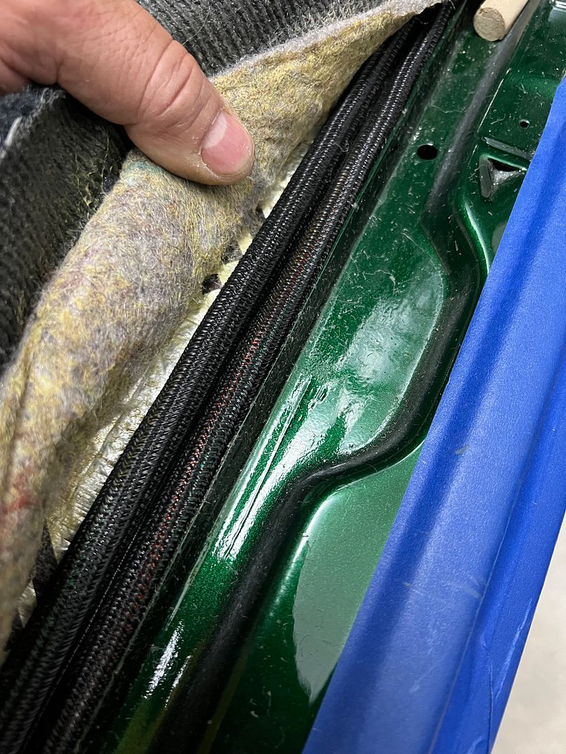
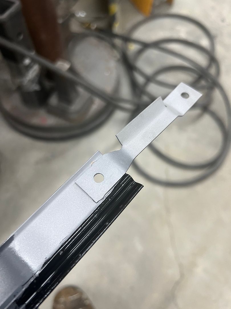
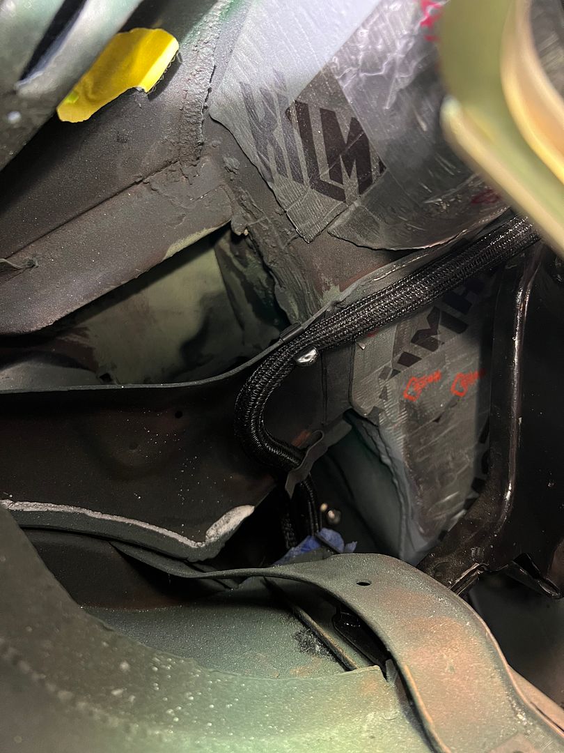
Here Jared made a protective channel where the wire passes under the rear seat frame.
We had been attempting to polish up some of the stainless trim but always seems to find 67 years worth of scratches difficult to remove. So we opted to give Trizact a try, starting with 1500, then 3000, 5000, and finally 8000.. The edge of the 3000 and up seemed to bear the brunt of the polishing duties, and wore off much sooner than the center. In an effort to get more life out of the trizact pads, we purchased a 5" Dynabrade where we could cut the outer (worn) portion off the pads and continue to use.. The Trizact did well on the stainless, a much easier task at the polishing stage...
We also have been working on the wiring, and getting it run inside some protective loom. To keep things tidy and knot free, we opted for some heat shrink tubing spaced at regular intervals.. Where I've seen electrical tape used in similar situations, the tape seems to turn into a sticky mess in short order so we'll give this a try. Jared has some re-wiring to do on his 39 coupe so this is good practice (learning curve) for him.. This section is from the fuse box to the rear of the body, the tan wire pulled out is for the fuel sending unit.
These clips are just about the right size for this harness "portion", we got them to run along the frame rail behind the rear axle, but found use for them in a couple other locations. Corvette part.
Here Jared made a protective channel where the wire passes under the rear seat frame.
MJM
Promoted Users
Clean installation. I concur that electrical tape over time just makes a sticky gooye mess. Your heat shrink idea is a good one.
I installed a Painless wiring harness in my car. The only harness I didn't install was the front headlights / turn signal, so I used the original factory harness. When I had the front of the car apart to move the radiator forward, I made a new wiring harness to replace the weathered original for the front headlights / turn signals. Did I mention I hate wiring, lol. It's an art to make it look good.
Where do you get the black nylon sheathing?