It Followed Me Home...Can I Keep It?

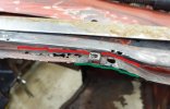
Hey Chris, if it were me I'd bend a full length piece minus the ends. Bend a 1/2-3/4" lip on the back side and then the front 1/8" lip, then form it to match the best you can. Cut at the base of the back (in red) 90 leaving the ends. Taking your formed part trim/grind to match, tuck it in behind the vertical 90 clamp it and plug weld in several locations then weld the seam up. I'm just a novice and I'm sure there's other ways to do it. My .02

TR4 (2).jpg

I have a soft spot for Triumphs, worked in a foreign car shop back in the 70's for a while doing tune ups, brakes and clutch's. GT6's were my favorite, that and the older Lotus.

John
 
One idea would be to form a piece on a shrinker stretcher with too much of a lip but with all the other surfaces the correct size and them saw the lip down to the smaller height needed. I have a pretty decent brake and it does not like small bends.
 
We had a small 4 head rollformer for lips that small that we could adjust the guides for the bends needed other wise anything bigger than 1/4" we'd used a brake. If you have a steel top bench that has a straight edge on it could hammer form it on that. Again just my .02

John
 
Make a paper pattern of the area. Plan on going past the top of the fender (crease or bend area where those holes are)Use a pencil to trace all the info onto the pattern. Place the pattern over the metal and scribe marks onto the metal. Use a ruler or french curve to complete the marks on the metal. Cut out the metal following your paper pattern. Bend the metal to roughly the correct shape. (where it dips). Then use a tipping wheel in the bead roller to get the first bend started. Finish it with the hammer and dolly. Make sure as you do that the correct shape is maintained (the dip area). Then use the tipping wheel to start the second bend, finish with hammer and dolly. Have at least 1/2-3/4" extending so that you can weld it. You want the weld area to be into the outside part. Past those holes. Hope that makes sense.:)
 
Thanks, everyone, for your advice and replies. I decided to give a shot with the shrinker/stretcher, so I bent the 1/8" flange (with it about 1/2" so they could grab something...I'll grind it down later) and went to town. Actually turned out pretty good, but it was tricky getting it to turn back so quickly (upward then downward). I would stretch what I just shrunk, or vice versa since it was so close together. A bit of hammer/dolly work helps. It's not all done, but it's in and it actually fits pretty well. Thanks!!

First bend:
DSC00343.JPG


Had to cheat and put a cut relief in to enable me to turn the corner quickly enough. Will fill that back in with a small patch:
DSC00348.JPG


Tacked in. Goes from about halfway all the way to passenger's side door. Still need to grind down the flange.
DSC00351.JPG


Happy with it.
DSC00350.JPG


Thanks again, everyone.

Chris
 
I'm allowed 4 vehicles + 2 in the shop, besides the wife's and my daily drivers. She understands the disease, but I fear an intervention is coming...
My intervention has come and passed for the most part, as long as I get her projects done on schedule. With any luck I'll have another coming this spring. I think it was Shine that said "it's better to ask for forgiveness than ask for permission"... We'll see!! :)
 
Hi all,
Long time, no update. But, I've continued to slowly get work done. I've got both floors and rockers replaced:
DSC00377.JPG


Along with the battery tray, bottoms of both rear wheel arches and various other patches. Once that stuff was secure, I braced the tub and removed it from the frame:
DSC00487.JPG


I've started stripping the frame and there aren't any real surprises, but I do have a frame patch to do because the water had sat on it where the floor had rusted away. The top is full of pits and they turn the corner and extend about 1/3 of the way down the vertical. Thankfully, it's not in a difficult spot, but it is the frame. I took a wire wheel to it and there are several areas where the pitting is through. Here's a pic:

DSC00493.JPG


The frame is a box section, with the welded seam at the top (in the pic). I think it's about 14-ga, but I need to verify that. My question is how would you recommend I approach the repair? Multiple (maybe two) welded together (weld both sides of union)? Try to manufacture it as a single piece (I don't have heavy-duty metal forming tools, but I might be able to come up with something). The curves of the unwelded corners of the box are pretty rounded so I'd like to do one piece, just not sure I can fabricate it, especially with the curve that happens as the frame moves to the right (in the pic). Two pieces will probably be a hard edge unless I try to round it, but that may be more trouble than it's worth.

Modified pic of my initial thought:
DSC00493_mod.jpg


Any advice / ideas are greatly appreciated. There are no frame patch panels for this area available commercially and I don't have access to a donor frame. The pic isn't clear, but any patch should fit comfortably between that front outrigger and the cross-member that attaches on the left side so I'm not concerned with interference from existing attachments. Thanks!
 
I am not following the "spot welded seam", how about a picture from inside the frame. What is spot welded to what?
 
I try to avoid right angles on structural members.
I also use as large a radius on what would be corners of weld areas.
I was taught Never weld across a structural member.
There are plenty of examples of birds mouth, fish plate, methods of joint design which are more aimed at changing weld orientation to avoid what some would call a notch effect.
It may seem trivial, but having built a replacement tail boom for a Korean War era helicopter, and seeing the method of dropping diameter of the chromoly tube along the length using a v shaped joint at every 90 degrees on the circumference of the external tube was proof of concept.
It’s not always practical or necessary, but it’s still a best practice….my pennies worth on considering
your weld orientation on maintaining structural integrity.
 
I don't see any reason this couldn't be made in one piece. It will need a little pie cut to make it around the corner. My local steel supply has a big press brake the makes rounded corners like your frame has.
 
@wore out welder has given you very good advice.

I would not do what you are proposing in the picture from a welding engineering perspective. Too much unbalanced welding on top side only where the weight compression loading side of the frame (top) leads to too much residual stress on the tension side (bottom) just from welding alone. Warping the frame is a distinct possibility with this localized welding and then creating more tension in the lower part of the frame opposite the welded pieces. Welding a corner as proposed is generally not a good practice on such. Welding sucks in dynamic loading like a car frame bending and unbending in operation driving over bumps, pot holes etc.....that's why you see most with welding in lower stressed areas and with balanced welding amount and sequencing. Try not to put welds across a flange or web whenever possible. It degrades the uniformity of the steel's crystals and creates non-uniform mechanical properties in that area. Fatigue is a problem. In a very cold climate--low temperature fracture toughness is the resulting problem with shock loading. Warm climates--not so problematic.

Best to section out the frame and butt weld in a newly formed replacement with full penetration splice welds. You could plug weld the inserted channel back in rather than spot weld with the same spacing pattern and a 3/8" hole or so. Chris Hamilton or others here with current or previous ICAR certs can better tell you hole sizes or spacing than me. Forming is easy on a press brake or a big enough pan brake with removable "fingers". Any sheet metal shop with a commonly tooled Cincinatti can do that for you. I used to do "fill in work" for hobby people for free provided they were not in a hurry for anything and I had rem material to use up and get rid of or they did not make a pest out of themselves. Many smaller shops will do this if you ask them nicely.

Or-- you can hot bend yourself with a host of more time consuming steps and flame camber the pieces to shape. It's done every day. Find some 12 gauge ASTM A569 or A570 steel sheet and orient the bend lines you will form in the steel sheet piece transverse to the rolling direction. If you have to bend in the direction of the steel's rolling from the mill--for 12 gauge carbon steel not the best practice but like @wore out welder said--use large radius bend dies.
 
The easiest way to make what is pictured in one piece is to use a hammer form. Have some plate cut in the shape of the top side (red line area). Two pieces. One the shape of the piece (red area) needing to be replaced and another to clamp to the piece. The top piece doesn't need to be as accurate. Just slightly smaller than the bottom. The edge of the plate would conform to the bend line. (where the red and yellow lines meet in the pic) If you are on a budget you could use one piece of steel for your bottom (minimum 1/2", thicker would be better) fastened to plywood cut to the same shape. Ideally you would either use plate thick enough to be slightly larger/longer than the bend area. (yellow line area). Or stack plates to get the thickness. If you stack them, drill holes in one and make plug welds to hold them together evenly. Obviously grind the welds flush.

Put the steel on a solid surface. Sandwich the replacement piece to the two pieces of steel. Clamp it very securely. As many clamps as you can fit. Then using a hammer or a wide thick piece of steel (think really thick wide chisel) what would be called a corking tool, start hammering the edge down over the bottom piece. Work around bit by bit. Hammering it gradually down over the bottom piece. Continue until the replacement piece sits tight around the edge against the bottom piece. When finished you will have something that perfectly conforms as long as the hammer form was accurate. You will want to round the edge of the bottom form slightly to give a radius on the bend similar to the piece you are replacing.

Google hammerform and you can find examples of what I tried to describe.
 
Last edited:
Not to usurp, DAT’s input which is sound from my experience, but those questionable welds on factory automobiles were done, with what I had been told by a well respected engineer, a safety factor of 2-3 times the actual required amount of weld. This is done to compensate for lack of QC and or lack of welder skill.
This was part of the reason I chose to include the statement that “ this is not always practical or necessary, but it’s best practice.”
I see the things I was taught not to do , survive years of service without failure.
The information was given in good faith with the absolute goal of being safe and successful.
There are far more educated guys than me that can bring their professional resources to bear on the intricacies of structural design and union.
Respectfully submitted,

I absolutely reserve the right to be wrong….
any welder that never failed an X-ray…hasn’t welded enough yet
 
In this pic are examples of corking tools. (not the hammers:)) These are Delrin, you would want to make yours in steel with similar type rounded off shape. You would use them with your hammer, hammering the tool, to form to the edge/shape.

(Picture used with permission of Peter Tommasini)

image_2056.jpg
 
Back
Top