Patch panel advice needed

Chris_Hamilton

Trying to be the best me, I can be
I'm working on a 71 Chevy C-10 PU. Owner decided that he wanted to fill the marker light holes. So I did the fenders first. Cut out the depressed area of the marker light hole (where the marker light bolts in. Made my patch and welded them in. The first one I used Oxy/Acetylene and it went pretty crazy (warping) as I welded it. No real problem as I just hammered and dollied it until I got it straight again. (Oxy/Acetylene welds are soft) But that took a long time so on the other fender I figured I'd MIG it in because i didn't want to spend as long on it. Well doing it the standard way I've always done, by tacking it, letting it cool, spotting it jumping around, eventually connecting the spots etc. the fender went crazy warping a lot. Had to stop several times grind, hammer then dolly to keep it relatively flat. Got it done and flat but that took a long time as well.
Now got to do the holes in the bed, I don't have near the access that I had with the fenders so I'm tempted to leave the depressed area of the marker light hole there and fit the patch to the opening. I'm scared if I cut the depressed area out then fit my patch the bed is gonna go crazy as well. Will I have an issue with ghosting if I fit the patch to the opening without taking out the depressed part? I wont be overlapping it but fitting the patch to the opening. Truck is going to be black so I'm a little nervous about doing it that way. Thoughts?
 
I think you said before that you have a low pressure small torch, so it sounds like you need to turn the gas down on your torch. Check out the HAZ in this video, it starts during the tack welding.

The guy doing the welding is the welding instructor at Daggar tools. I took a metal shaping class there several years ago, and was very impressed with his use of a torch. He was also one of the welders that did the 59 Imperial speedster. The guy on the fender was the owner of the car, and they built it in this garage in Royal Oak, Mi.

Imperial%20owner_zpsfeywa9xy.jpg


The owner is an artist/designer, I think with one of the big three manufacturers, but he needed help with actually building the car. He had helped several other talented Craftsmen, so they offered all the help he needed, and that took 10,000 hours.

Imperial%20custom_zpscolnxp8b.jpg


The car cut into 46 pieces, removing all the unwanted sections, which also included a three inch section out of middle from front to back. Steve was on of the welders on the project.

Imperial%20modifications_zpsdflw1pp7.jpg
 
Personally I'd rather go through the extra effort of planishing than risk ghosting, especially on a black vehicle. When you did the O/A tacking in place, did you follow Peter's method?


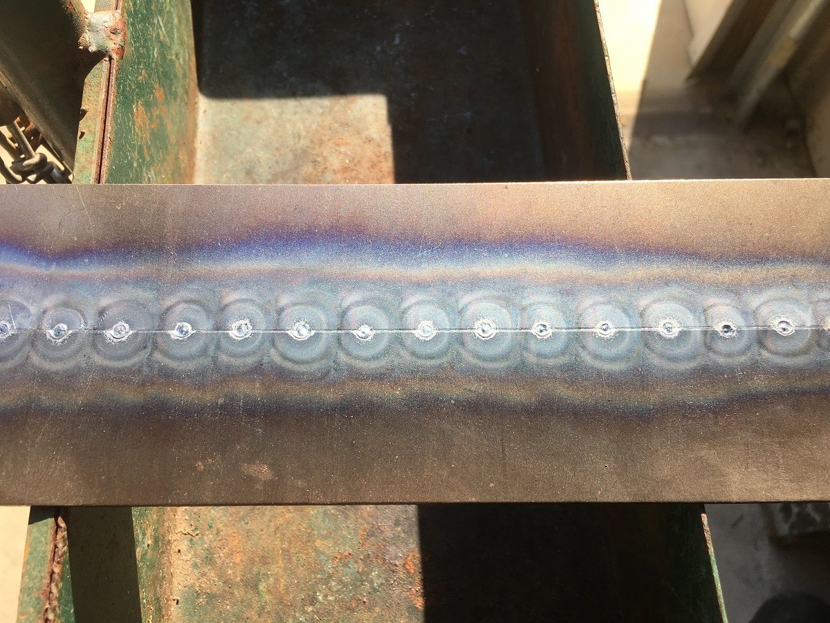
He adds the second (subsequent) tack at the intersection of the previous HAZ line with the joint. When done you'll find that even though its just tacked, you have a nice consistent HAZ width. Here's my attempt at following this method...


IMG_4811.jpg


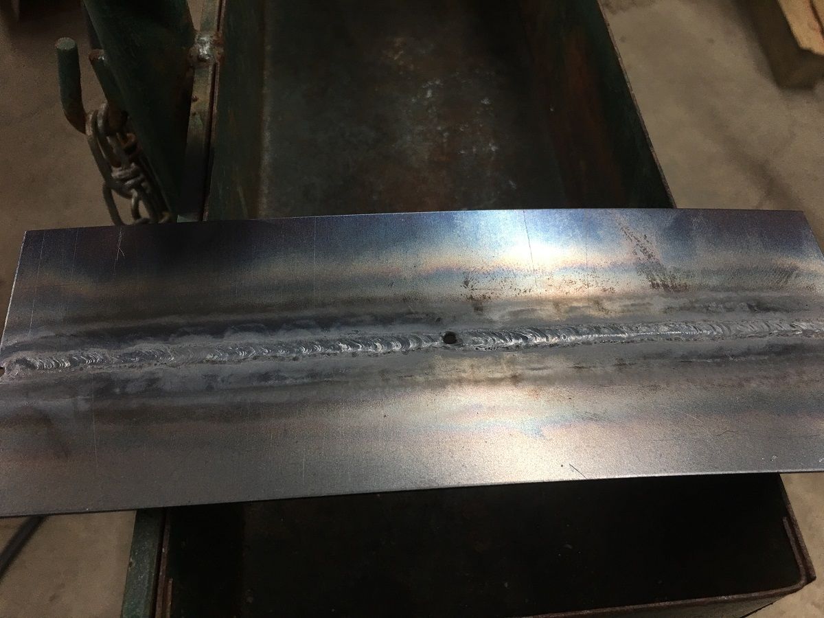
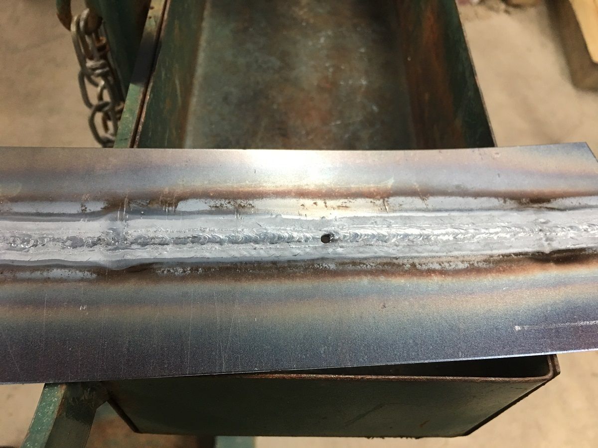
Notice the consistent HAZ width from using this method. And even though I blew a hole in the fusion weld process, the finished shows a nice consistent HAZ as well..

front:

IMG_4815.jpg


rear:


IMG_4816.jpg

IMG_4816.jpg
 
Torch pressure was around 5lbs on both. Used a Meco with the correct tip. Fit wasn't perfect but I have gas welded worse before. HAZ was minimal and even. Especially with the side I did it with the MIG. Extremely small HAZ and it still warped like crazy. Planished it all back by almost exclusively stretching the HAZ on the MIG side. Wish I had taken pictures because I'd never seen one react that way before. Pretty confident that it was not an error in technique or a matter of using better technique to avoid warping as much. Think the amount of heat required in a 6"X 8" patch is the reason. Which is why I migged the 2nd one and even taking a lot of precaution to avoid putting heat into it and it still going bonkers has me worried about doing the true butt-weld on the bed.
 
Reason I am asking is because I have extremely limited access on the bed to get a dolly in there. Only a slapper or a spoon, and if it does anything like the fenders it will be very hard to get it back. My thinking is I can fit it to the edges of the opening, it will butt to them but the depressed area will be underneath. So no overlap more like a T. My worry is like I said that I might have ghosting issues.
 
Reason I am asking is because I have extremely limited access on the bed to get a dolly in there. Only a slapper or a spoon, and if it does anything like the fenders it will be very hard to get it back. My thinking is I can fit it to the edges of the opening, it will butt to them but the depressed area will be underneath. So no overlap more like a T. My worry is like I said that I might have ghosting issues.

Did you planish after the tacking phase as well? I'm sure you did but perhaps that as well as planishing after each length of weld is complete (after cooling) instead of waiting on completion of the entire perimeter weld before planishing. May help to keep thing more in check.


Will I have an issue with ghosting if I fit the patch to the opening without taking out the depressed part? I wont be overlapping it but fitting the patch to the opening. Truck is going to be black so I'm a little nervous about doing it that way

I'd be worried that the little bit of the depressed part will tend to cave in as the outer portion shrinks, and at that point you'd be hard pressed to get the damage out. I think a spoon backing up the gas weld would be more effective in removing any deformation. Do you have an old bedside you could practice on?
 
Nothing to practice with. Robert.
I had to planish after each tack on the side I gas welded. Planished after completing all the tacks. It was moving around like crazy. I really don't think I want to gas it with the limited access on the backside of the bed. Figured with leaving the depressed area and fitting to the edge that I could MIG it in with almost no warping as the depressed area would keep it from warping. Finish it with a skim coat of filler. Main thing is will that ghost? I know Kent White has said you can overlap without issues if it's done a certain way. But I can't remember exactly the way he was talking about.:rolleyes:
Thanks for the help Robert. :)
 
I want to follow this, as this is a pretty common mod. The access at the rear is definitely limited. I think when I've done them before I decided to just live with a significant amount of warpage due to time constraints. I'm sure the amount of filler I used would make a lot of guys here cringe. But it's never been an issue as far as longevity or appearance.
 
Chris, the secret to welding in a patch is to never let it get out of shape. You did right by planishing each tack when you welded the first one. The only area that should need planishing is the HAZ which is where the shrinking occurs. Once the panel is allowed to get out of shape it is very challenging.

I don't envy you trying to weld the bed side where you can't get behind it. When I skinned the door on the '53 I chose the area to place the seam based on my ability to get behind it as well as having some crown in the area.


At this point there was nothing on the door but SPI epoxy. It is time consuming but if you can control the warpage through the whole process, you will be ahead.

BTW, I used my MIG because I was too lazy to fool with the torch. Yes, It is a harder weld but it also will shrink less if you tack it fast and hot.

Good luck with it.

John


Have you tried different wire in your mig? I cannot get my mig to work with shielding gas on the little spot tacks, since I have no pre flow like the tig. But last time out I got some E70C-6M and it was really hard to melt. Guess its made for long vertical and overhead welds. The ER70S melted alot better, but could not get the flow for the tack so it was just porous glob on top. Go back to my standard flux cored E71TS-GS and the power and feed goes way down creating so much less heat.
Since I can only use flux core I pretty much use .035 all the time, and since I cant weld with shielding gas, the .023 has been out of the question, but I am still trying.

What welder are you using? My old ESAB did not like pushing .023 wire and everyone thought I was crazy to use .035 for sheet metal. It takes some playing with the settings, but a higher amperage setting and a real quick trigger pull helped. Then when I switched to ER70S-7 wire in the .035 (ESAB 87HP) I found that the higher Manganese content makes it flow out better for a flatter weld on both sides, and the weld would planish much easier than the S-6 I replaced. Unfortunately the S-7 is only in 44lb spools and .035 from ESAB.

https://www.amazon.com/0-035-ER70S-7-Spoolarc®-Carbon-Welding/dp/B003Y71BE0

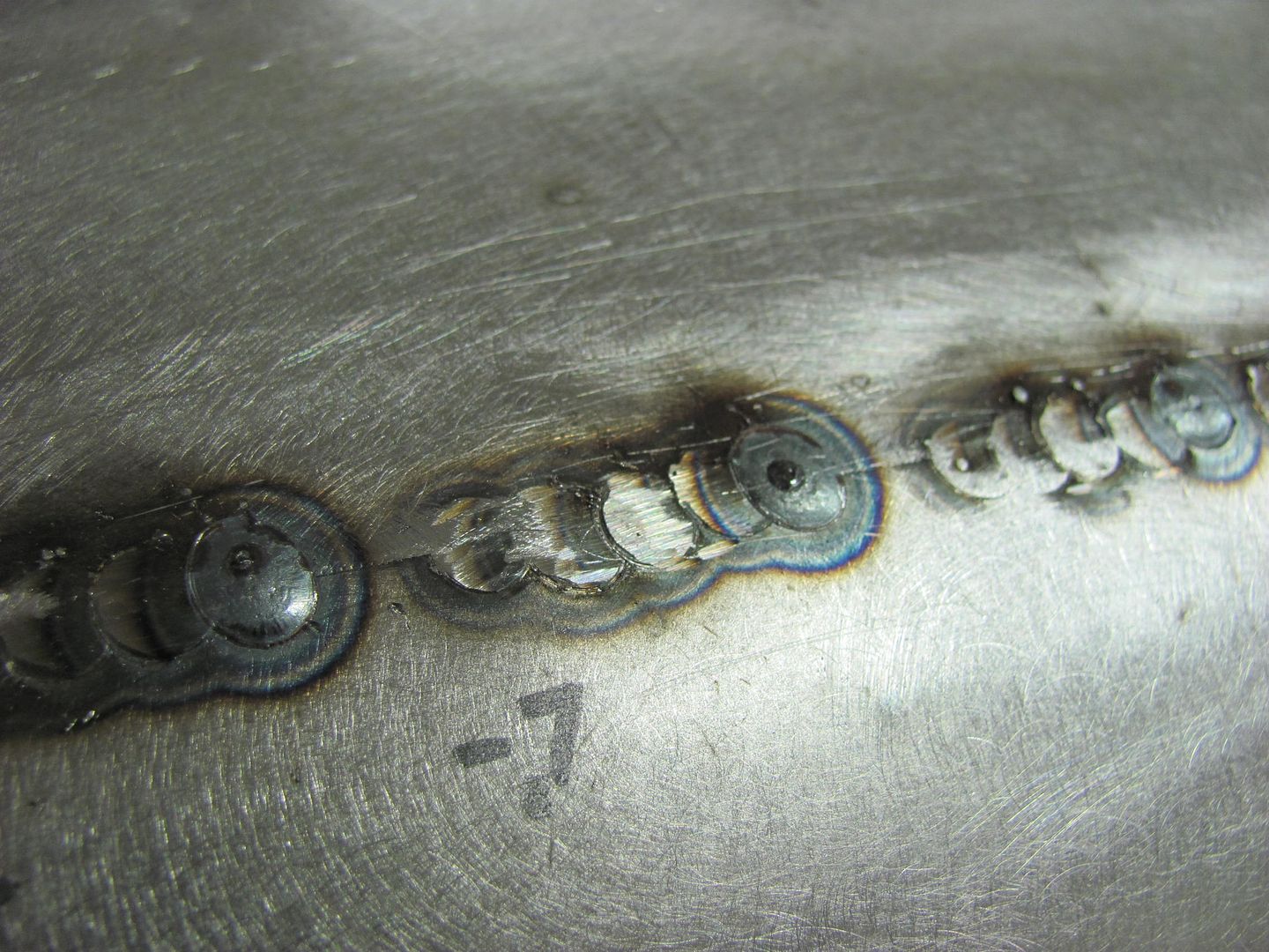
Here's some of the welds I did on wagon roof using the S-7:

Picture671.jpg
 
When you are ready to tack, Run out about a foot of wire on your mig and cut it off. That will purge the line and you can start from there. You should only need to do that when you first start. My 110v Hobart has 4 temp settings and I weld on #3 for 18ga sheet metal. If you look at Roberts picture, you will see how small the HAZ is but also how well the tack is melted in. That is produced by a very hot and quick tack.

John
 
What welder are you using? My old ESAB did not like pushing .023 wire and everyone thought I was crazy to use .035 for sheet metal. It takes some playing with the settings, but a higher amperage setting and a real quick trigger pull helped. Then when I switched to ER70S-7 wire in the .035 (ESAB 87HP) I found that the higher Manganese content makes it flow out better for a flatter weld on both sides, and the weld would planish much easier than the S-6 I replaced. Unfortunately the S-7 is only in 44lb spools and .035 from ESAB.

https://www.amazon.com/0-035-ER70S-7-Spoolarc®-Carbon-Welding/dp/B003Y71BE0

I am using a Hobart 175. No problem welding .250 angle iron and square structural tubing just on the 2 or at most 3 setting. 4 setting will melt .250. Spotting sheet metal closes the gap quite a bit where I need to keep opening up the space with an .035 wheel to keep it from warping. Like on that picture above, you can see the metal already with no gap whatsoever, so when that weld is finished, its probably gonna have to be hammered flat again. To me, thats the bigger deal, once it gets tacked and the two sides meet, continuing to weld is going to start warping a panel.

I almost think there is an advantage to using the flux core considering the middle is basically open? So maybe .035 runs like .030 or smaller since there is technically a core of flux.

I would usually just get Blue Demon from McMaster since I am always ordering stuff, but went to a Kiswell source on ebay and the wire was so much different. The E71T-GS is 57.99 for 2 10 pound spools and the same grade at mcmaster is 102 for one spool.
 
What you are describing is typical when welding sheet metal. The secret, as I mentioned earlier is to control it from the very beginning. Once the weld draws enough for the metal to overlap, there is no way to restore the shape. As you attempt to planish the overlapping area it will be flattened and will grow, making the overlap worse instead of better.

As I said earlier, the weld (and only the weld) needs to be planished. When being planished, it will grow and move the panels back apart where they were to begin with. When doing a long weld like the door skin it is good to start at one end and tack every inch or so moving across the panel. As you do this, watch the opposite end of the gap. It will try to close up with each tack but by careful planishing, you can keep the gap uniform as you work your way accross.

Once you get accross the panel, follow Robert's instructions above, building the tacks on each other until the panel is welded solid.

Here is a picture of the quarter as I was building it. You can see each tack was ground and planished as needed as I worked my way across.

John

 
The question I have is what to do when you have no access to the backside to planish. It seems like every place that needs a patch is on a lower 1/4, lower door corner, rocker, cab corner or some other inaccessible area. No matter what I do I end up with more warpage than I want, though I have gotten a lot better over the last few years, just not where I want to be.
 
Sometimes it is really tuff. I had to skin the bottom of a 41 Packard deck lid once for a friend. I removed the complete deck lid skin, made the repairs and replaced it back on the deck lid frame rather than fight it. I built the quarter panel off the car and was able to weld it back along high crown or rigid areas. I have even opened up access holes to get behind panels.

Sometimes there is just no answer though and you just have to make the best of it.

When The deck lid on the 53 needed repair, I made the skin to replace the bottom 4 inches. Then I removed the inner structure so I could weld the skin and get behind it. Once the skin was welded, I replaced the inner structure, making the pieces and assembling them on the bench. Then welding the assemblies along high crown areas or close to angles. I admit the inner structure needed repair also so it was a bit of a no brainer.

i also admit I spent a good bit of time on the deck lid but the result was worth the added effort.

John


Last edited:
The question I have is what to do when you have no access to the backside to planish. It seems like every place that needs a patch is on a lower 1/4, lower door corner, rocker, cab corner or some other inaccessible area. No matter what I do I end up with more warpage than I want, though I have gotten a lot better over the last few years, just not where I want to be.


I hear people all the time suggesting to only use the bare minimum amount of a patch panel needed to repair the rust. I prefer to look at it another way, For example, most rocker panels have an outward crown that, if we cut out a patch for the front 1/3 only, we are left with a vertical seam. The shrinking that will indeed take place is going to give us a nice valley right at the weld seam. So IMHO, it makes more sense to install a FULL rocker panel, where most are installed with spot (plug) welds at top and bottom flanges. Without using a vertical butt weld seam that you'd need for a partial patch, there is virtually no warpage at all in installing the full panel.

For any other patches, (quarter panel, door corners, etc.), I worry less about using the least amount of patch possible, and more about putting a weld seam where you do have access to planishing. Additionally, a half height quarter patch puts your weld seam in the middle of a low crown area for a guaranteed warpfest. Using a taller quarter (even if not the OEM full height) puts the weld seam up higher where the profile usually has a higher crown, which helps to control the warping a bit better. So if given the choice here, I am using the tallest quarter available and putting the seam: 1) where I have access for planishing 2) in a higher crown area to help control warping 3) near body crease to help control warping (keeping enough distance for dolly placement).

Other body panels would follow same 1-3 considerations in that same order.

For trimming, I try to keep absolute tight joints and if using MIG, set the welder hotter, adjust wire feed faster if it tends to blow holes, and control heat with shorter length of time on the trigger pull. first and foremost, we need to insure full weld penetration, so some practice on scraps of same material thickness and clamped in mid air to simulate what is on the car. (metal welding table is a heat sink) To further explain gap vs no gap, anything welded is going to shrink when the weld cools. If you have a gap, the weld will pull the panels together as it cools, and each subsequent weld will pull it that much closer together. So if your panel had been trimmed correctly, now you have low areas being put in as the panel is moving. If the new patch is trimmed for a tight joint (as I show on roof patch above), then it will still shrink, but you will only need to planish to overcome weld shrinkage, and should not have panels moving together creating low areas. In essence, it will still need planishing as would a gapped joint, but with no gap it should remain more consistent where any planishing required is also consistent. With panels pulling together in a gapped situation, you will have differing planishing requirements based on how much the panel pulled in that particular area. Hope my rambling makes sense.
 
Last edited:
Back
Top