You are using an out of date browser. It may not display this or other websites correctly.
You should upgrade or use an alternative browser.
You should upgrade or use an alternative browser.
Wagon Progress
- Thread starter MP&C
- Start date
MP&C
Member
Thanks!
First off, yes, it's still bolted to the pallet.
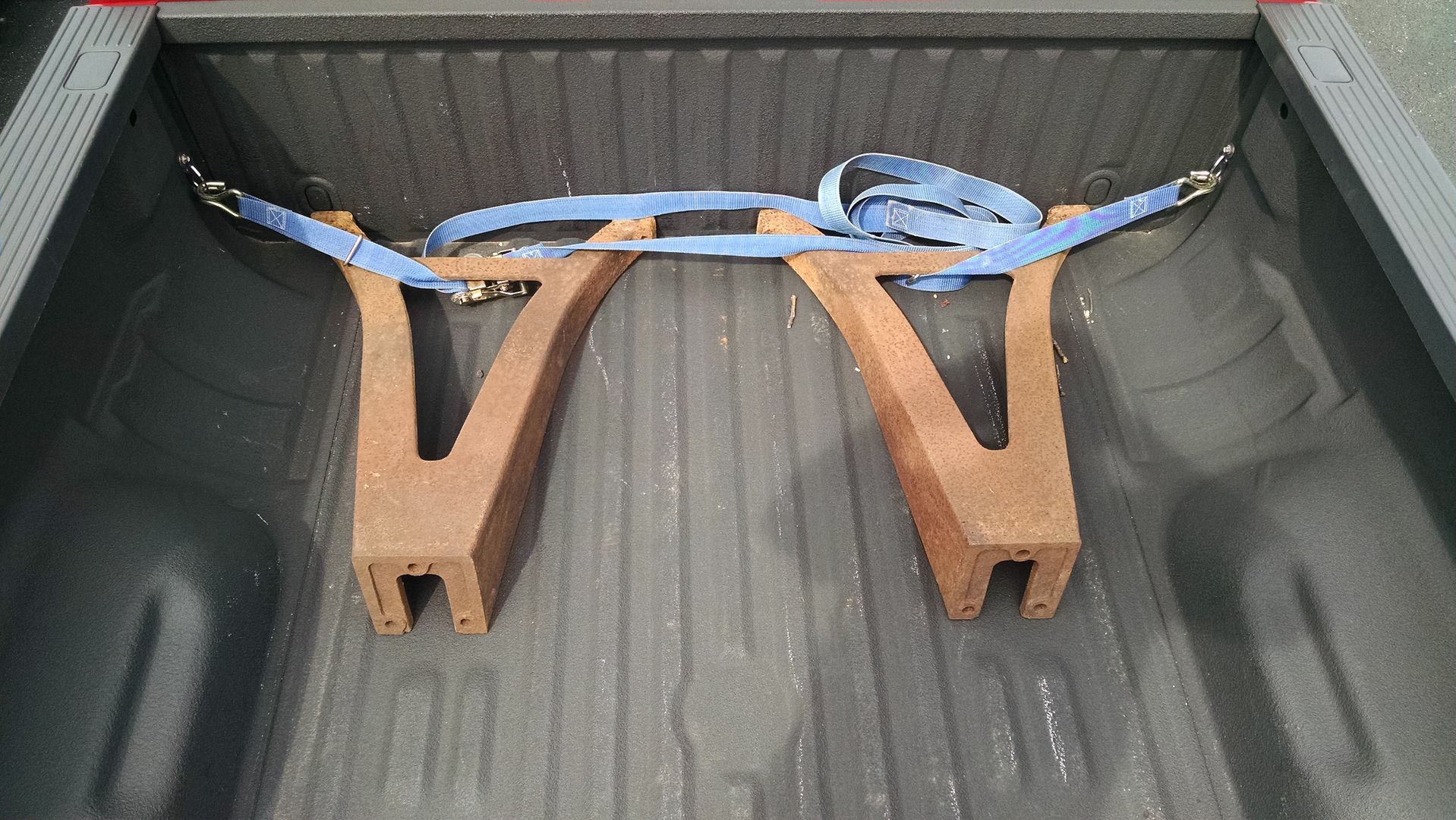
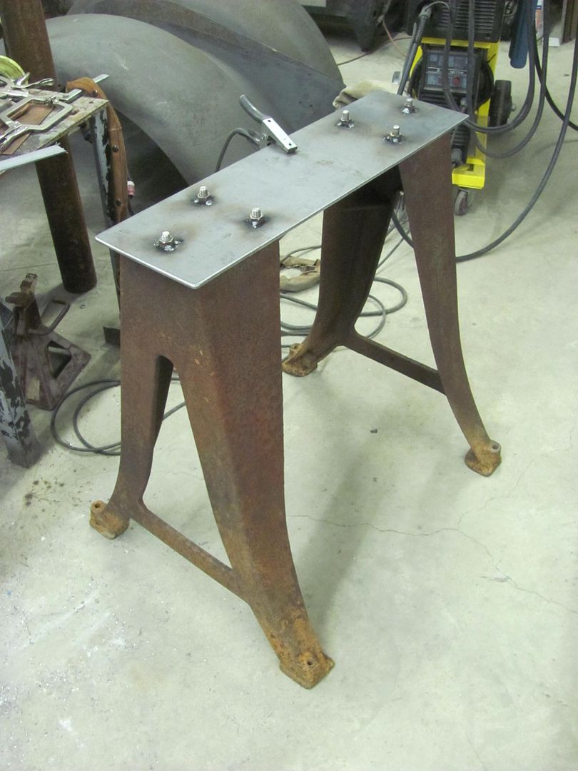
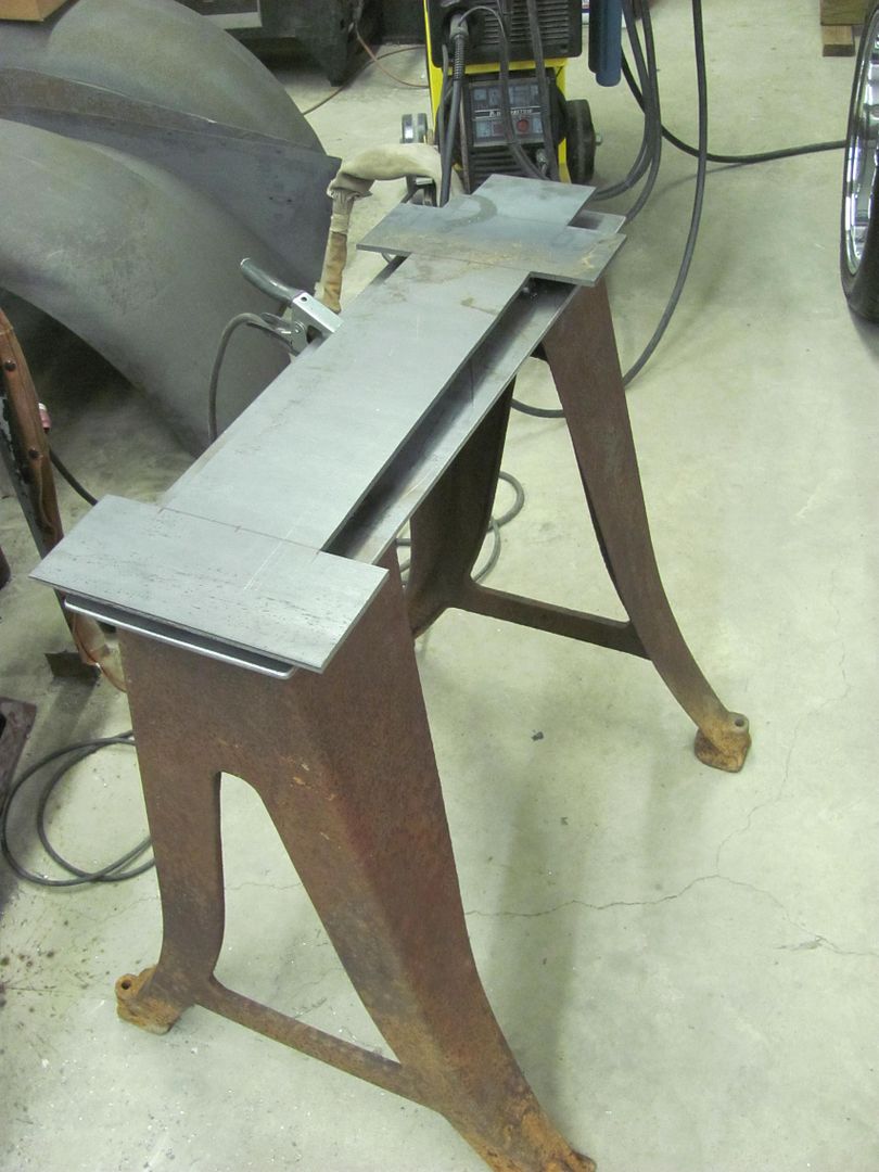
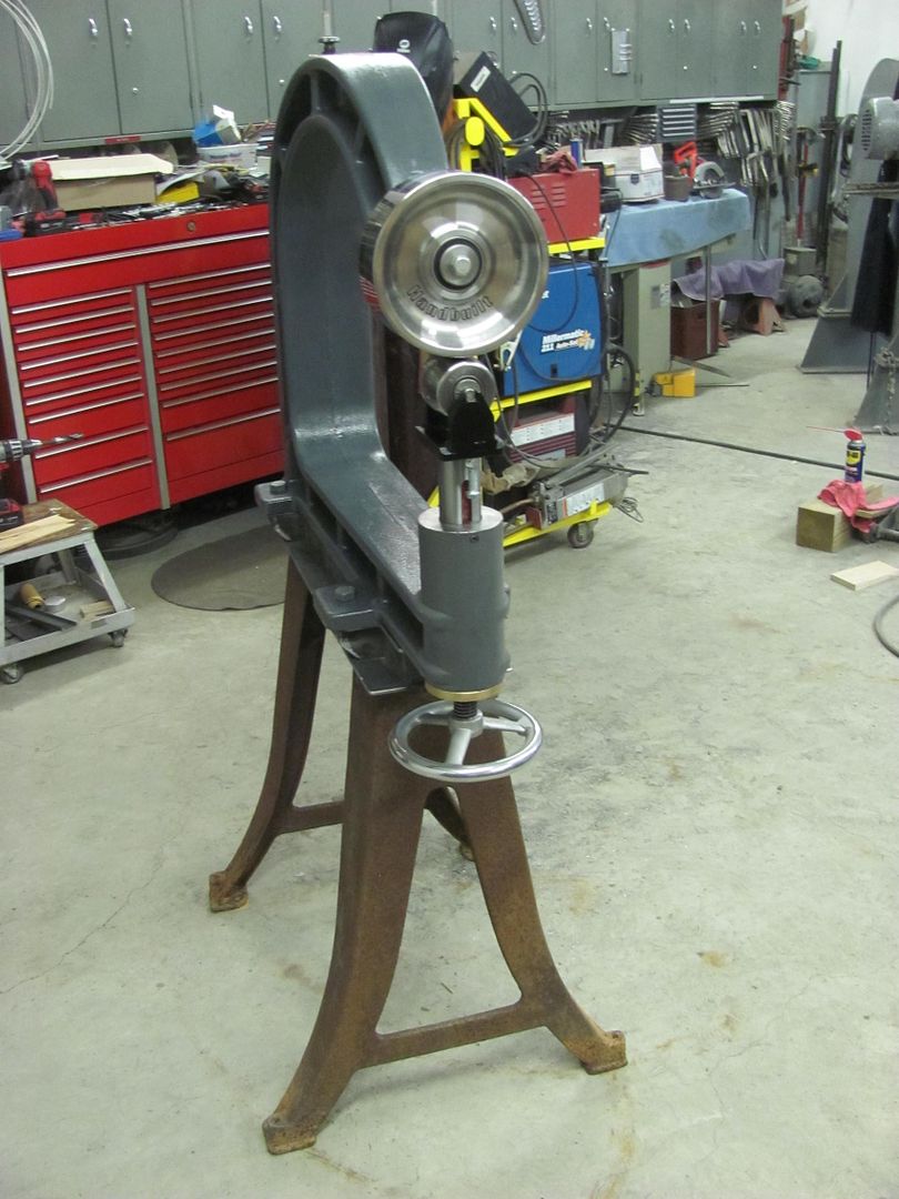
and the more I thought of it I just couldn't bring myself to use fabricated legs. So today was spent driving a 5 hour round trip to pick up some suitable legs..
Here's the lower plate, and by my estimation I need about 4 inches of rise, so it will get some riser plates between the bottom plate and top plate..
More to come..... need to find a nice bright color that will have Peter in sunglasses for his next visit..")
First off, yes, it's still bolted to the pallet.
and the more I thought of it I just couldn't bring myself to use fabricated legs. So today was spent driving a 5 hour round trip to pick up some suitable legs..
Here's the lower plate, and by my estimation I need about 4 inches of rise, so it will get some riser plates between the bottom plate and top plate..
More to come..... need to find a nice bright color that will have Peter in sunglasses for his next visit..
MP&C
Member
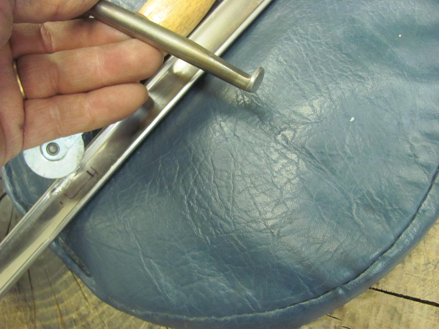
Well I'm back from UK, Kyle is still plugging away on stainless polishing and repairs..
Here's just a few of the implements used. And I must stress, this is not an 18 ga panel, with stainless trim we use light taps for everything.
Here's a piece of Delrin that was cut out and filed to match the bottom side of the door trim to act as a soft "anvil".
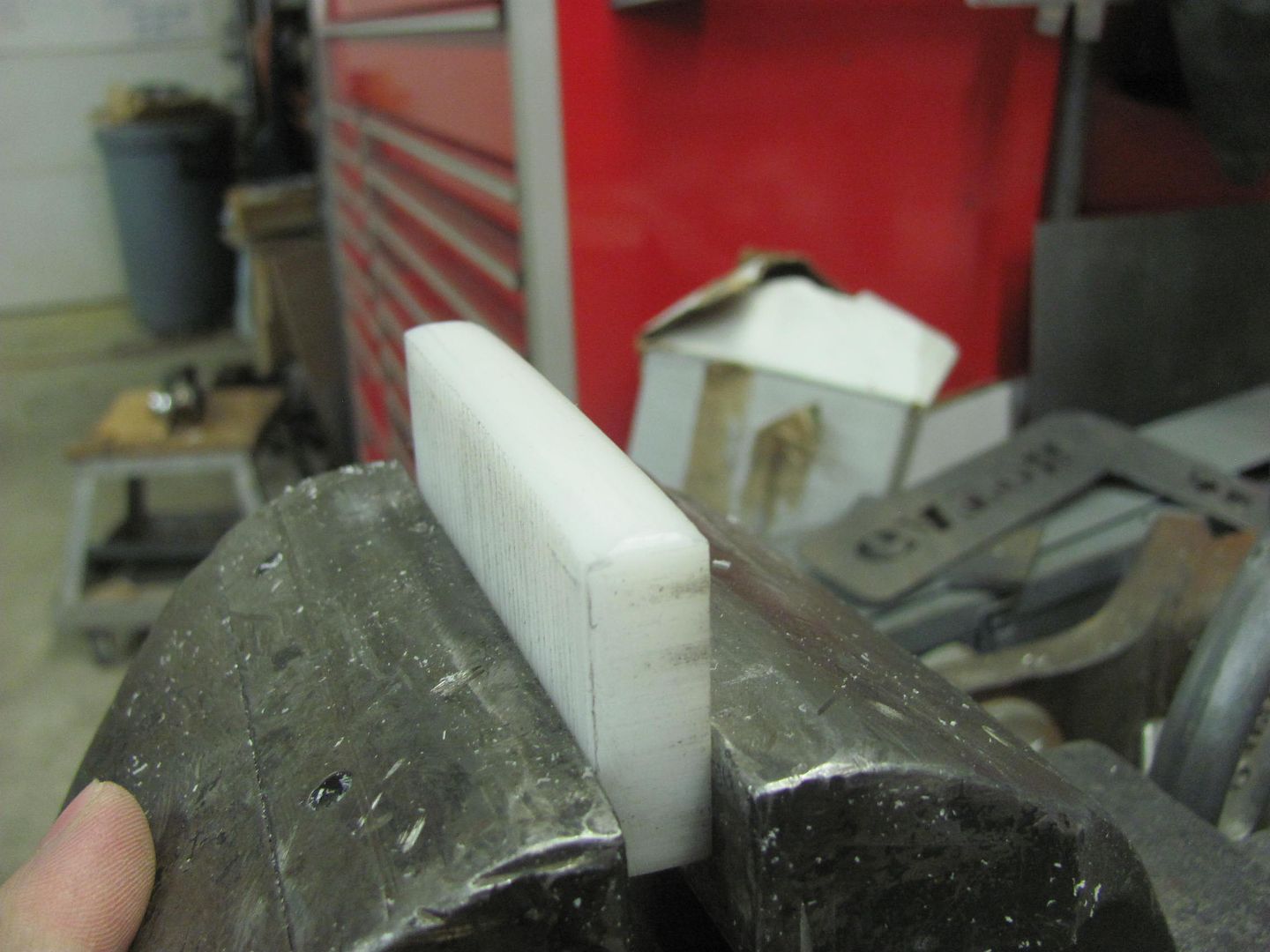
Then a spoon is used to bump.... LIGHTLY
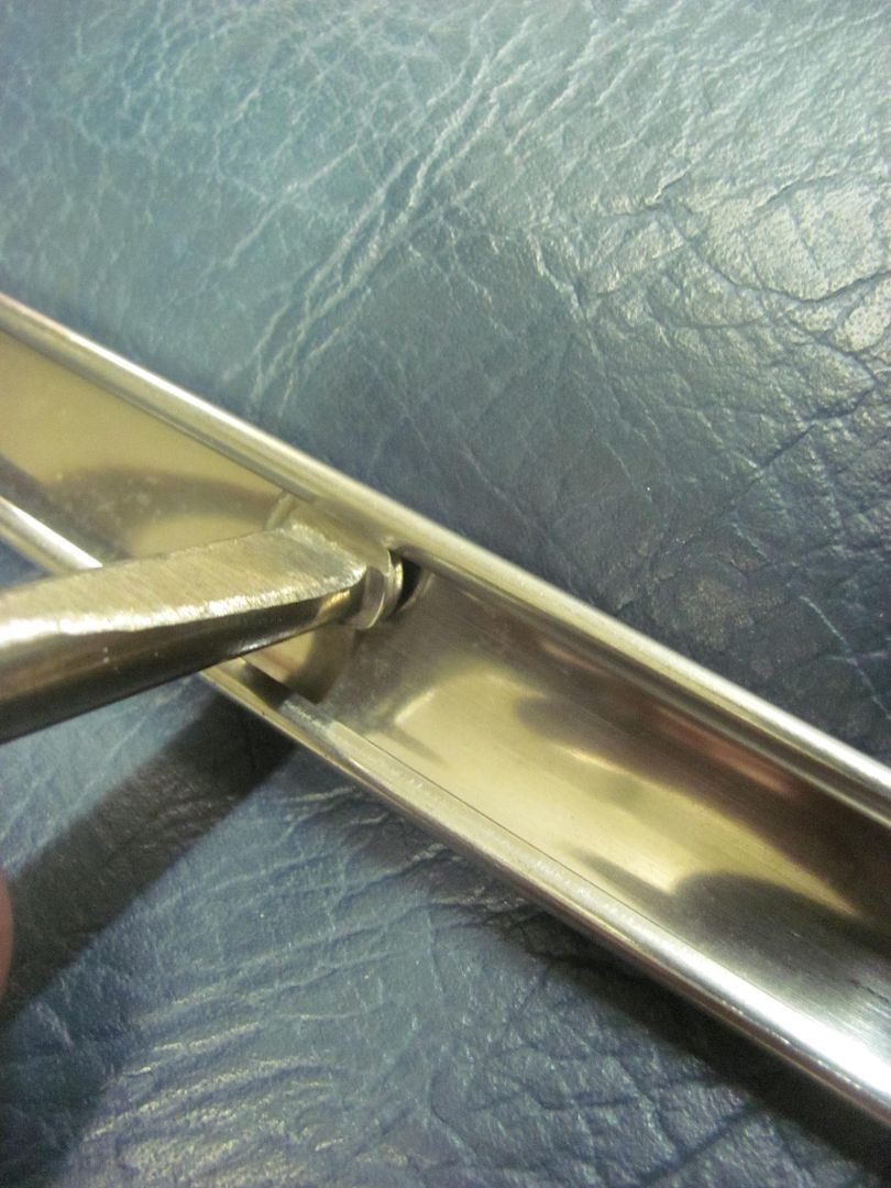
Many ways of bringing up low spots, here are just a couple of the tools used...
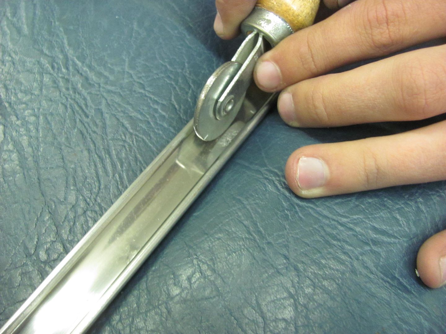
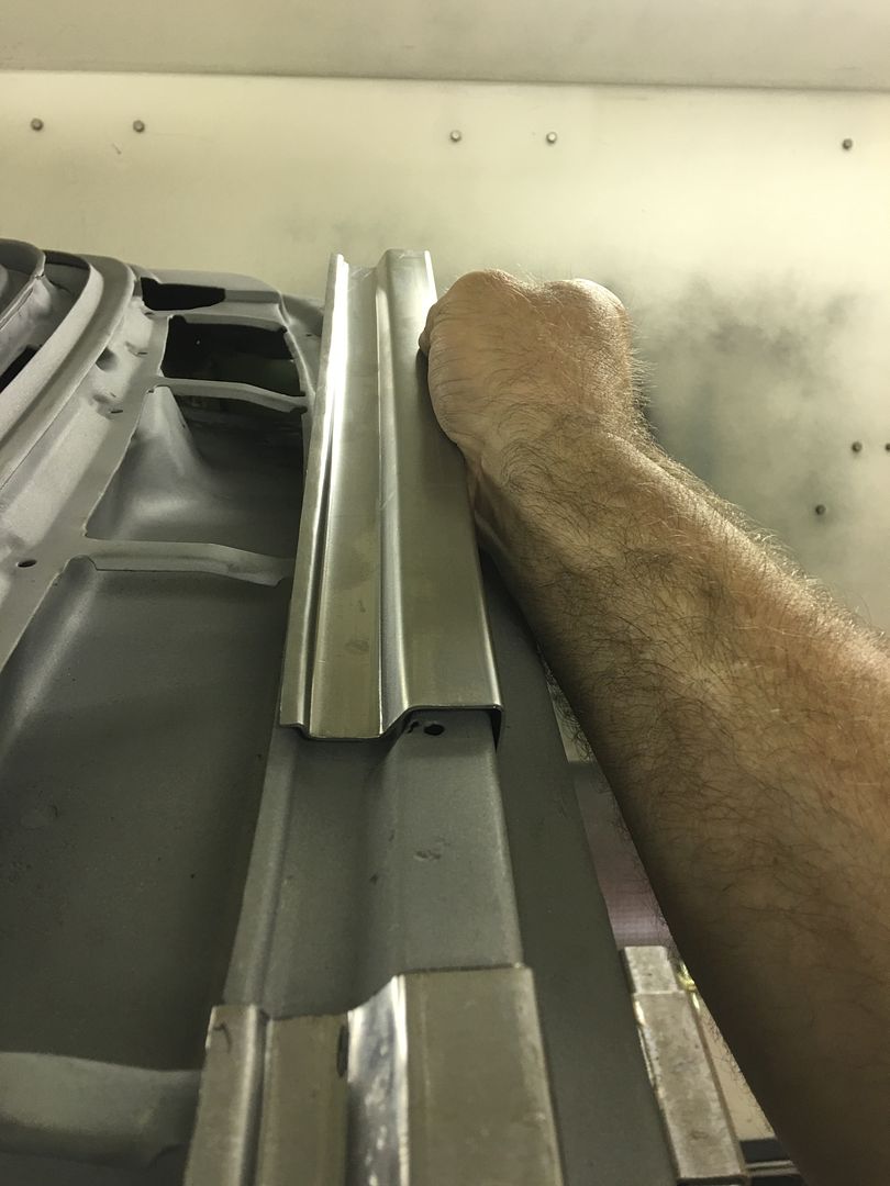
This is a roller tool used for installing the "beading" to hold in screen material. The roller has been flattened from the original version, which had a hollow in the middle. A 3" roloc sander held just right will get the wheel spinning while sanding it flat..
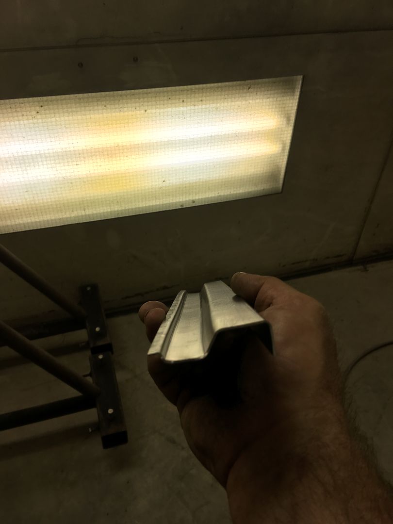
In many cases you'll bump the highs down, roll the lows out, and check your progress using the fluorescent light tube reflections, and repeat. It is not likely this is a one and done process.
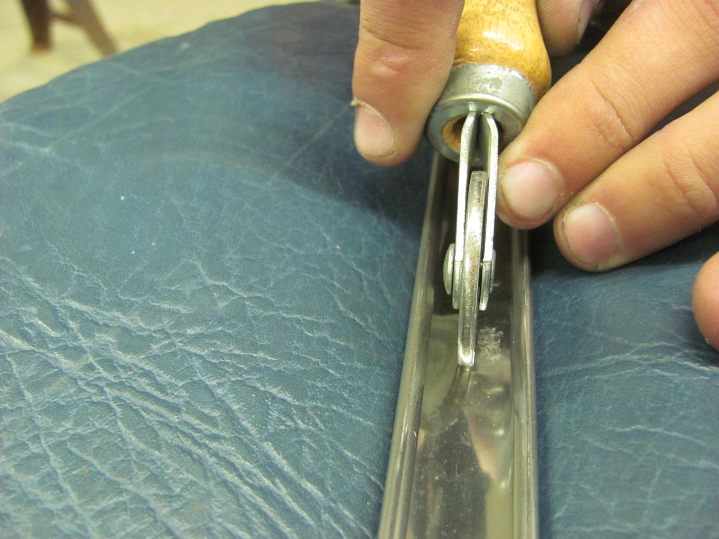
Another tool that can sneak in behind flanges.
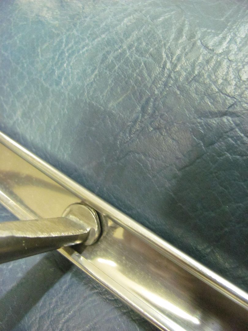
Also used some dry sanding with the durablock, here using 500 then 1200 paper.
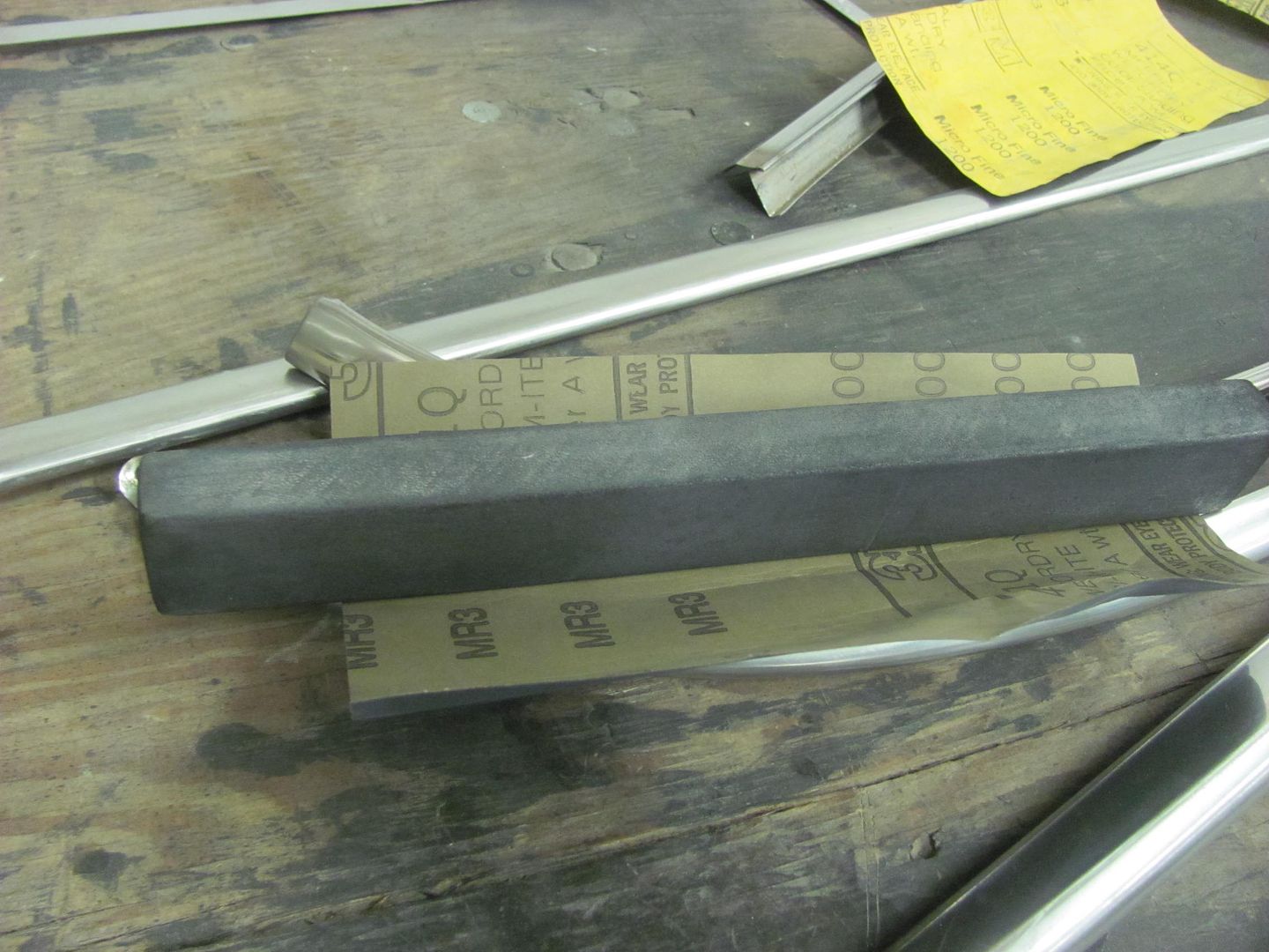
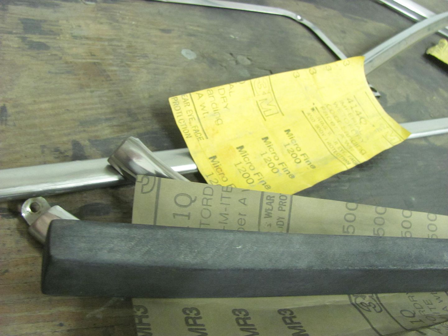
Then followed with the Trizact 1500, then 3000. Then it should be ready for the buffer..
Here's just a few of the implements used. And I must stress, this is not an 18 ga panel, with stainless trim we use light taps for everything.
Here's a piece of Delrin that was cut out and filed to match the bottom side of the door trim to act as a soft "anvil".
Then a spoon is used to bump.... LIGHTLY
Many ways of bringing up low spots, here are just a couple of the tools used...
This is a roller tool used for installing the "beading" to hold in screen material. The roller has been flattened from the original version, which had a hollow in the middle. A 3" roloc sander held just right will get the wheel spinning while sanding it flat..
In many cases you'll bump the highs down, roll the lows out, and check your progress using the fluorescent light tube reflections, and repeat. It is not likely this is a one and done process.
Another tool that can sneak in behind flanges.
Also used some dry sanding with the durablock, here using 500 then 1200 paper.
Then followed with the Trizact 1500, then 3000. Then it should be ready for the buffer..
MP&C
Member
Sorry for the hiatus, the day job had me travelling, two weeks in UK and two weeks in HI. Got back this past Sunday.
Tuesday afternoon we loaded up the wagon and dropped it off for media blasting.. should pick it up this weekend.
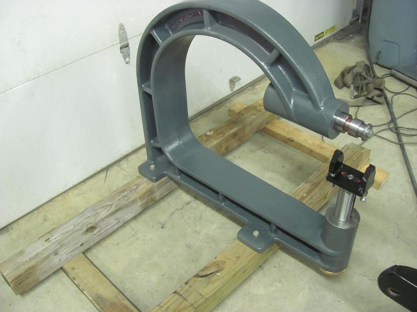
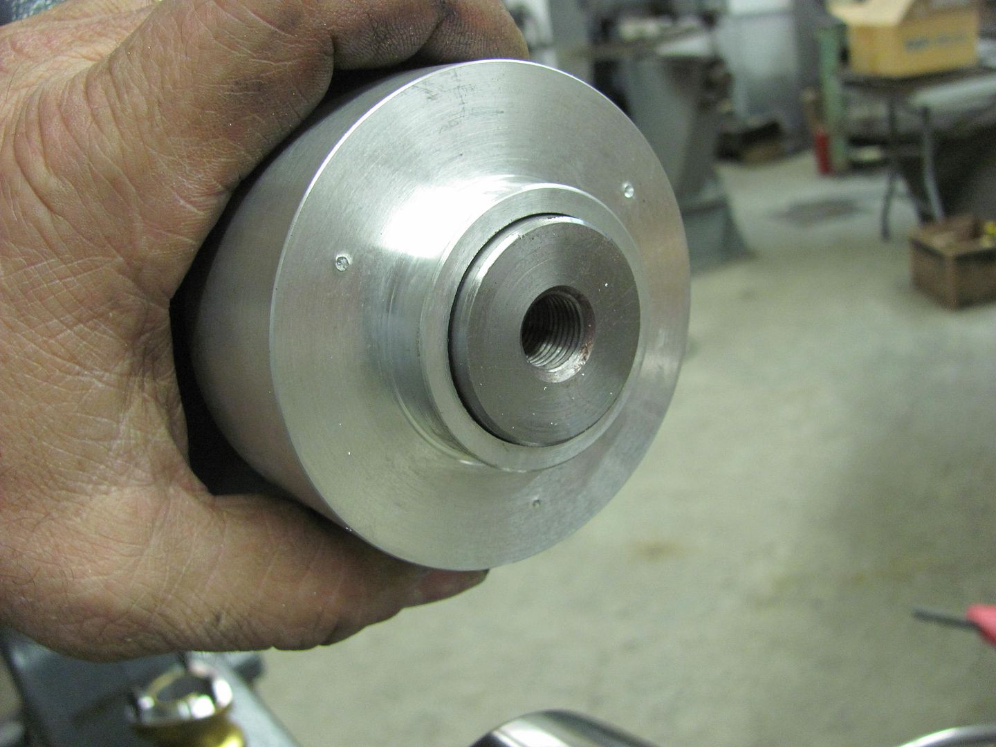
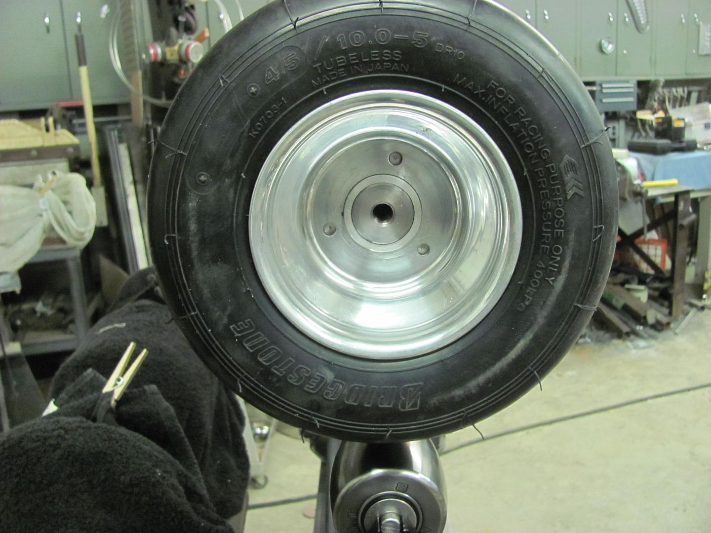
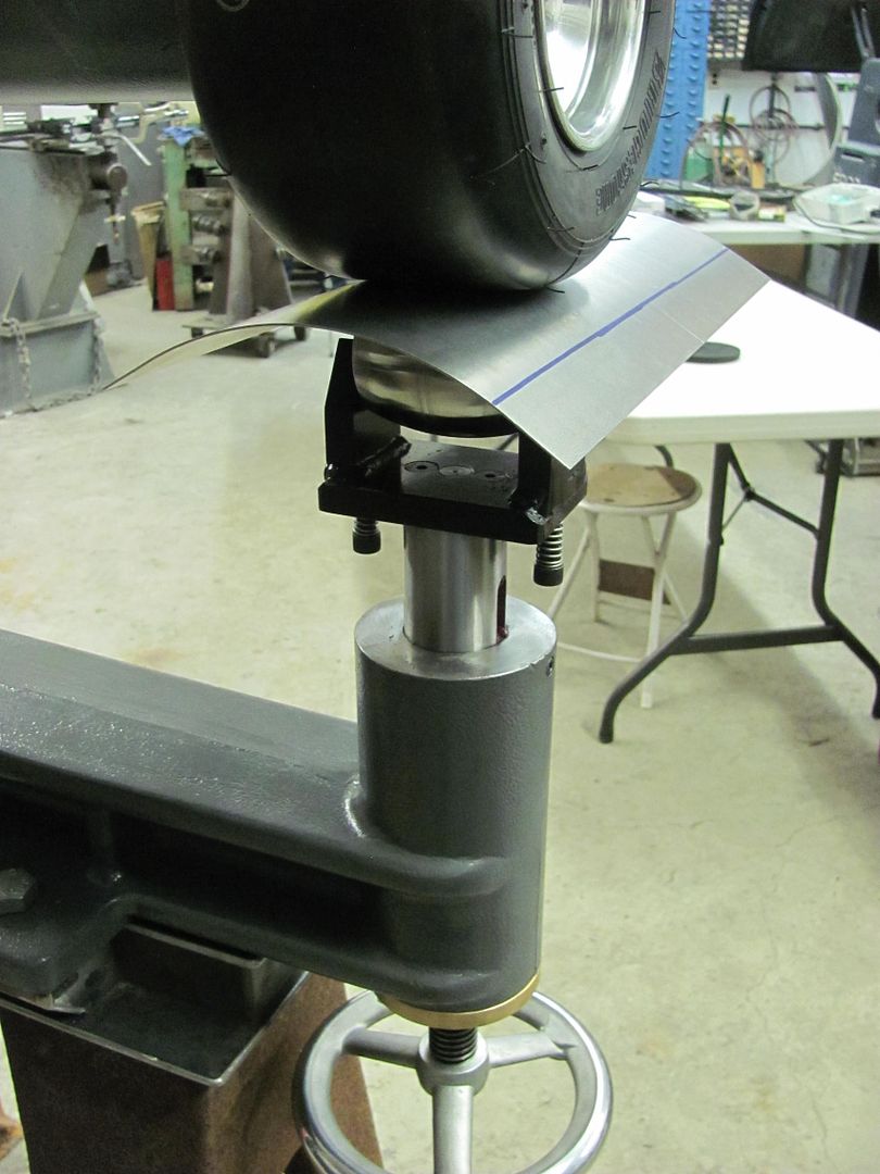
Tonight I worked on getting the Go Kart Slick hub fabricated for the wheeling machine..
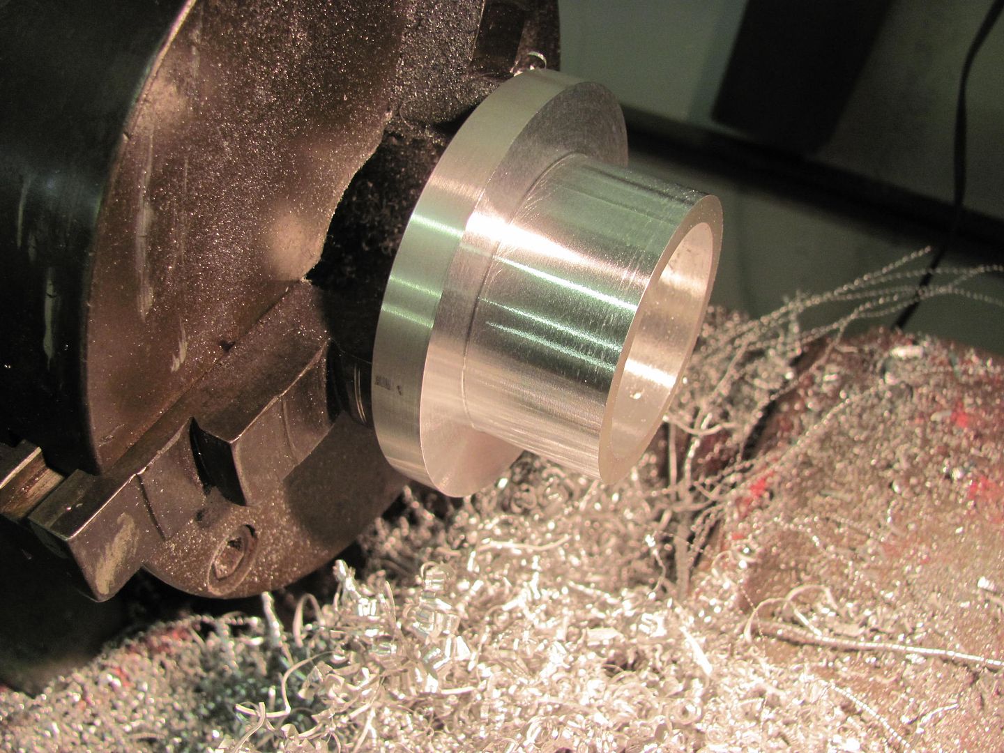
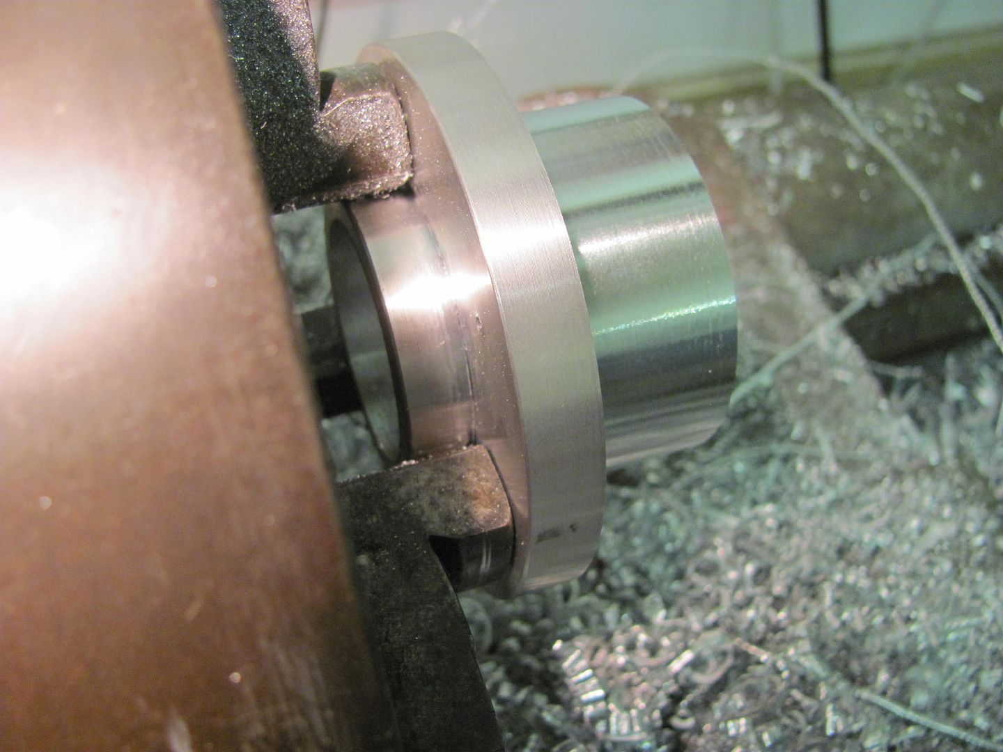
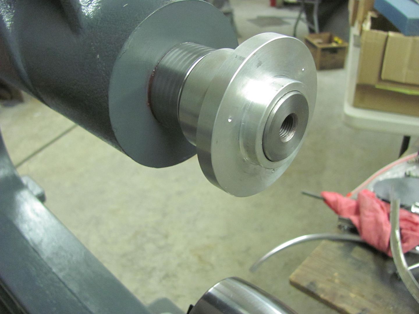
I had stopped at a local machine shop and picked up a 3-1/2" diameter slug left over from their water jet. After some cleanup work on the South Bend, and a clearance hole for the 35mm upper shaft on the wheeling machine...
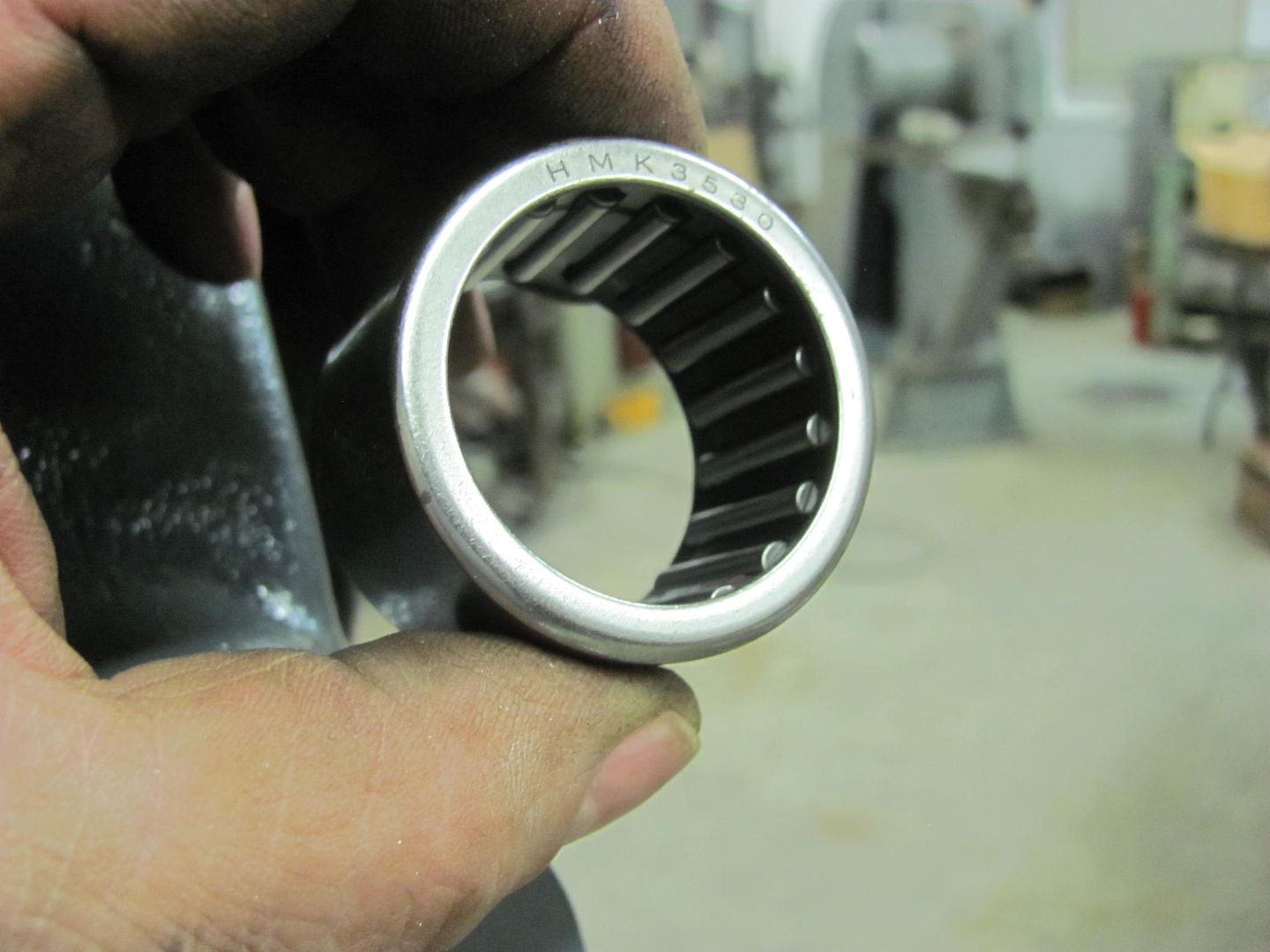
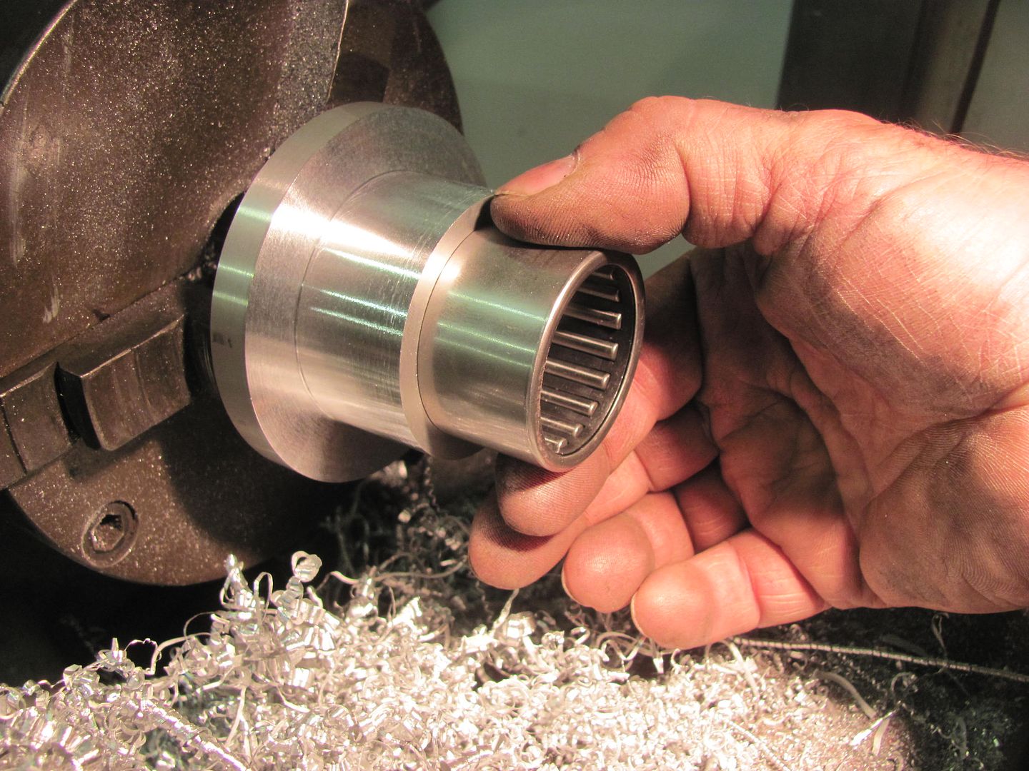
I had found this roller bearing (35mm ID) on ebay, as well as this thrust bearing...
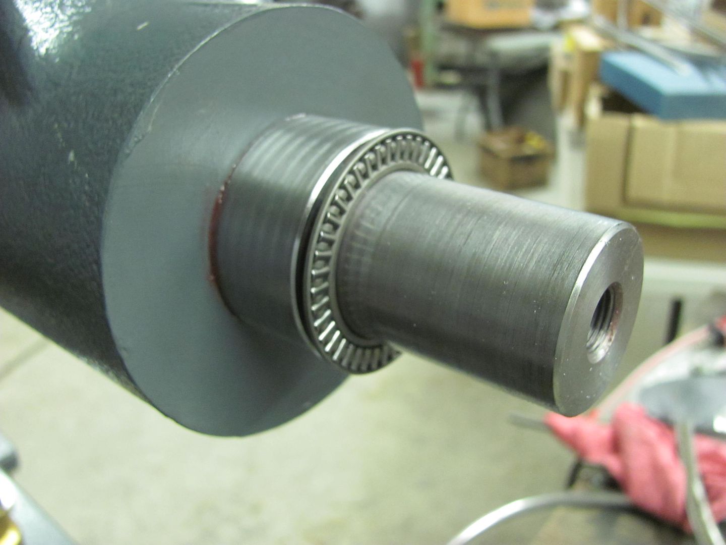
Getting close...
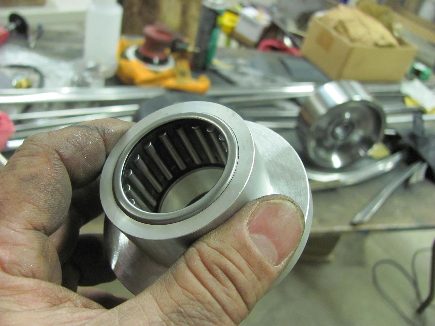
Bearing installed....
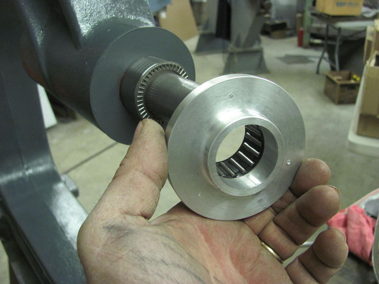
With slick held in place, the alignment looks pretty good...
Motion picture version....
https://www.youtube.com/watch?v=HwVhZzGkBCE
Still need to drill and tap the three lug holes and install the outer thrust bearing.. and then we can get working on the re-skinning of the glove box door..
Tuesday afternoon we loaded up the wagon and dropped it off for media blasting.. should pick it up this weekend.
Tonight I worked on getting the Go Kart Slick hub fabricated for the wheeling machine..
I had stopped at a local machine shop and picked up a 3-1/2" diameter slug left over from their water jet. After some cleanup work on the South Bend, and a clearance hole for the 35mm upper shaft on the wheeling machine...
I had found this roller bearing (35mm ID) on ebay, as well as this thrust bearing...
Getting close...
Bearing installed....
With slick held in place, the alignment looks pretty good...
Motion picture version....
https://www.youtube.com/watch?v=HwVhZzGkBCE
Still need to drill and tap the three lug holes and install the outer thrust bearing.. and then we can get working on the re-skinning of the glove box door..
MP&C
Member
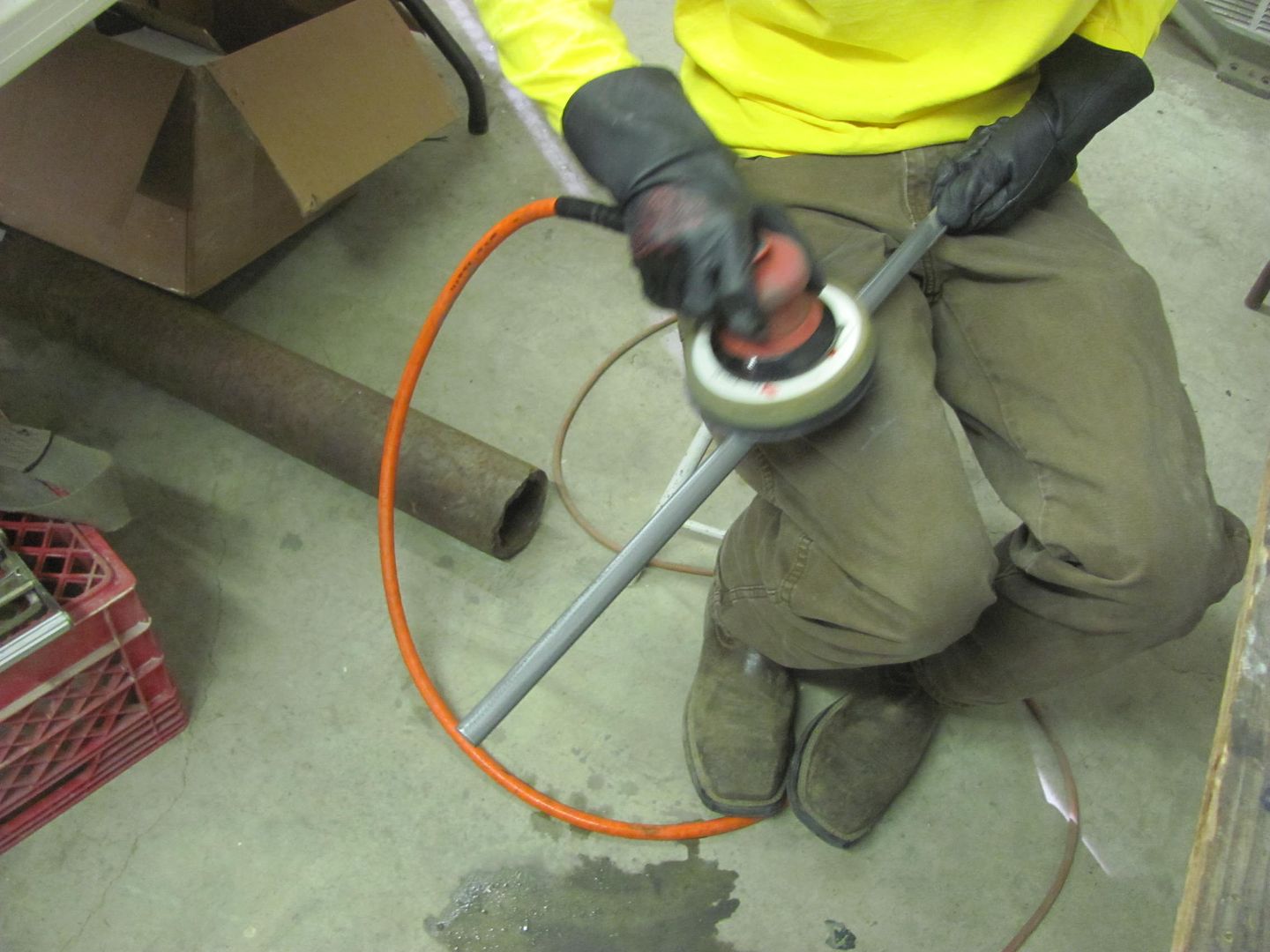
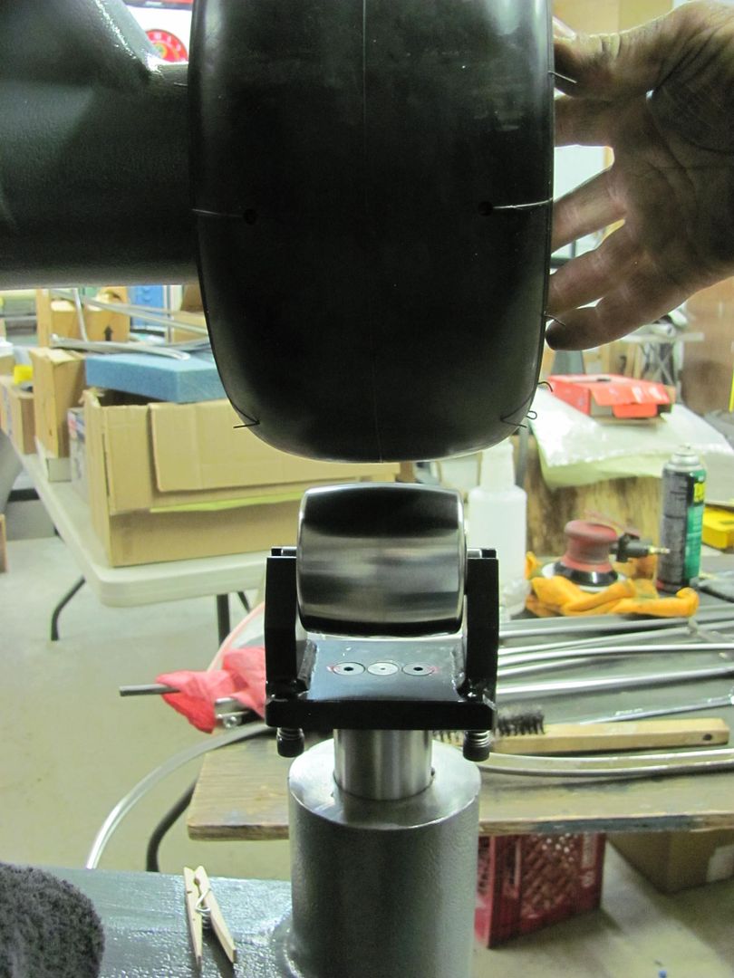
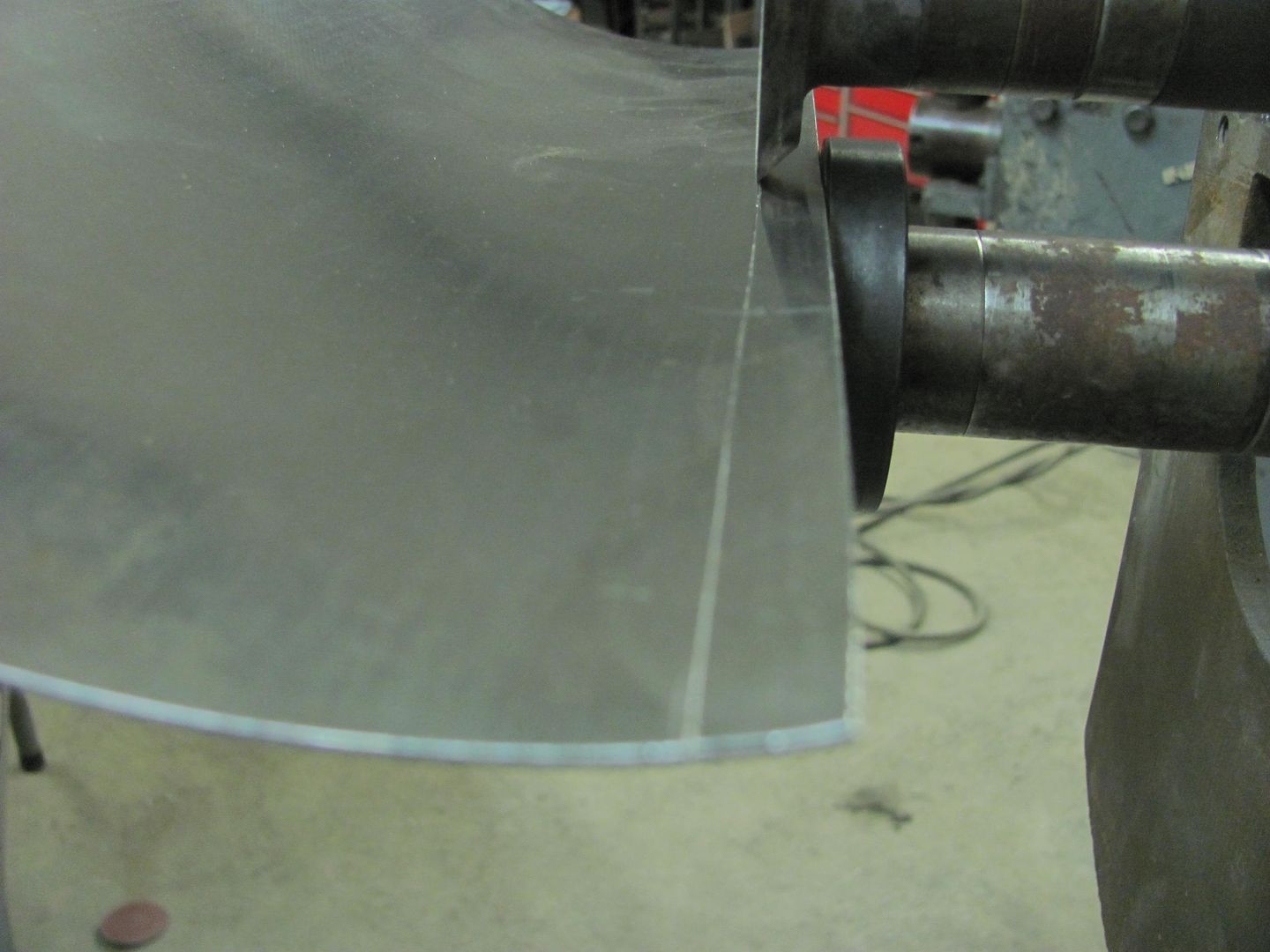
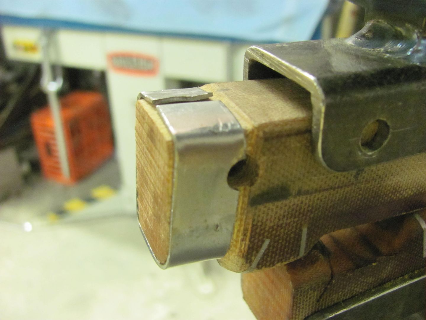
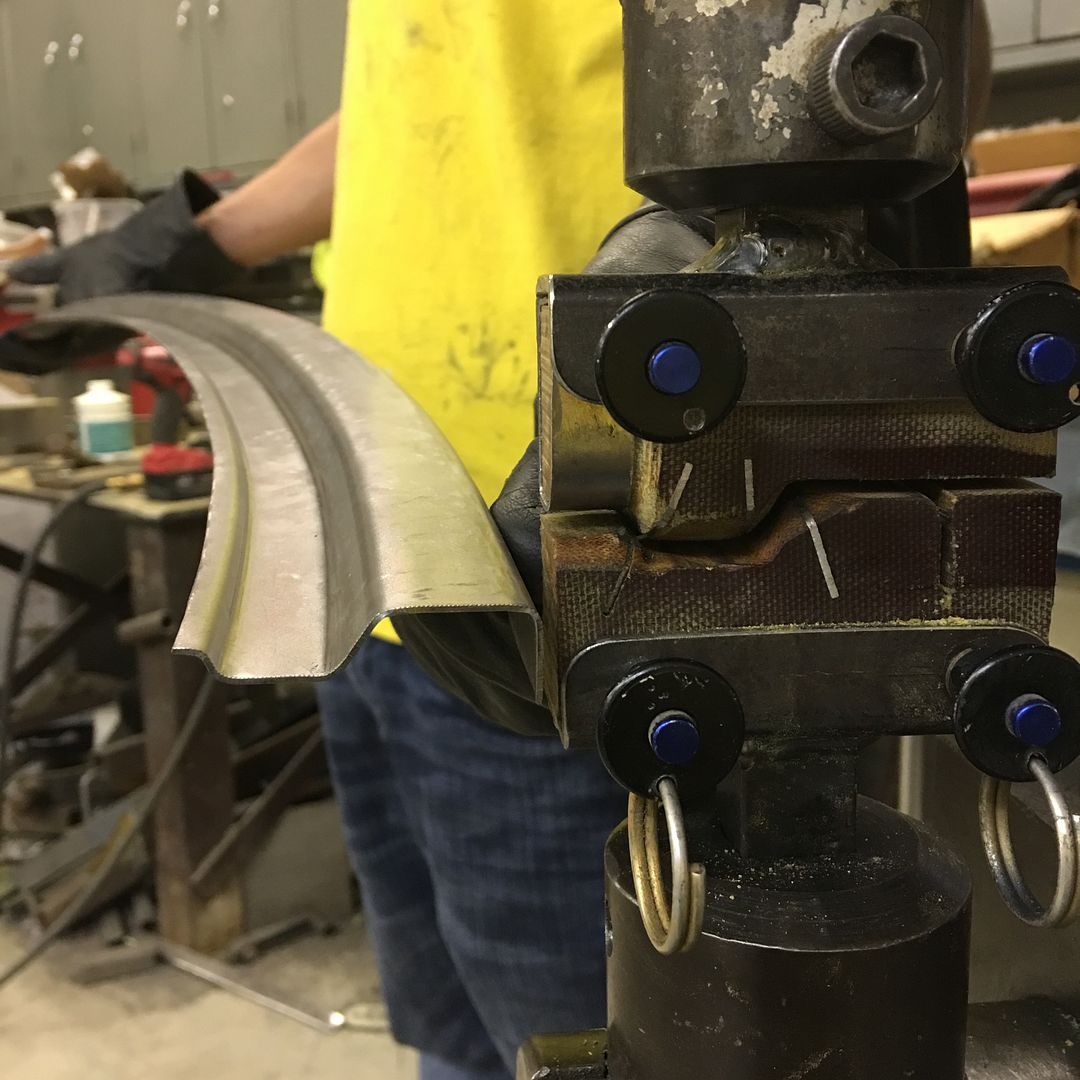
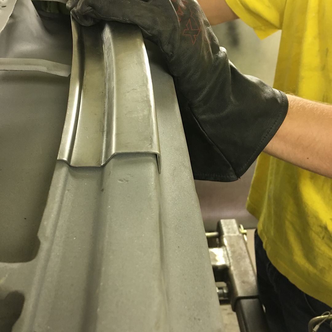
Well today was our Saturday so we put the newly installed GoKart slick to use on the cast wheeling machine, along with the 4" diameter lower anvil. Started with slight pressure and gradually increased. Tire was about 1/2 deflated.
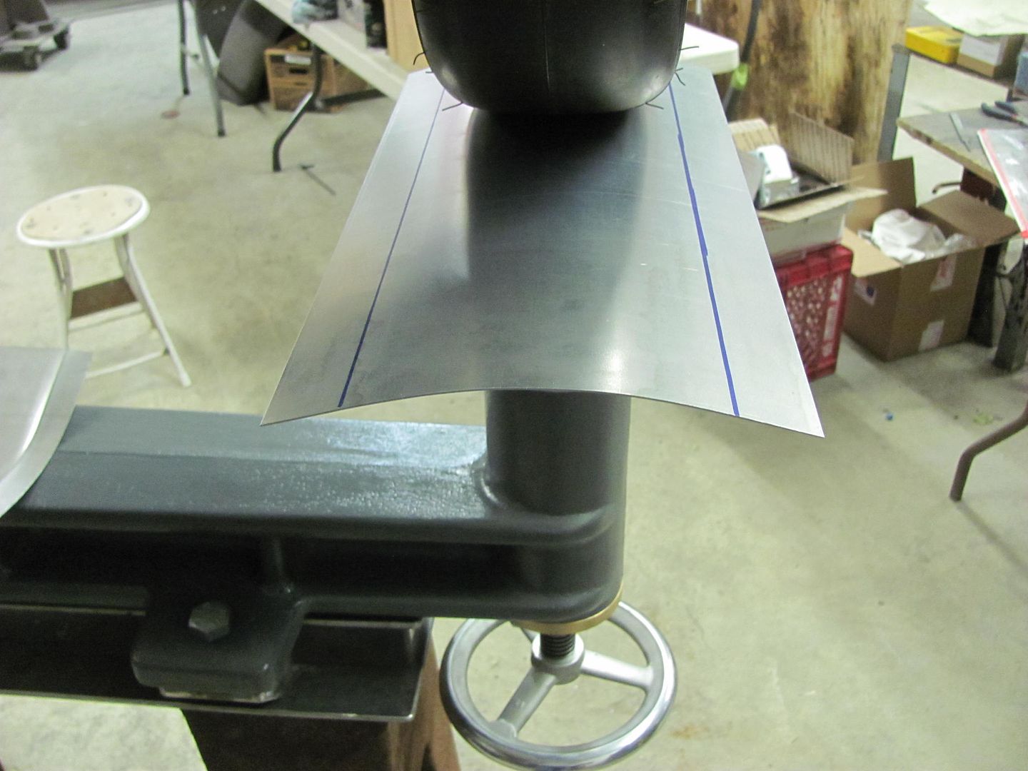
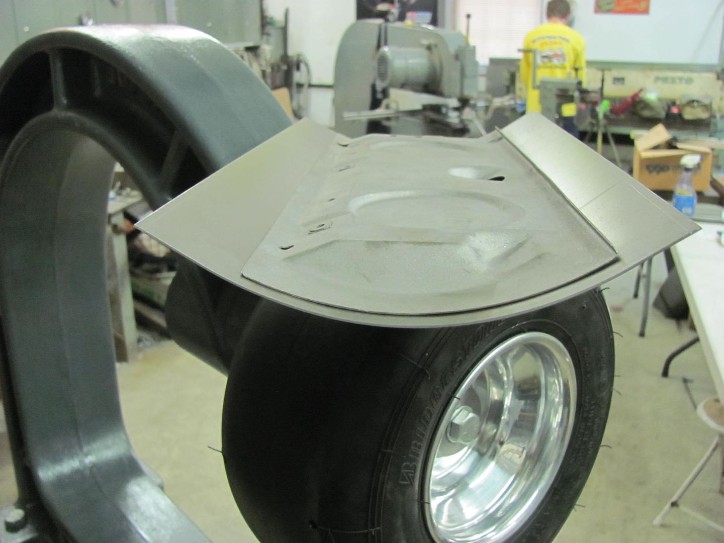
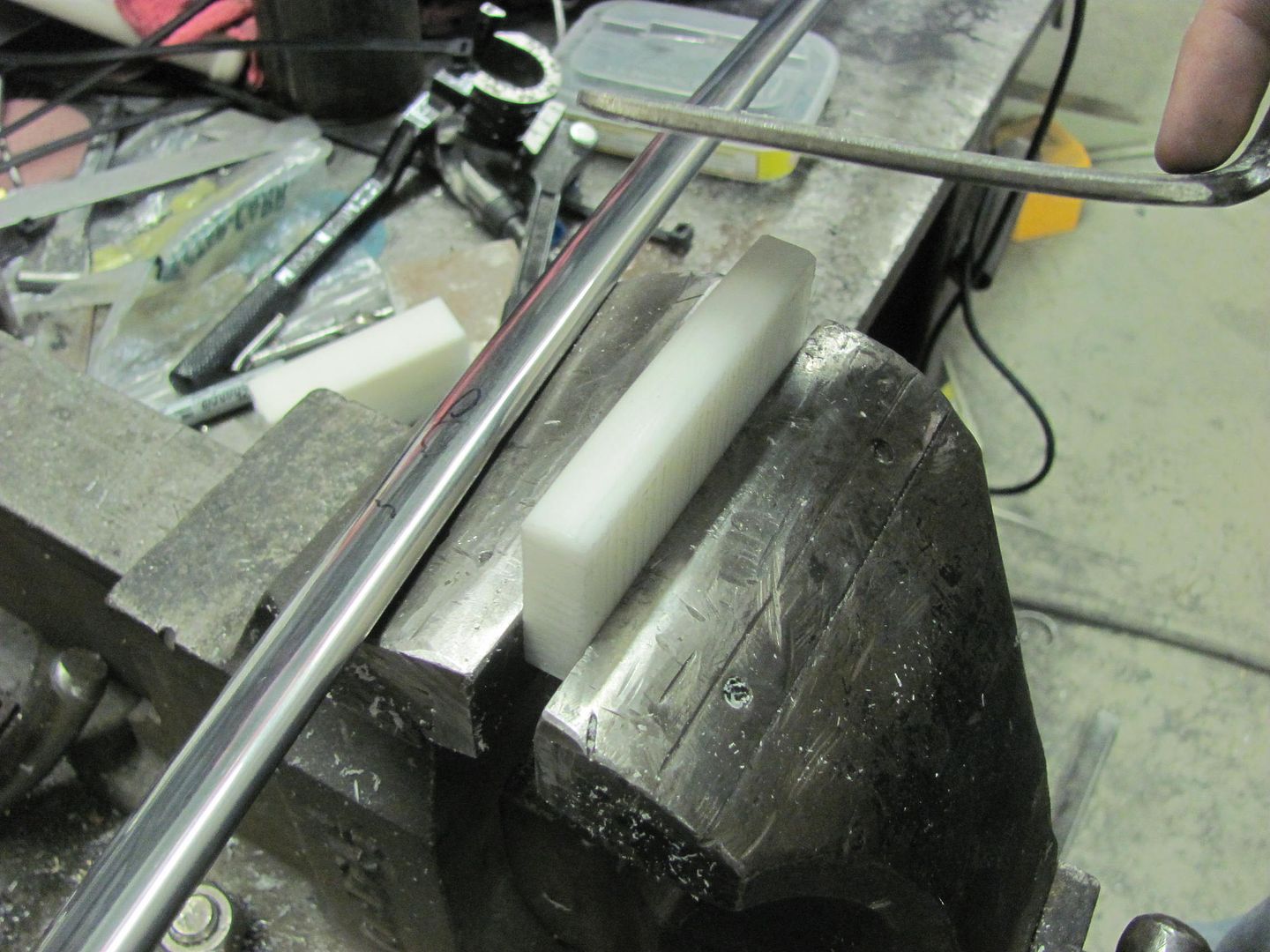
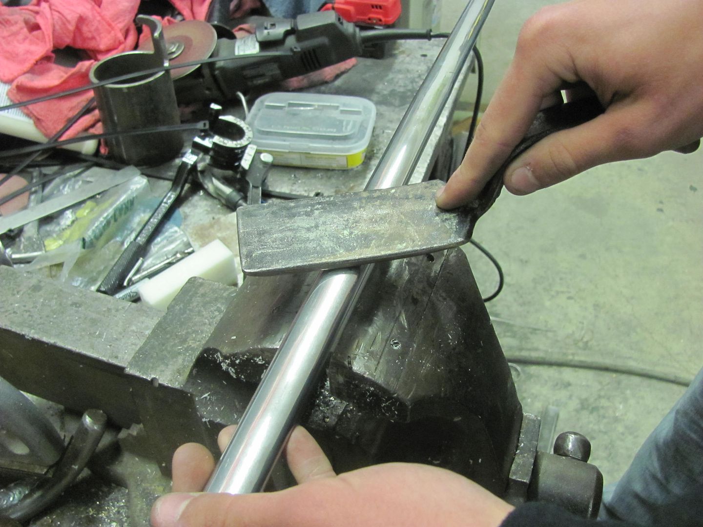
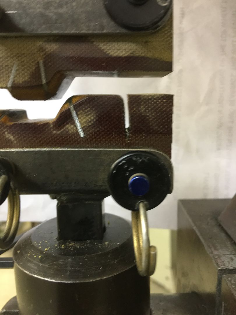
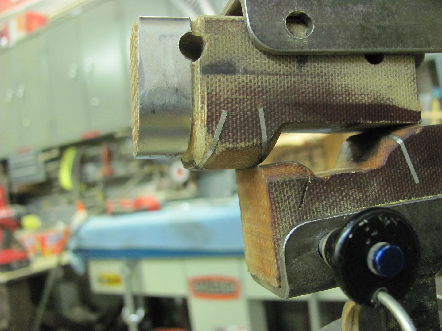
The sides (as shown) had been left a bit long to keep from flattening out fingertips, so now we trimmed one side and marked for the bends. The tipping wheel in the bead roller was used to thin the bend area for a bit of friendly persuasion..
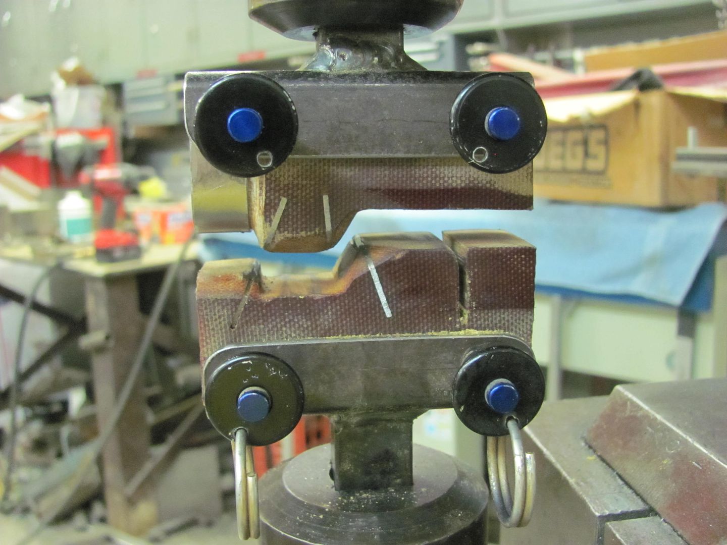
These were fun. About 3/16" from bend to bend....or less. Had to use all the tricks, hem is still loose, we'll epoxy all the pieces apart and then assemble, making all the folds tight.
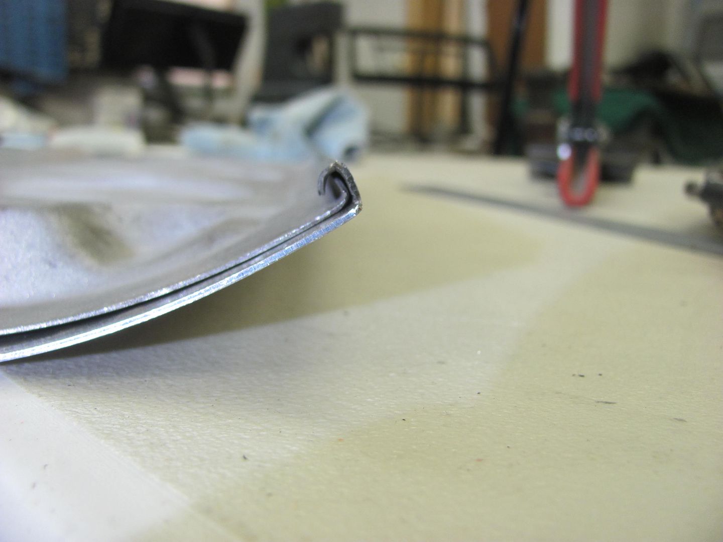
Still have the lock hole to go as well, we are going to leave this one smooth as opposed to the factory's vertical bead to simulate the gap at the ashtray..
The sides (as shown) had been left a bit long to keep from flattening out fingertips, so now we trimmed one side and marked for the bends. The tipping wheel in the bead roller was used to thin the bend area for a bit of friendly persuasion..
These were fun. About 3/16" from bend to bend....or less. Had to use all the tricks, hem is still loose, we'll epoxy all the pieces apart and then assemble, making all the folds tight.
Still have the lock hole to go as well, we are going to leave this one smooth as opposed to the factory's vertical bead to simulate the gap at the ashtray..
MP&C
Member
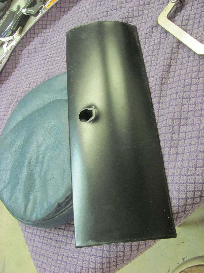
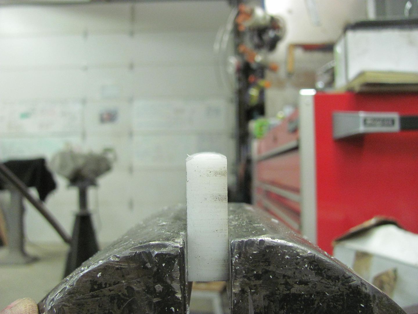
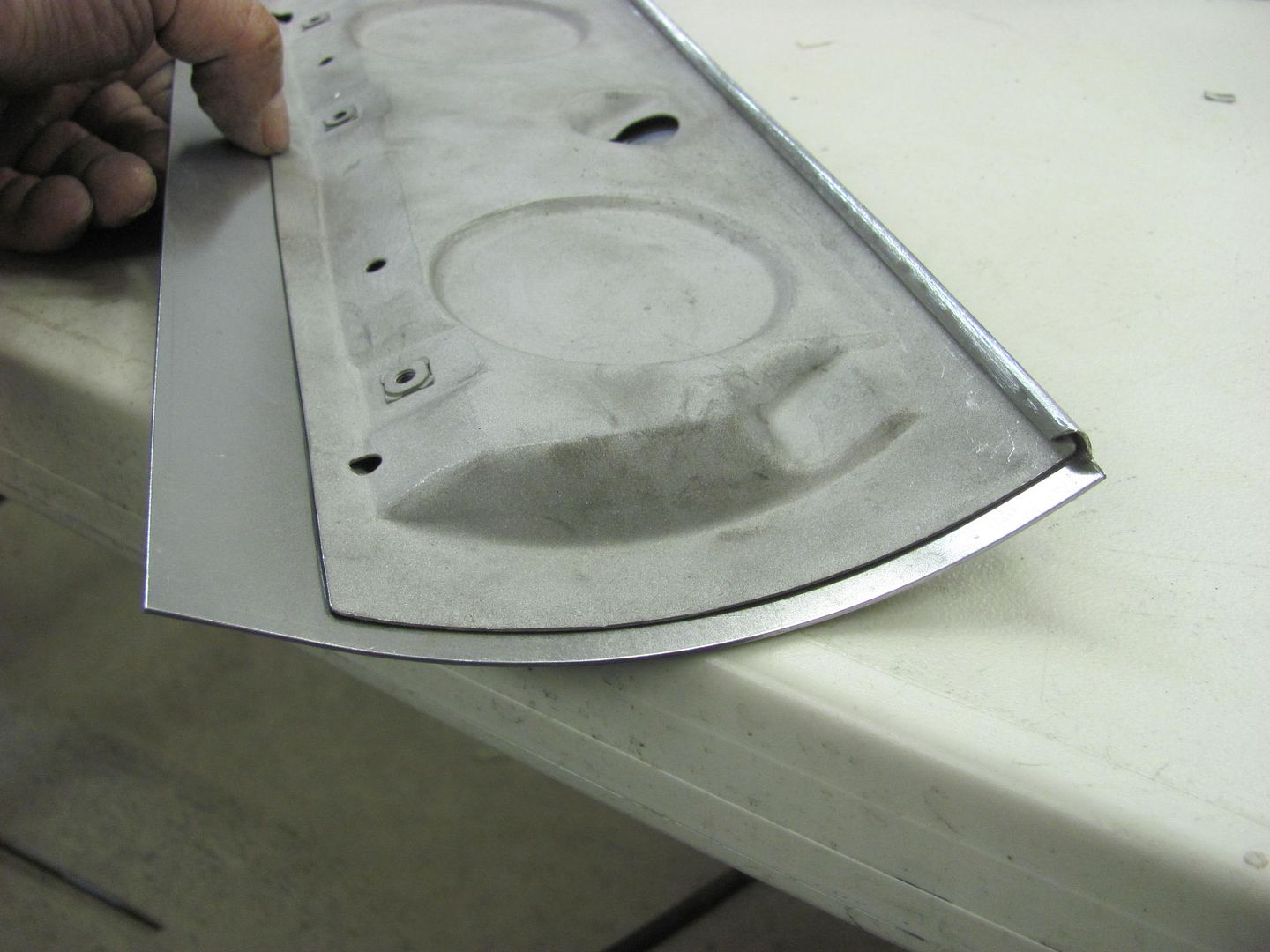
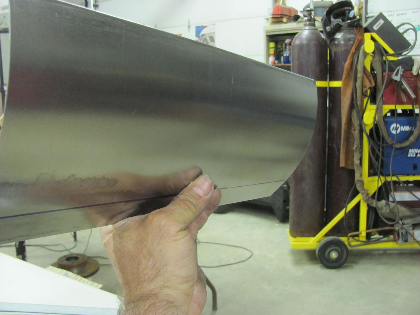
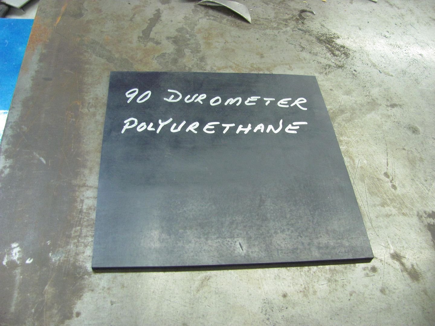
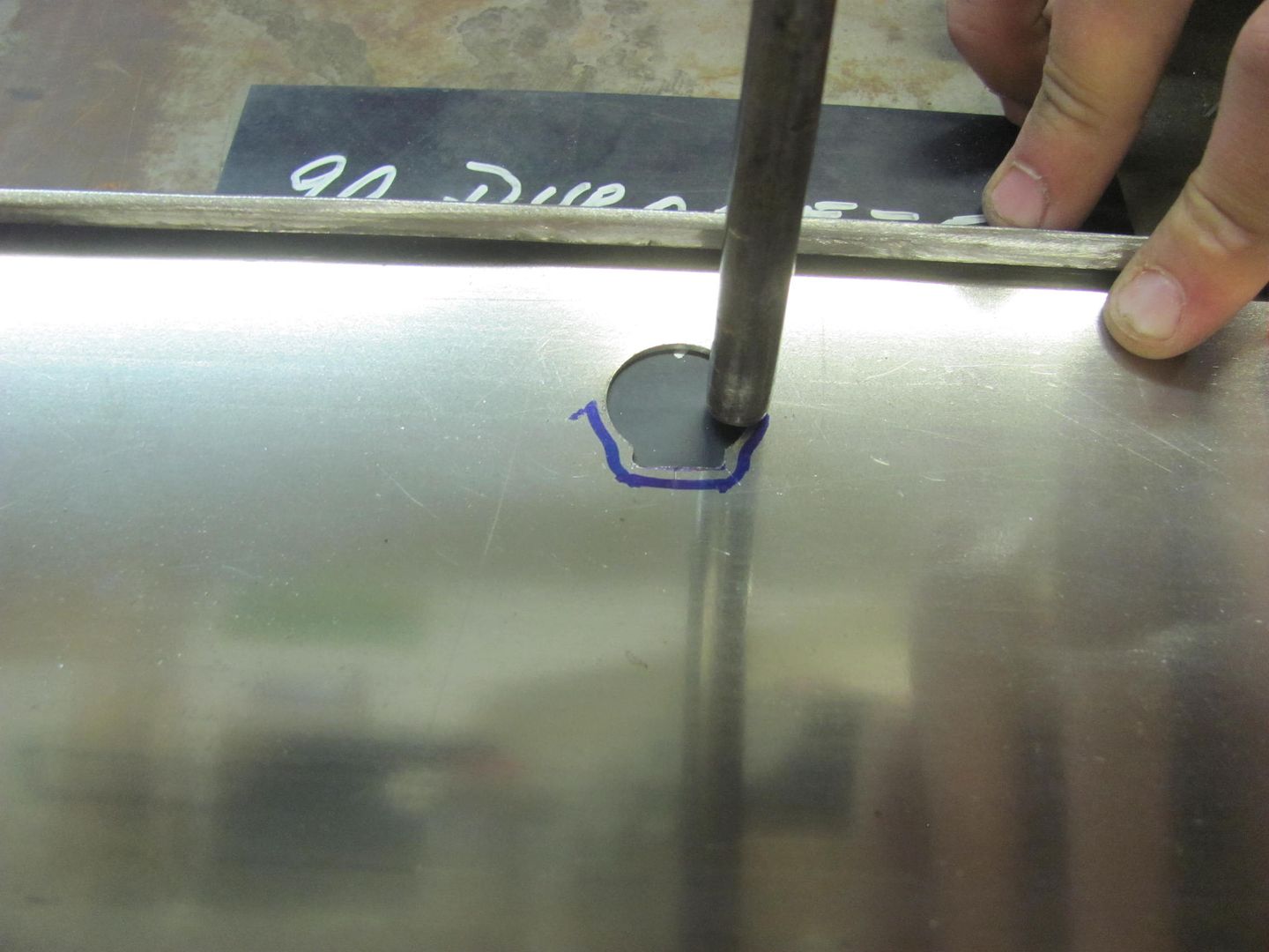
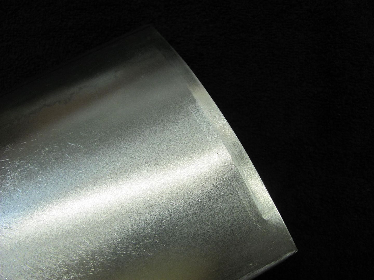
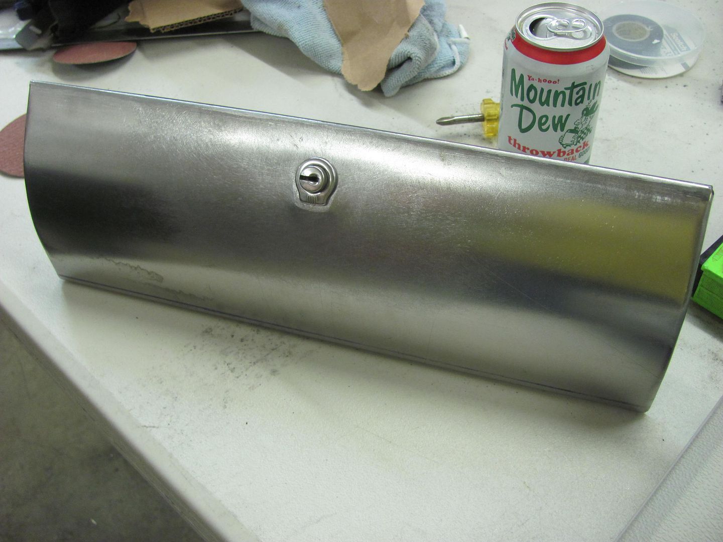
Well with a nice radius on the face of the glove box door skin, we now need a flat area for the lock cylinder. Since I had a piece of Polyurethane here from the care package Rich B had sent me, it seemed the right tool for the job.
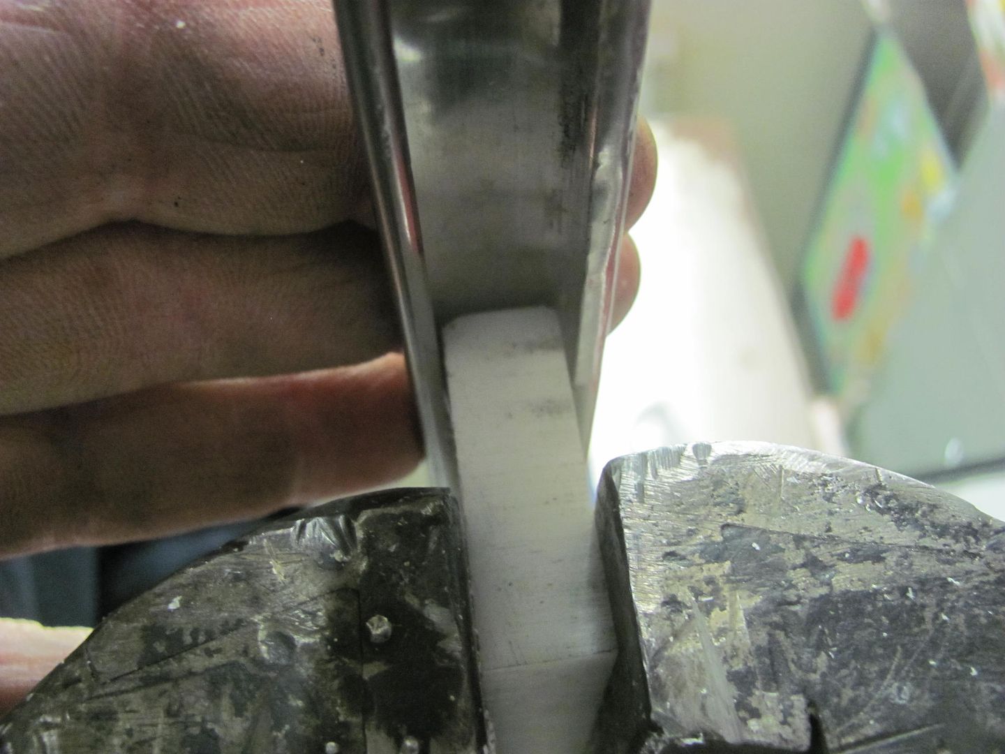
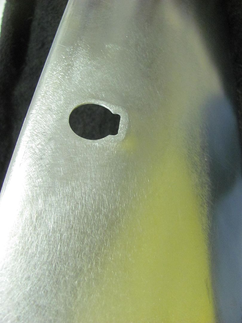
The lock cylinder hole was added using a step drill for the hole and a die grinder for the notch.
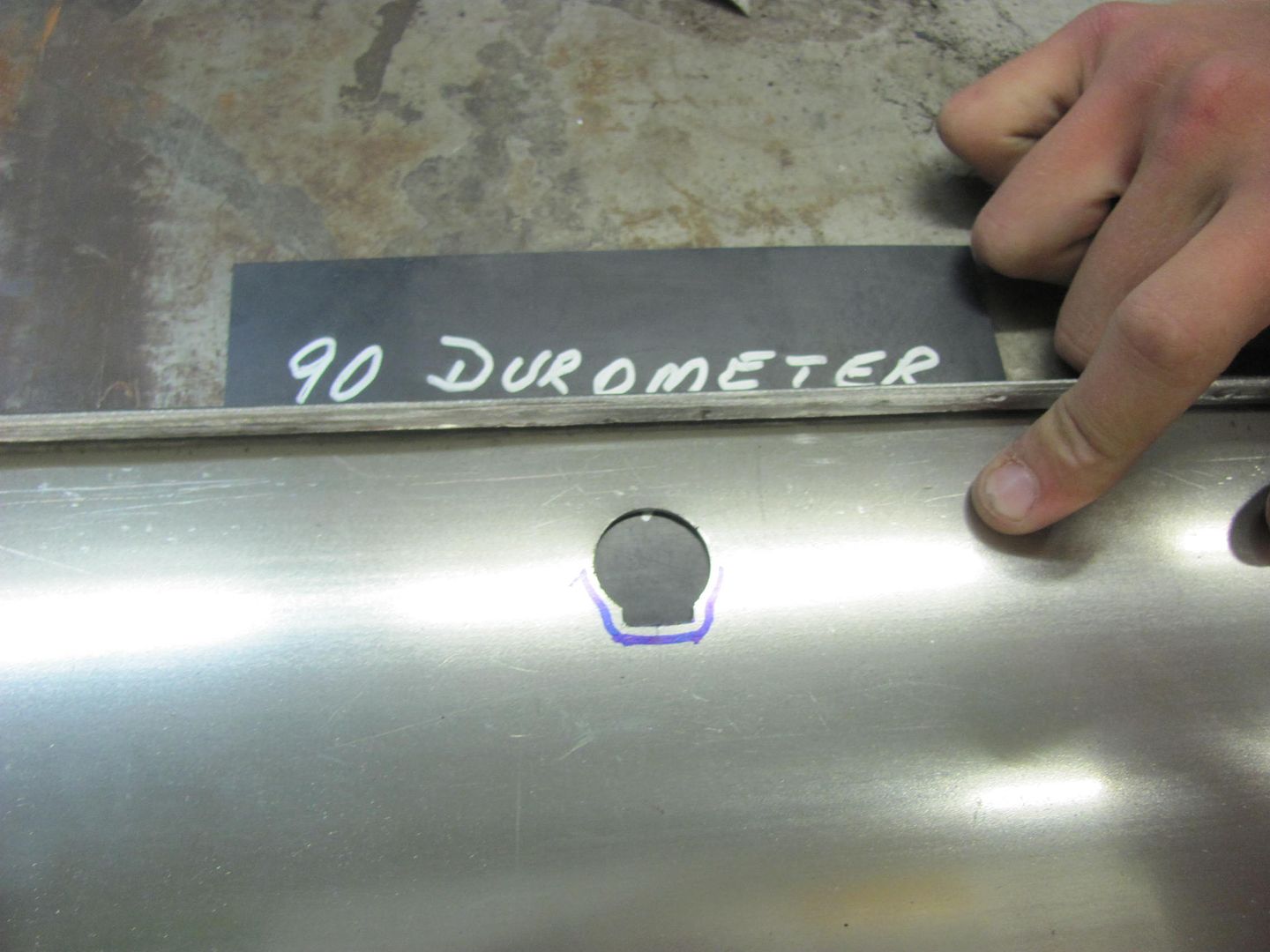
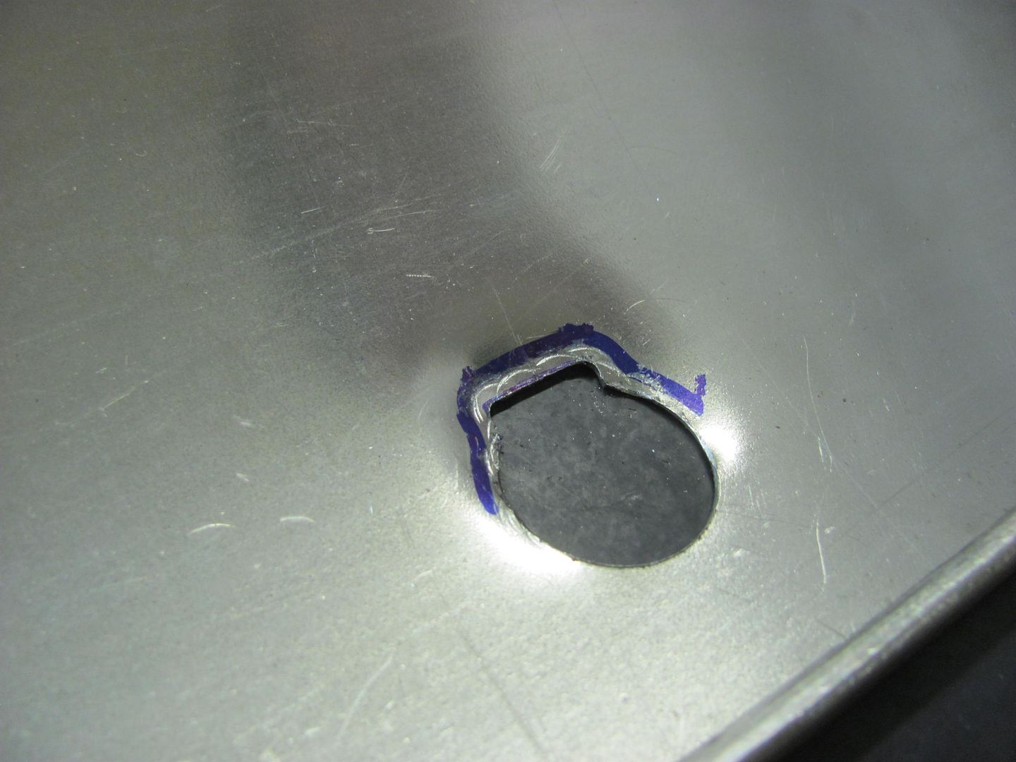
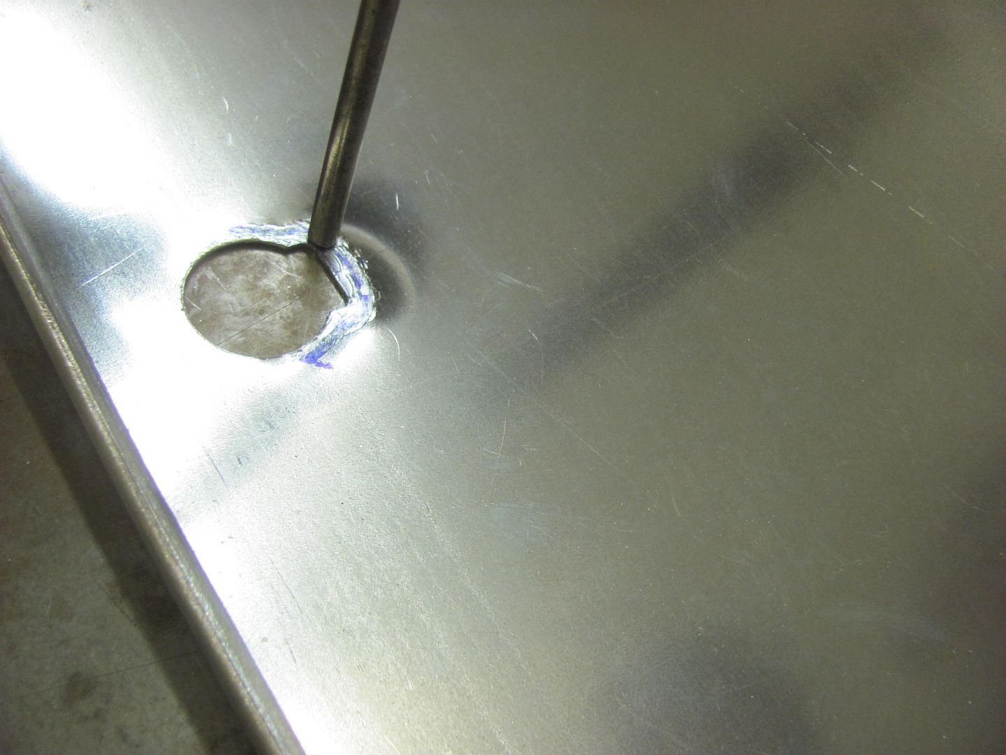
A punch is used to add the needed stretch to provide the flat area..
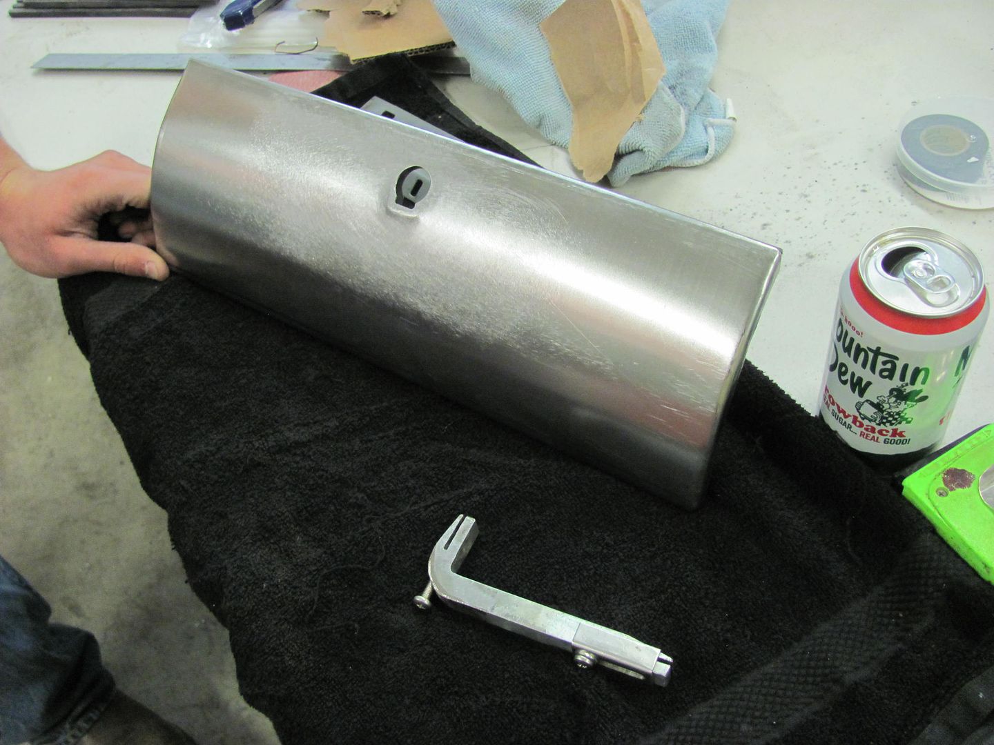
Starting to take shape..
Some fine tuning of the detail...
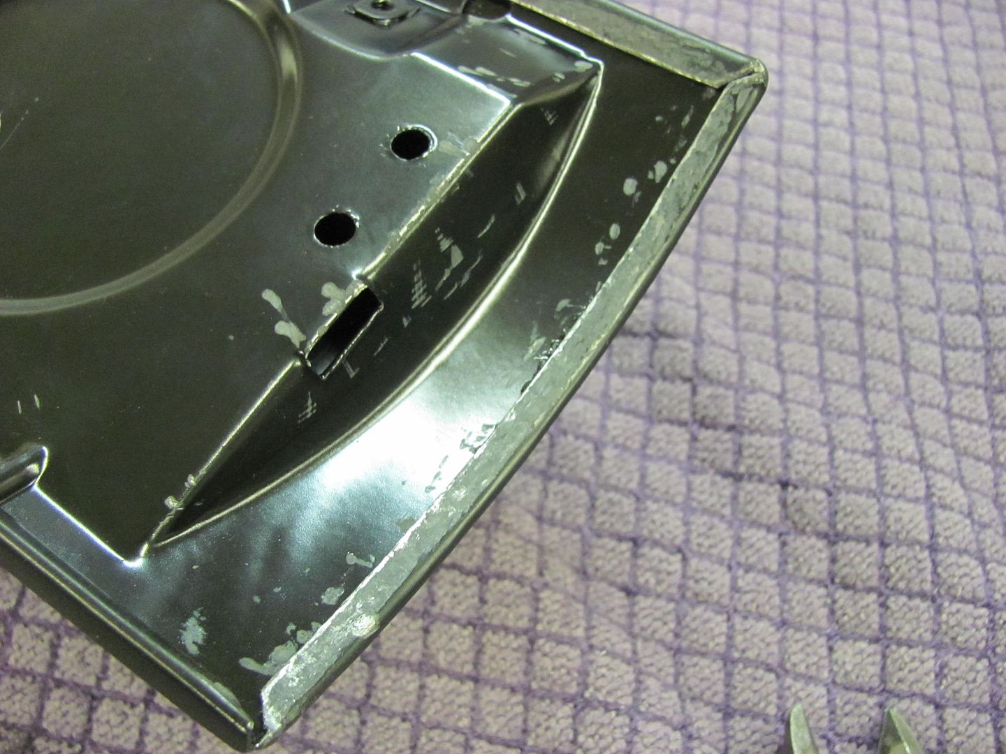
The bottom flange was measured, trimmed, and folded in the Diacro press brake
The side flanges were tipped slightly in the Bead Roller.. This also gives us a nice mark to show the fold line..
Touched up with the DA
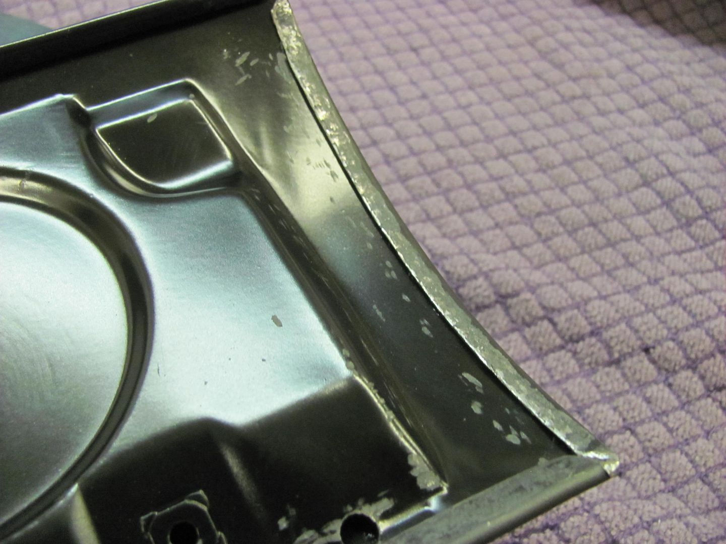
With the three flanges folded to a 90, now we'll media blast and epoxy before assembling the two halves.
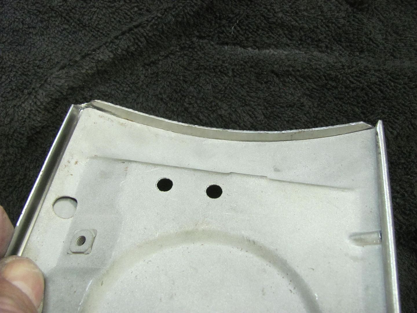
This shows the tipping tool used on the side flanges.
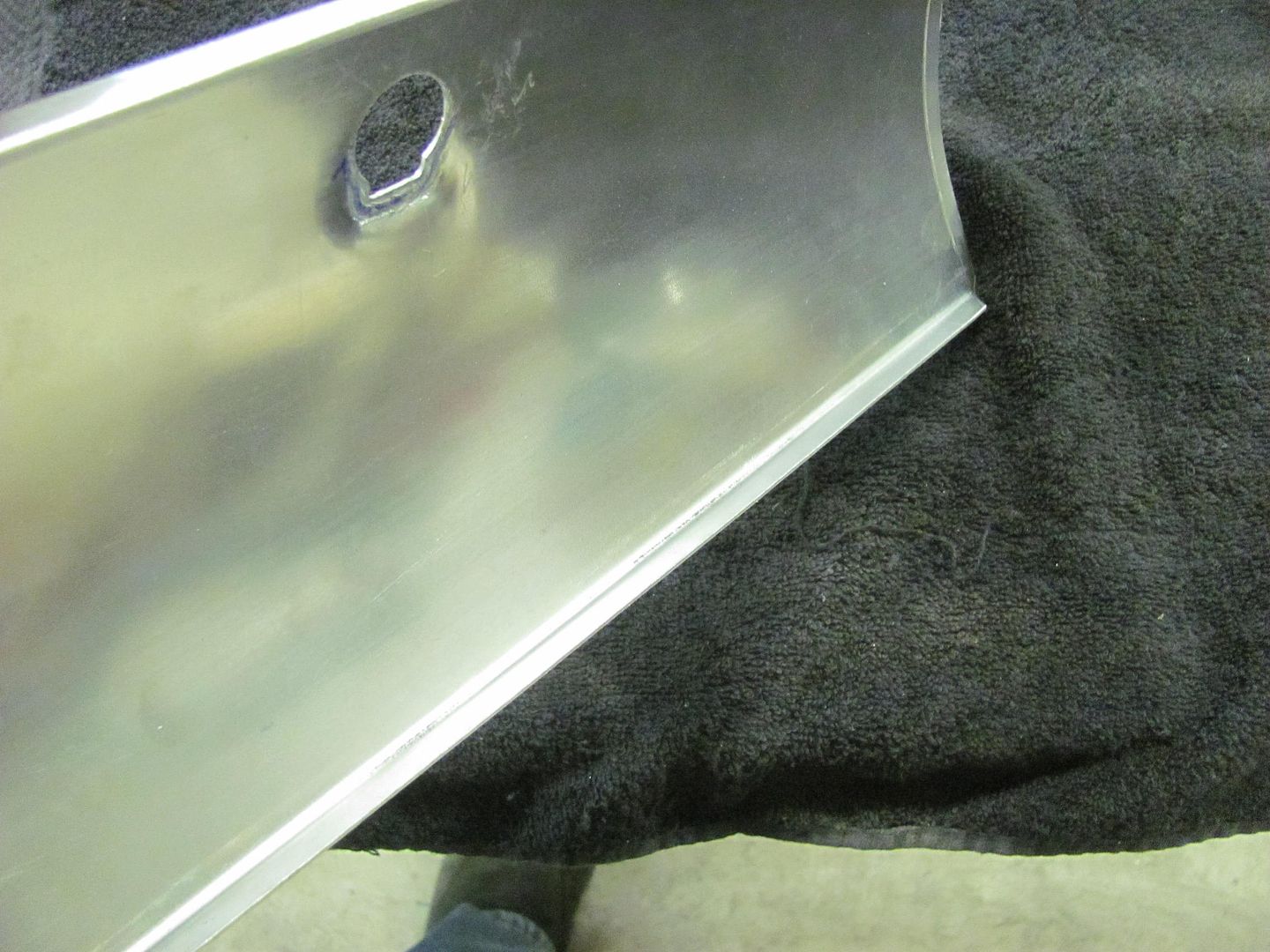
With lock cylinder. Looks almost factory...
The lock cylinder hole was added using a step drill for the hole and a die grinder for the notch.
A punch is used to add the needed stretch to provide the flat area..
Starting to take shape..
Some fine tuning of the detail...
The bottom flange was measured, trimmed, and folded in the Diacro press brake
The side flanges were tipped slightly in the Bead Roller.. This also gives us a nice mark to show the fold line..
Touched up with the DA
With the three flanges folded to a 90, now we'll media blast and epoxy before assembling the two halves.
This shows the tipping tool used on the side flanges.
With lock cylinder. Looks almost factory...
MP&C
Member
Thanks!
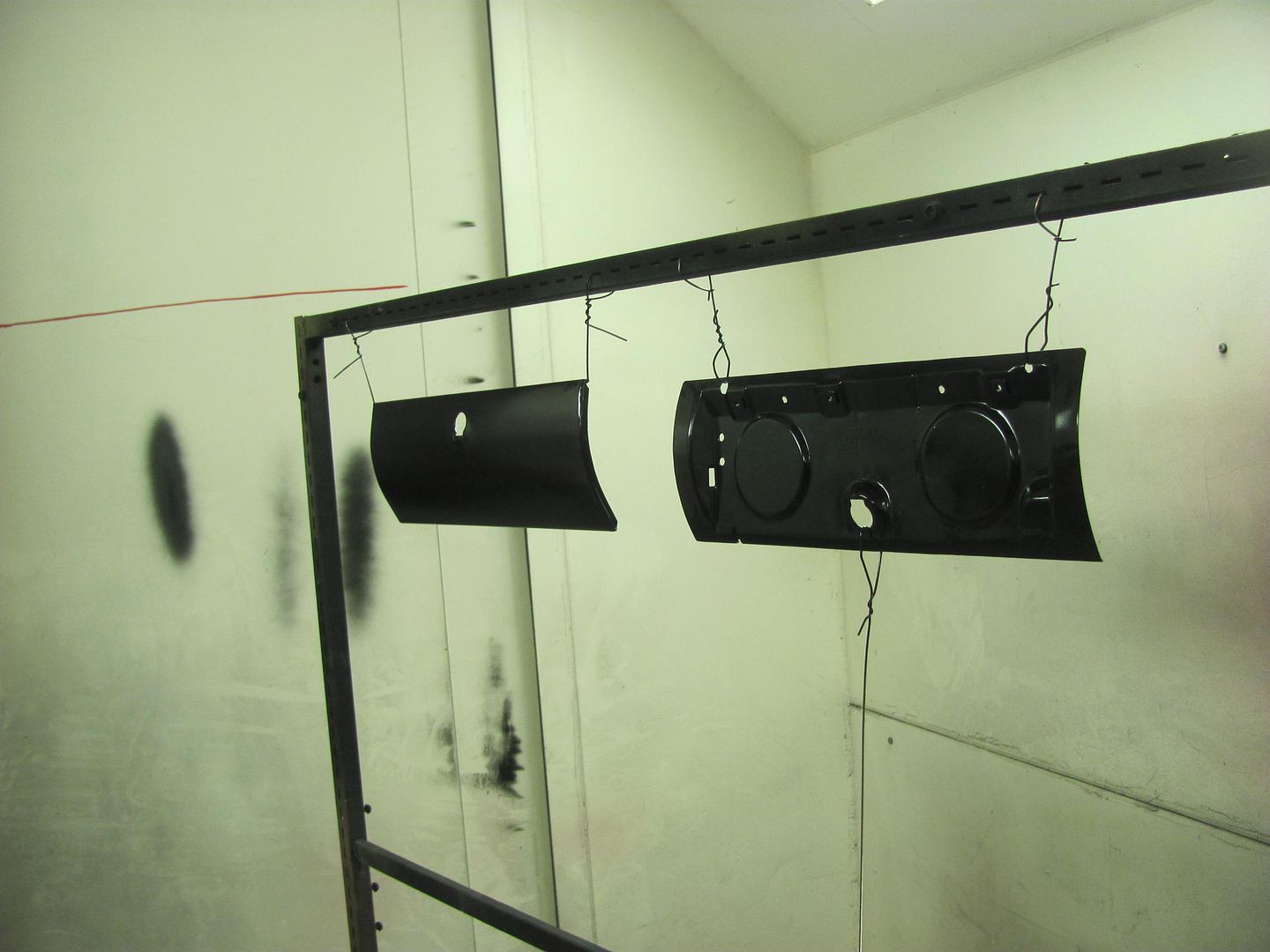
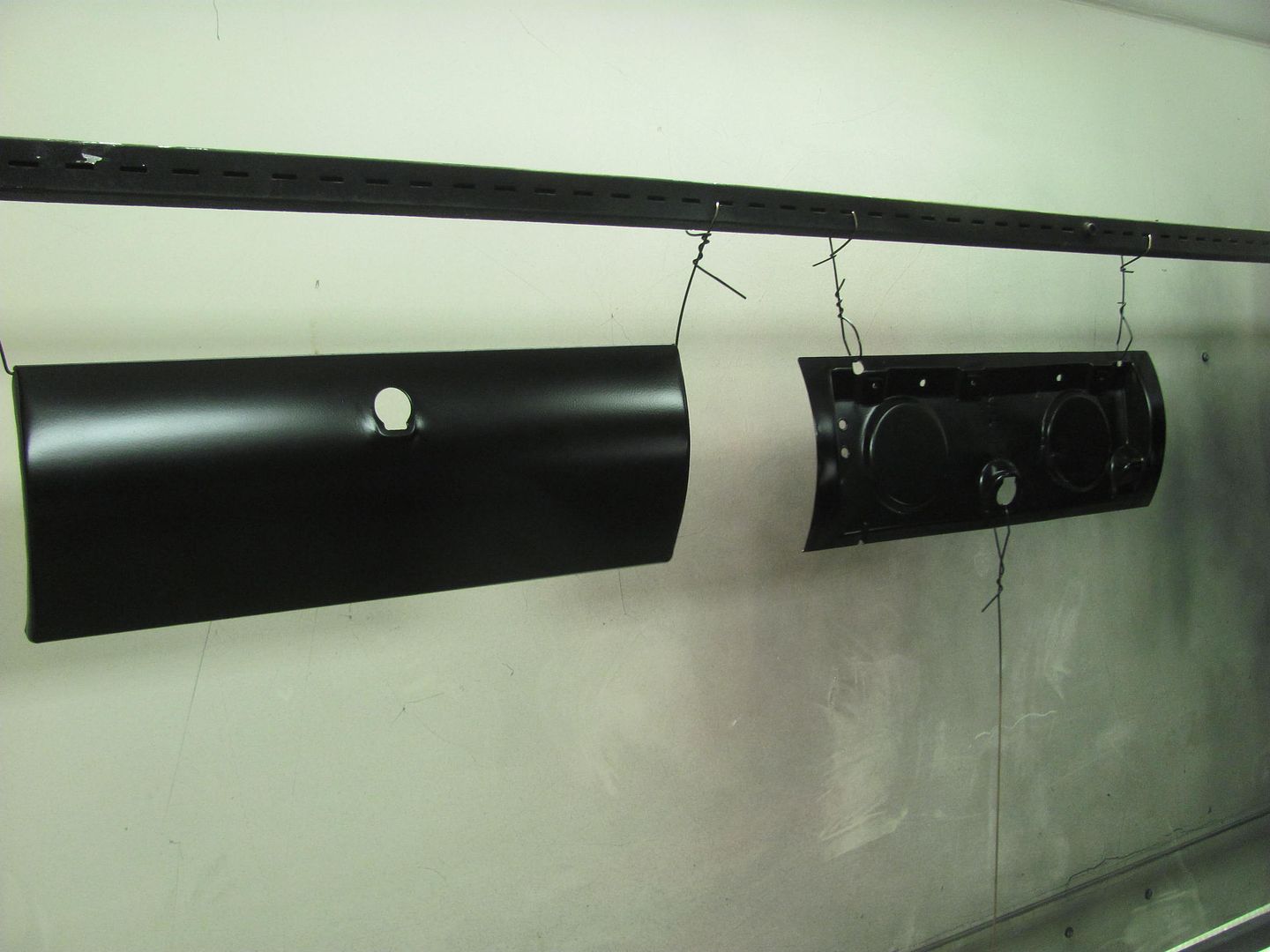
Well last night's efforts saw us media blasting, hanging the next batch of small parts for epoxy primer, and general cleanup.......which has been sorely needed. So we don't have much of interest to show, so let's turn it over to Dana (the owner) who got these parts powder coated yesterday for us...
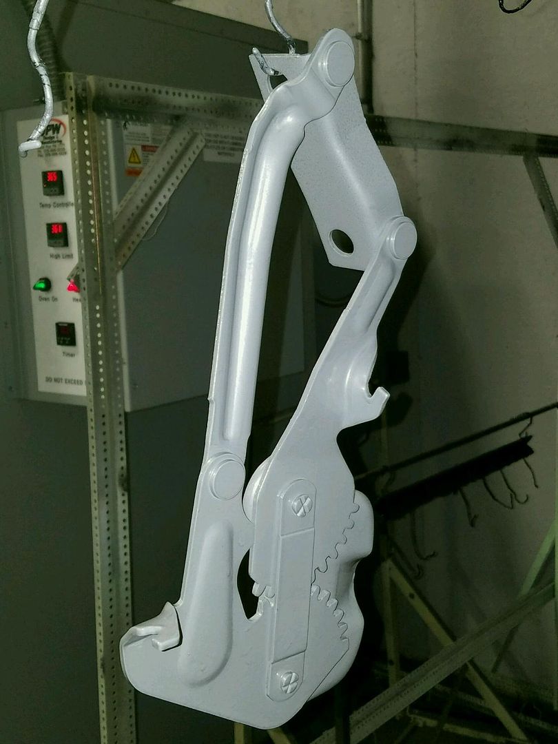
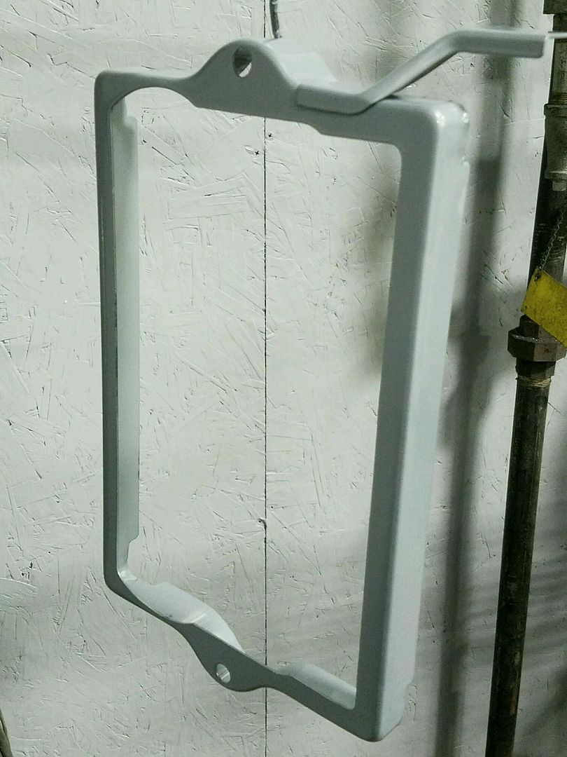
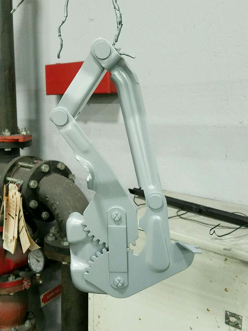
Well last night's efforts saw us media blasting, hanging the next batch of small parts for epoxy primer, and general cleanup.......which has been sorely needed. So we don't have much of interest to show, so let's turn it over to Dana (the owner) who got these parts powder coated yesterday for us...
MP&C
Member
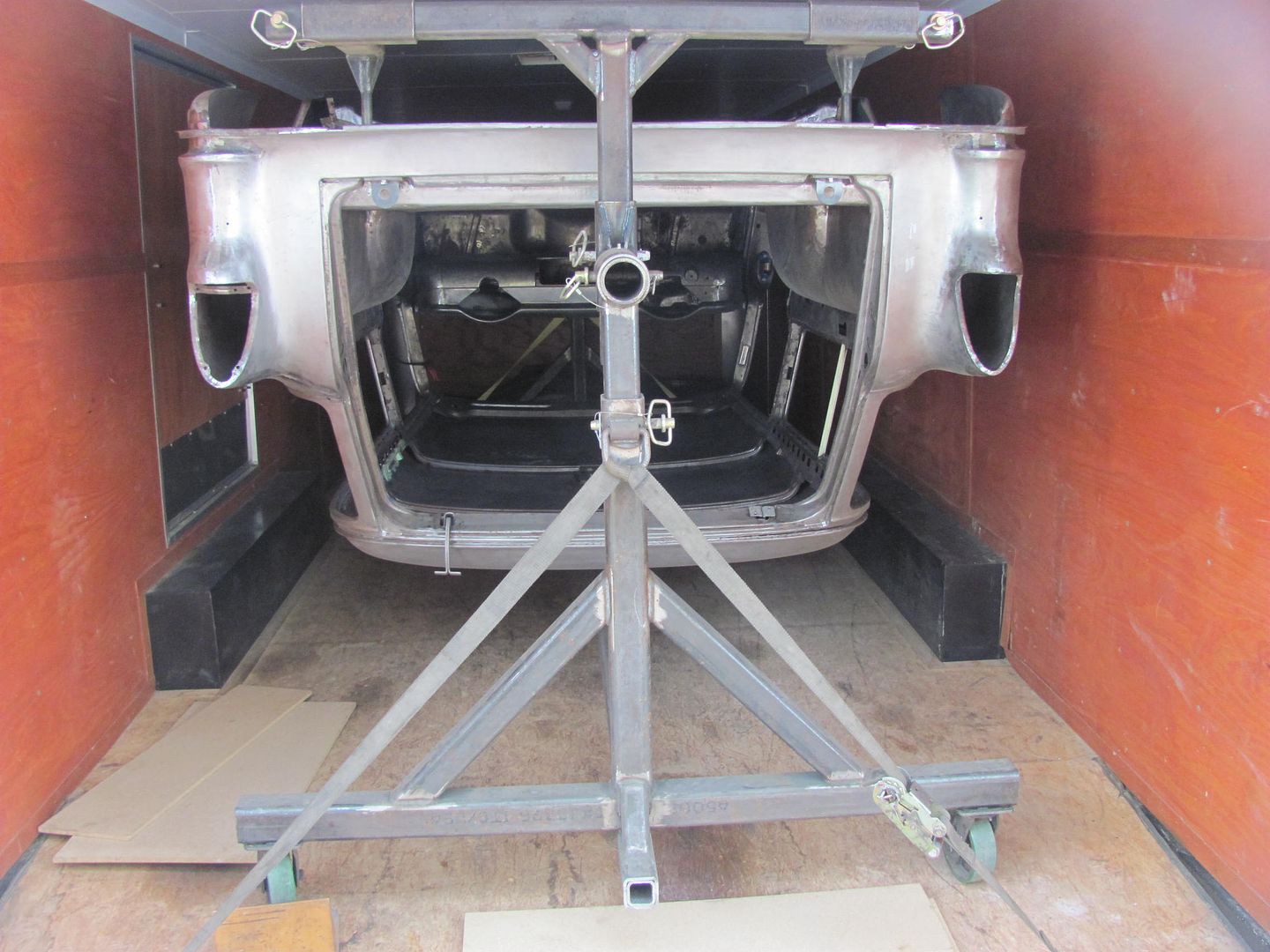
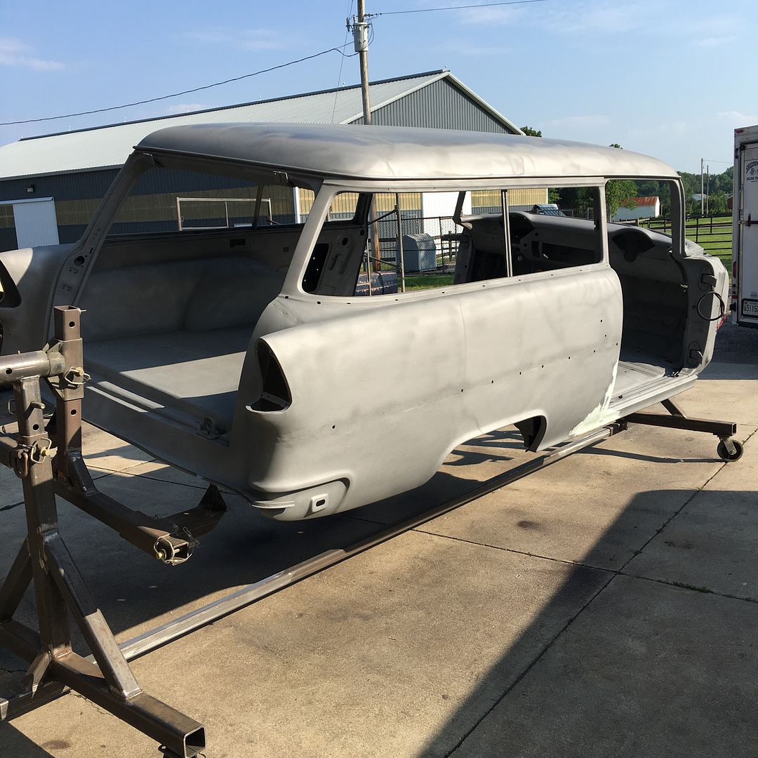
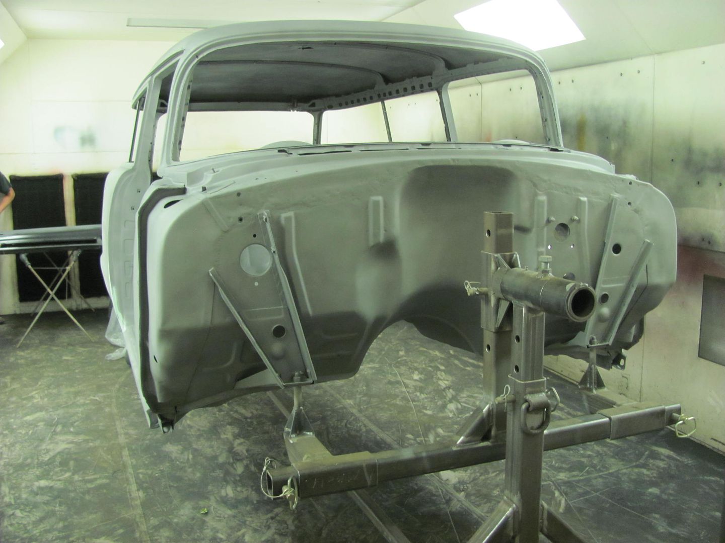
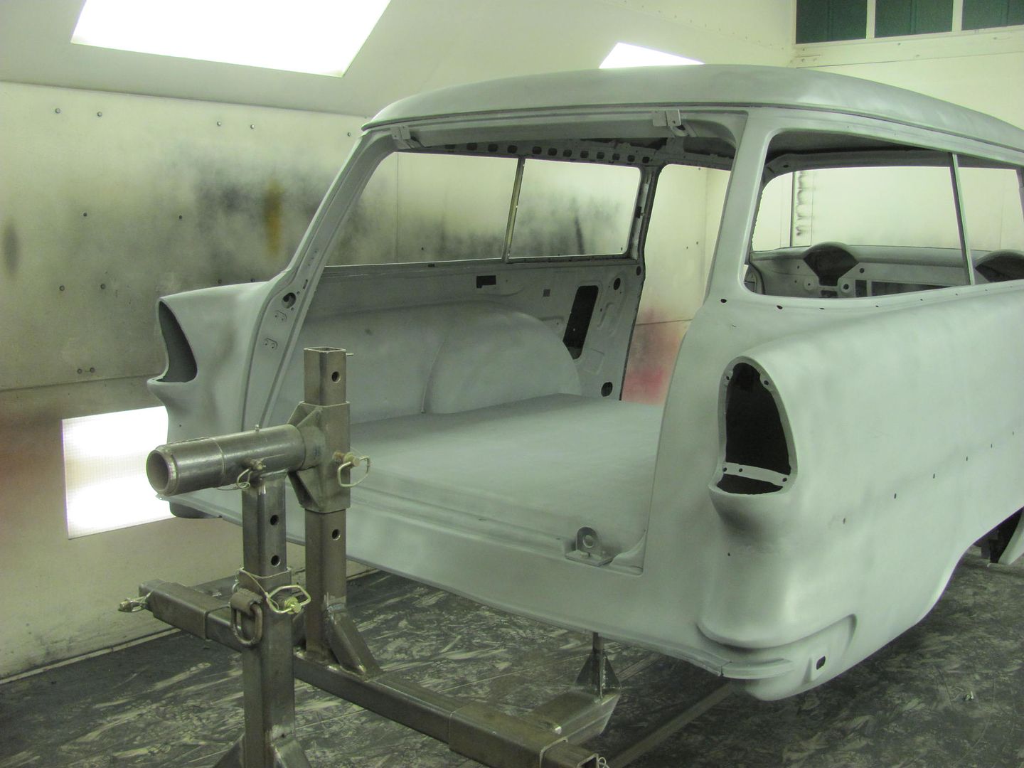
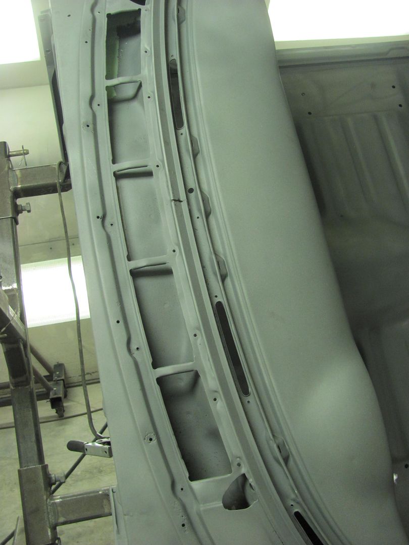
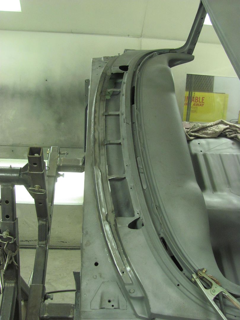
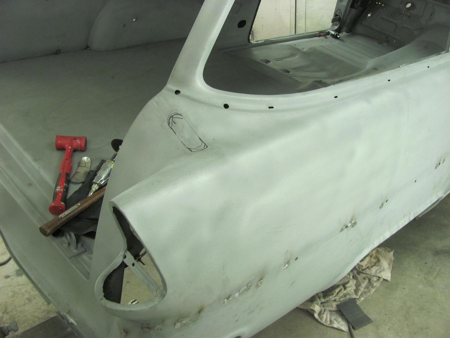
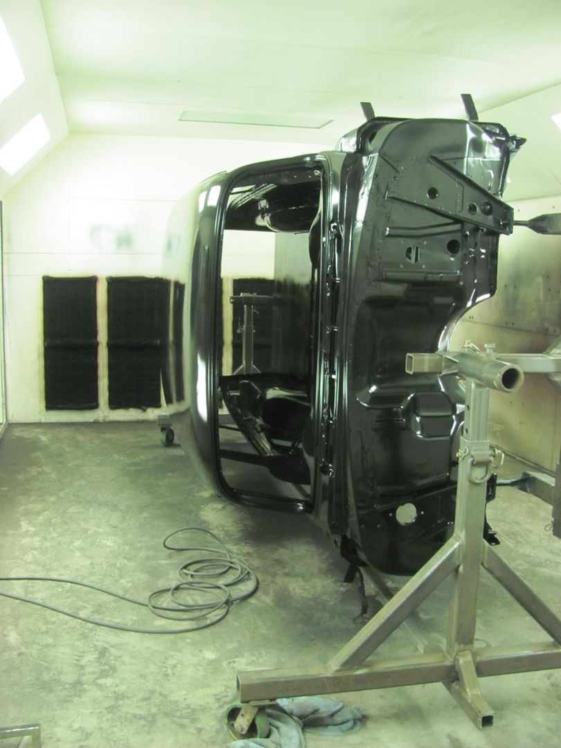
Well the two weeks plus of non stop rain has finally subsided where the media blasting could commence. Got a phone call today that the car was ready to pick up.. Here it is before we loaded it up..
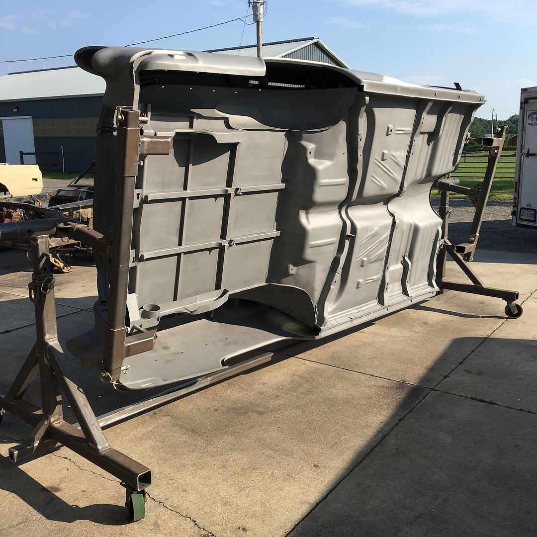
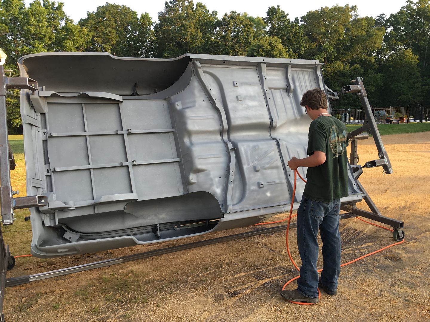
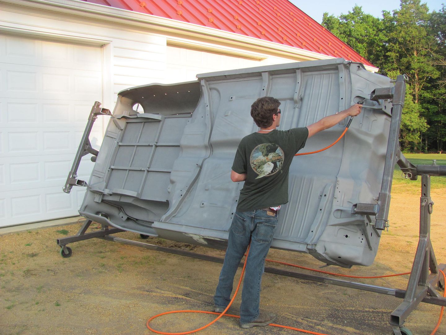
This is the part where you wish you had a tilt bed trailer so any media residue would be persuaded on out on the return trip home... But alas, we found a combination of using the air hose and a shop vac best to evacuate most of the media. That and about 50 or so revolutions on the rotisserie.....
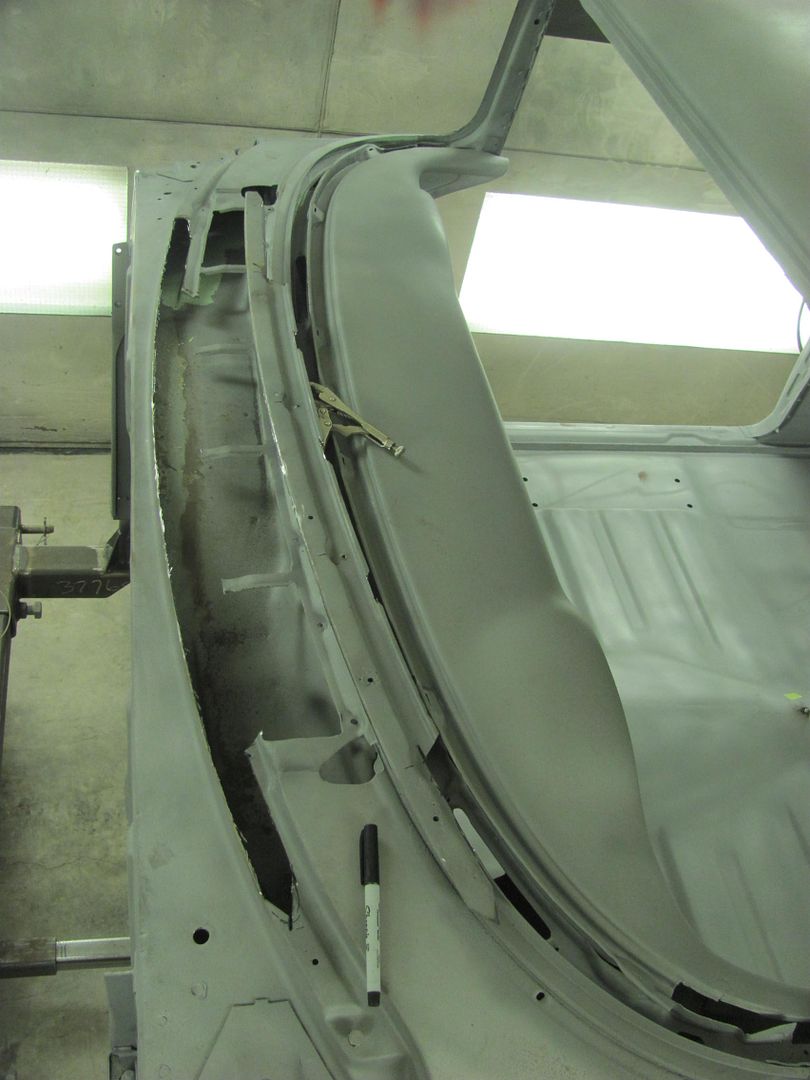
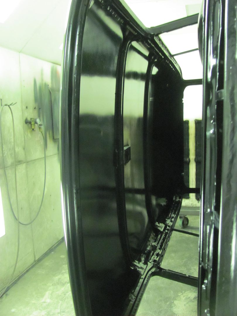
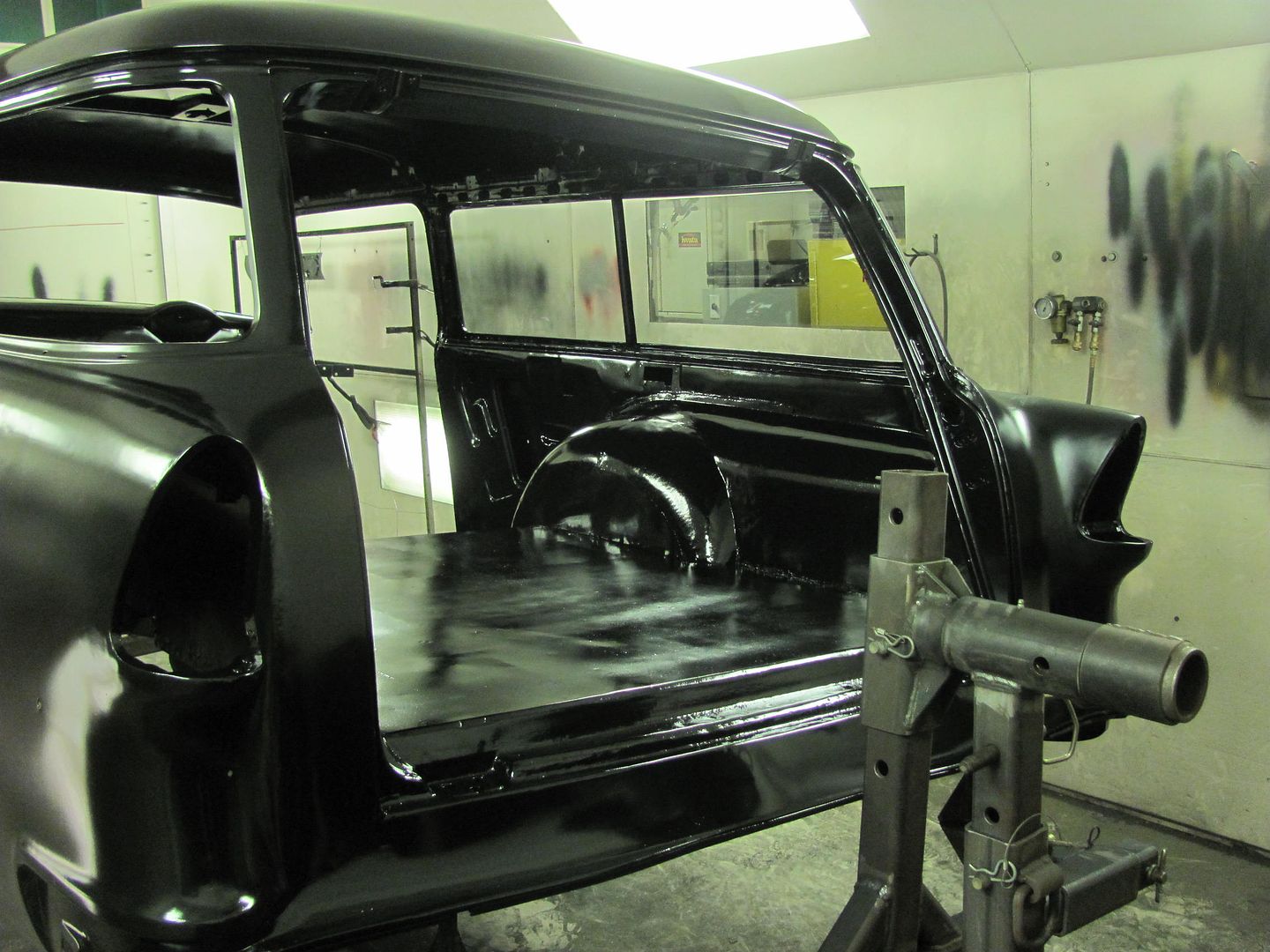
Real pleased with how well it turned out... here moved into the booth and the dehumidifier energized.
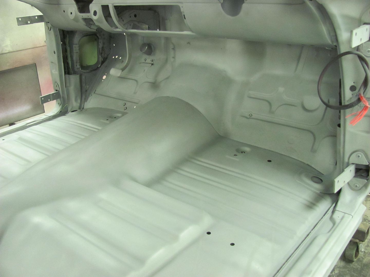
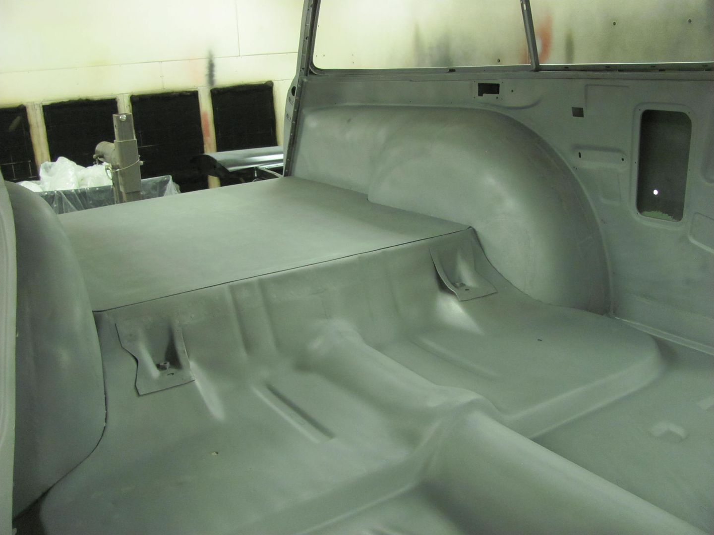
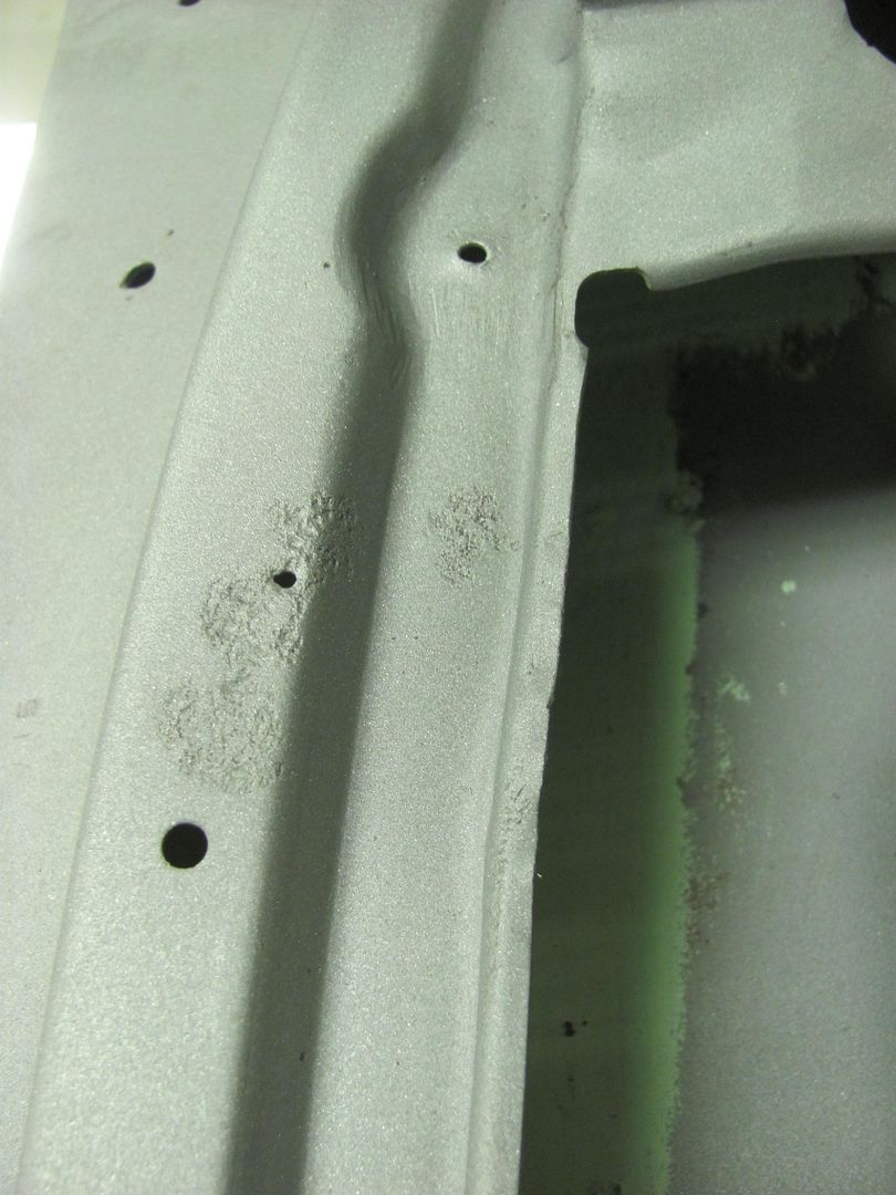
We do have some pin holes that are more apparent now, so we'll get those fixed Saturday morning and see how the weather looks for priming in the afternoon..
This is the part where you wish you had a tilt bed trailer so any media residue would be persuaded on out on the return trip home... But alas, we found a combination of using the air hose and a shop vac best to evacuate most of the media. That and about 50 or so revolutions on the rotisserie.....
Real pleased with how well it turned out... here moved into the booth and the dehumidifier energized.
We do have some pin holes that are more apparent now, so we'll get those fixed Saturday morning and see how the weather looks for priming in the afternoon..
MP&C
Member
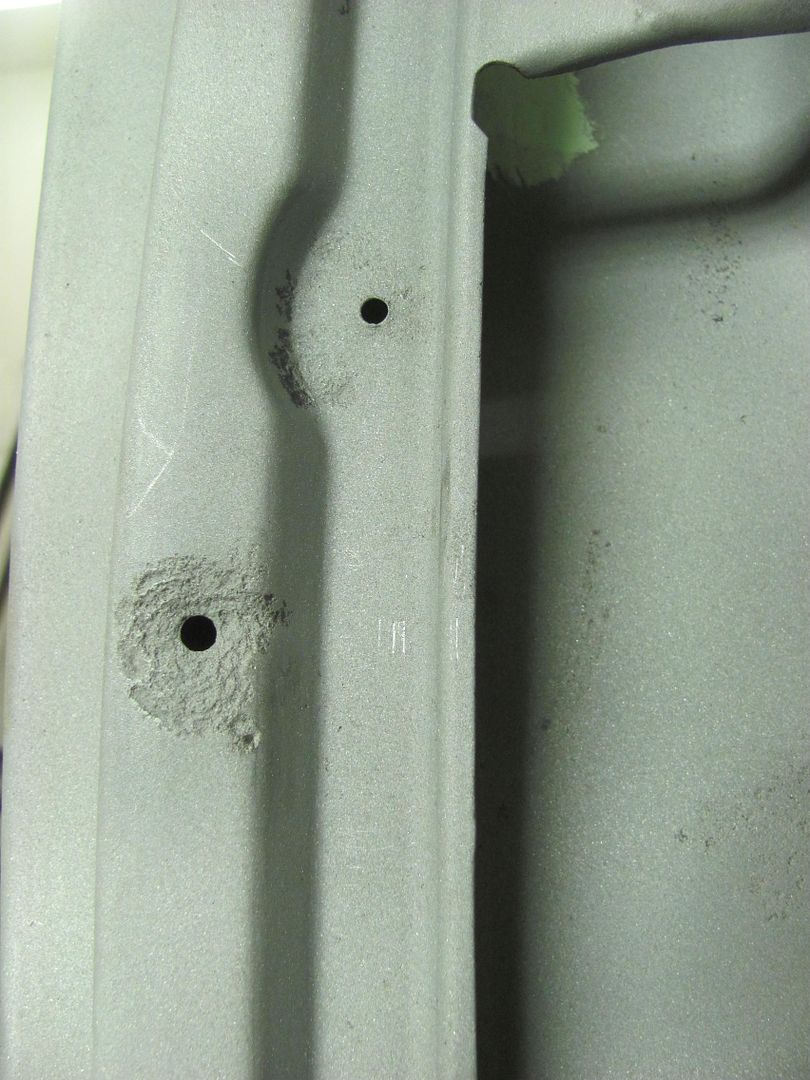
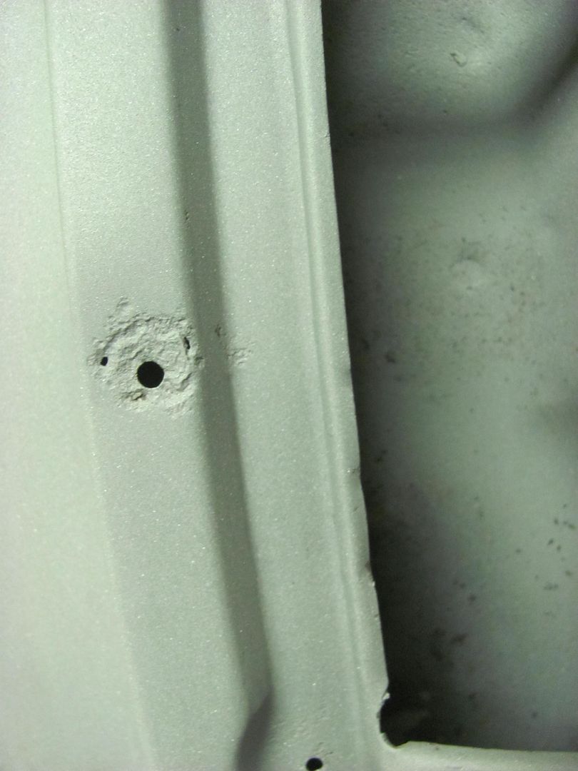
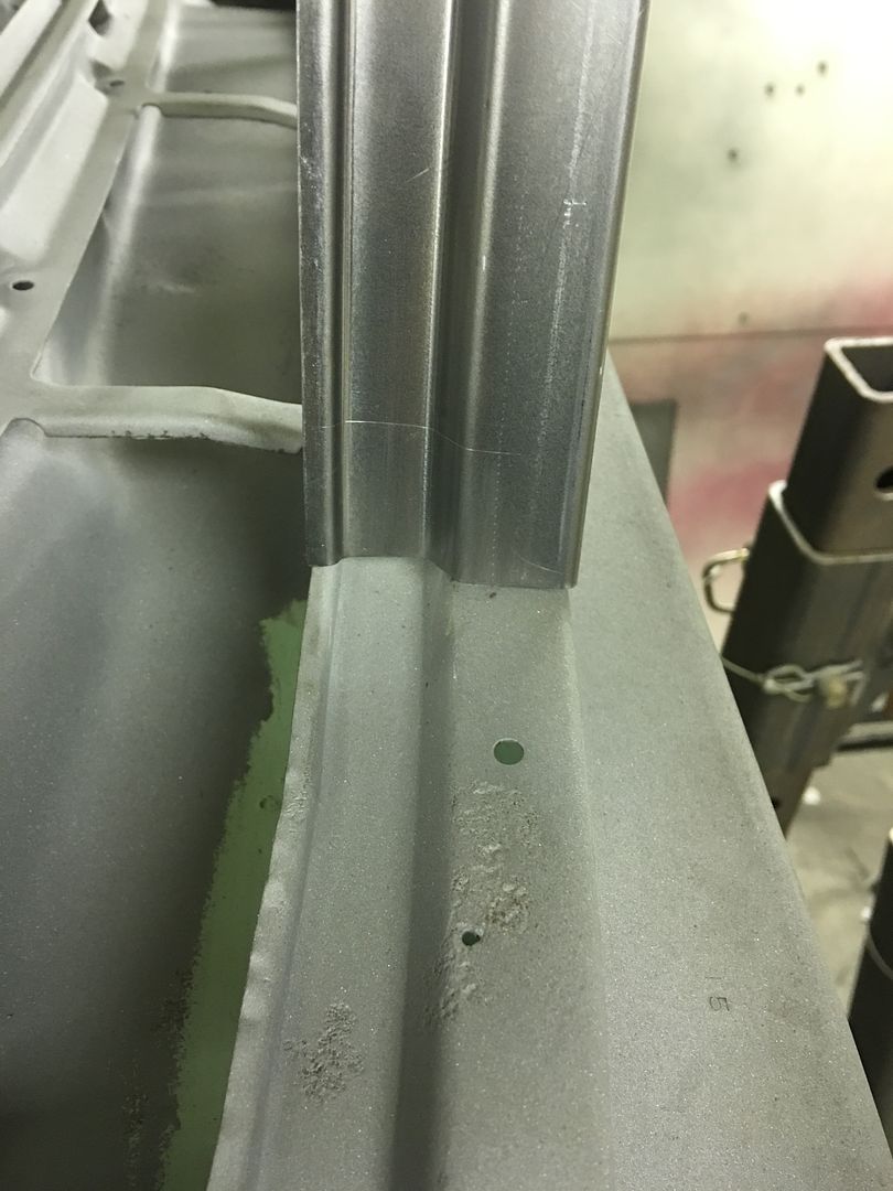
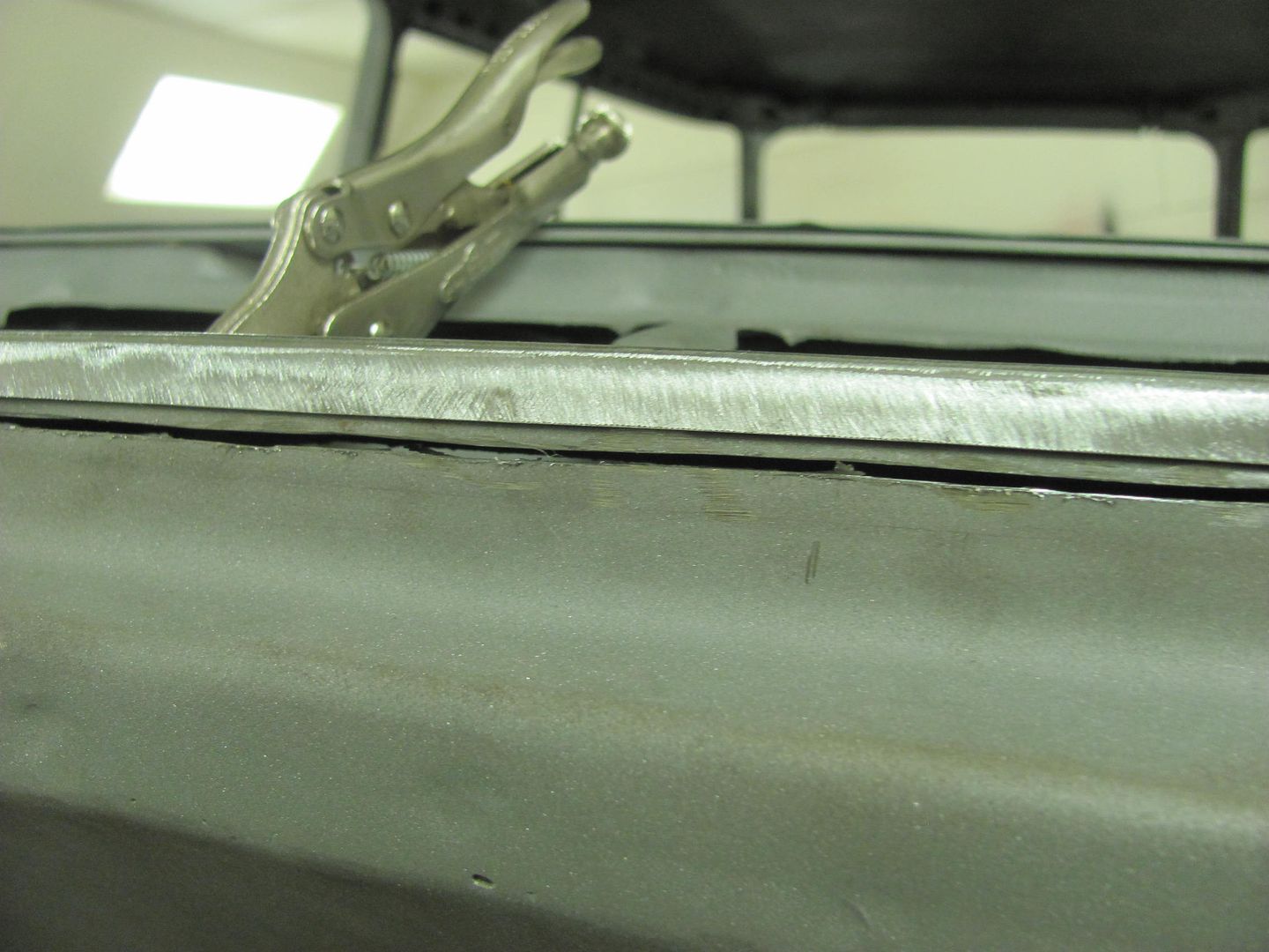
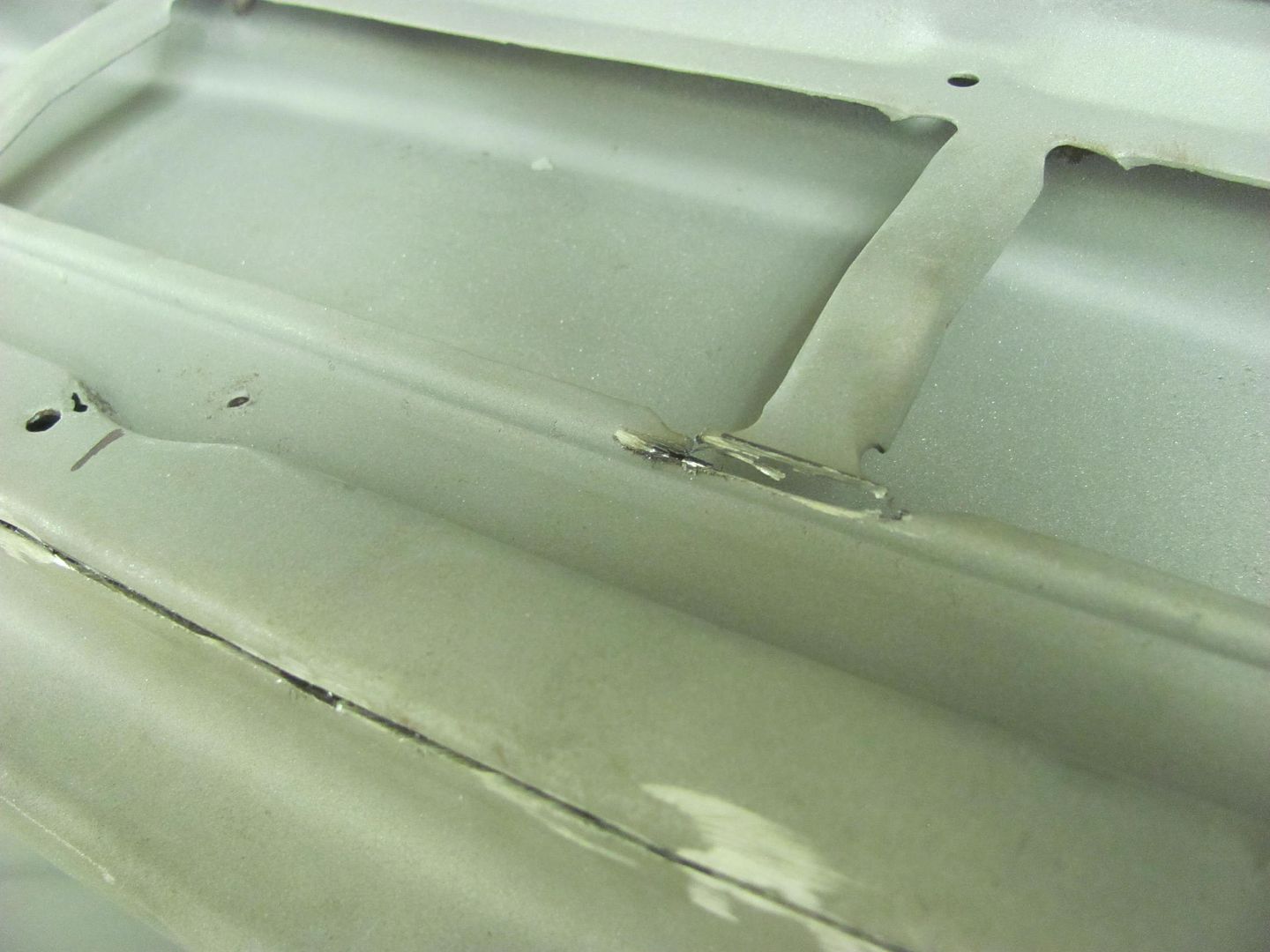
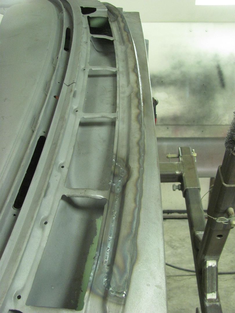
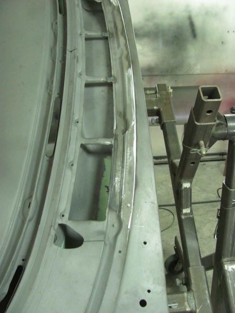
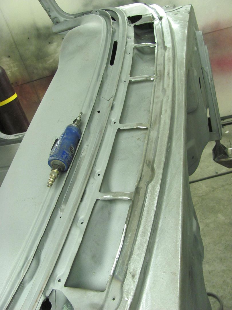
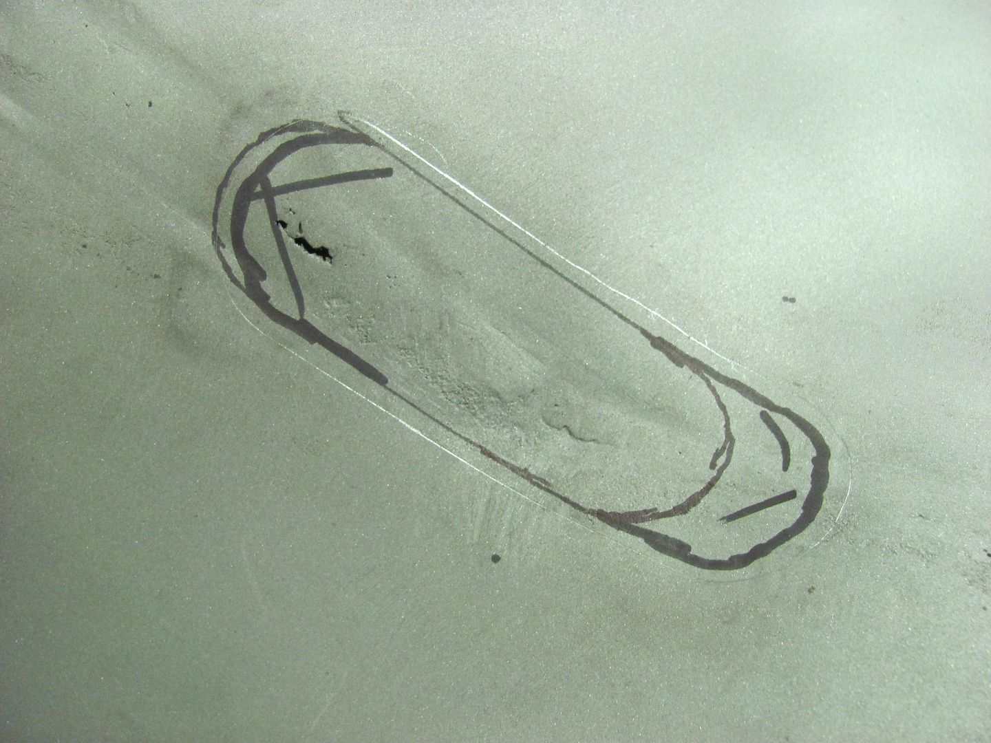
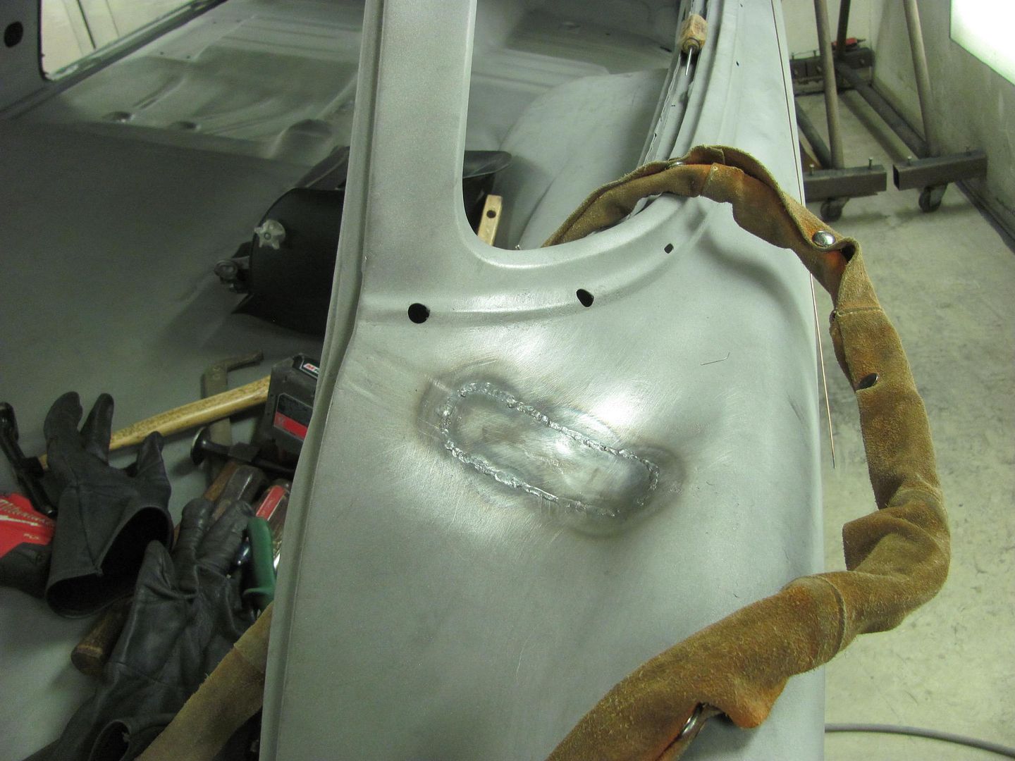
Well, no primer just yet, the media blasting showed the pitting at the cowl was a bit deeper than I thought.....
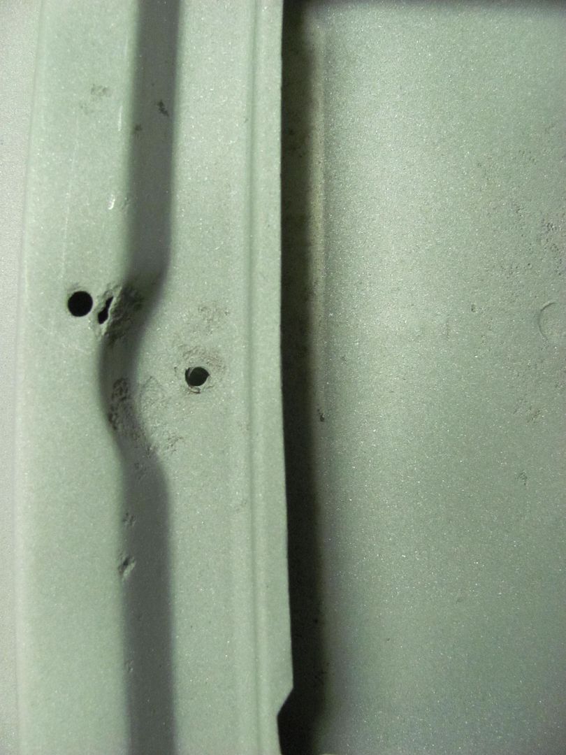
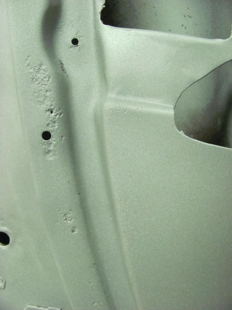
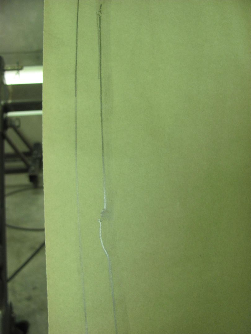
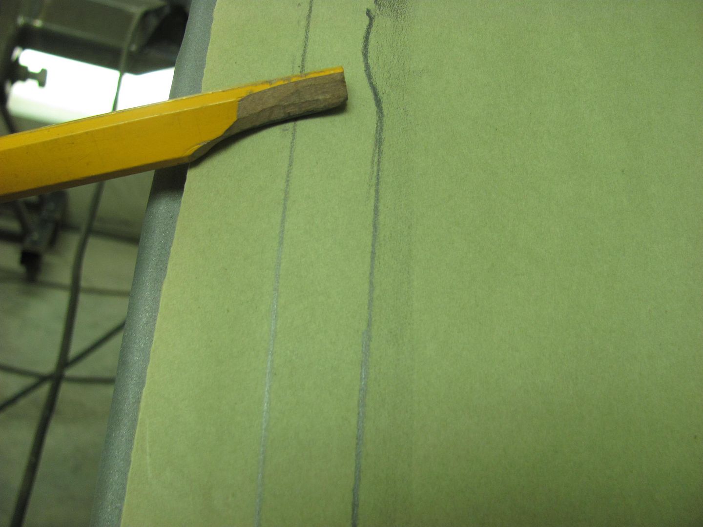
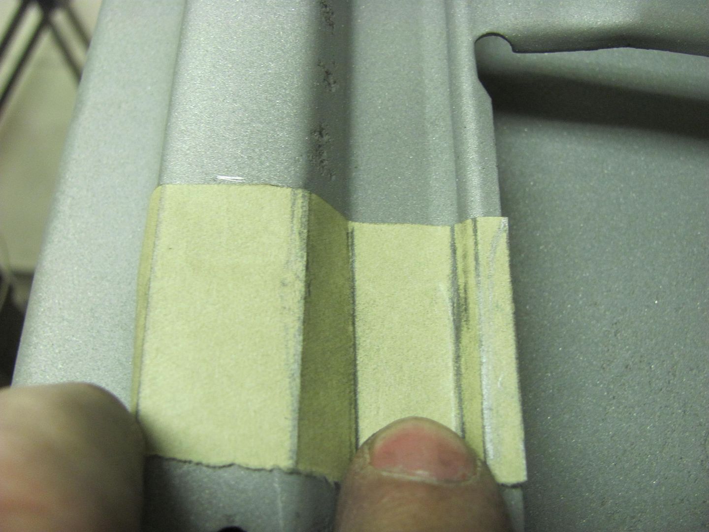
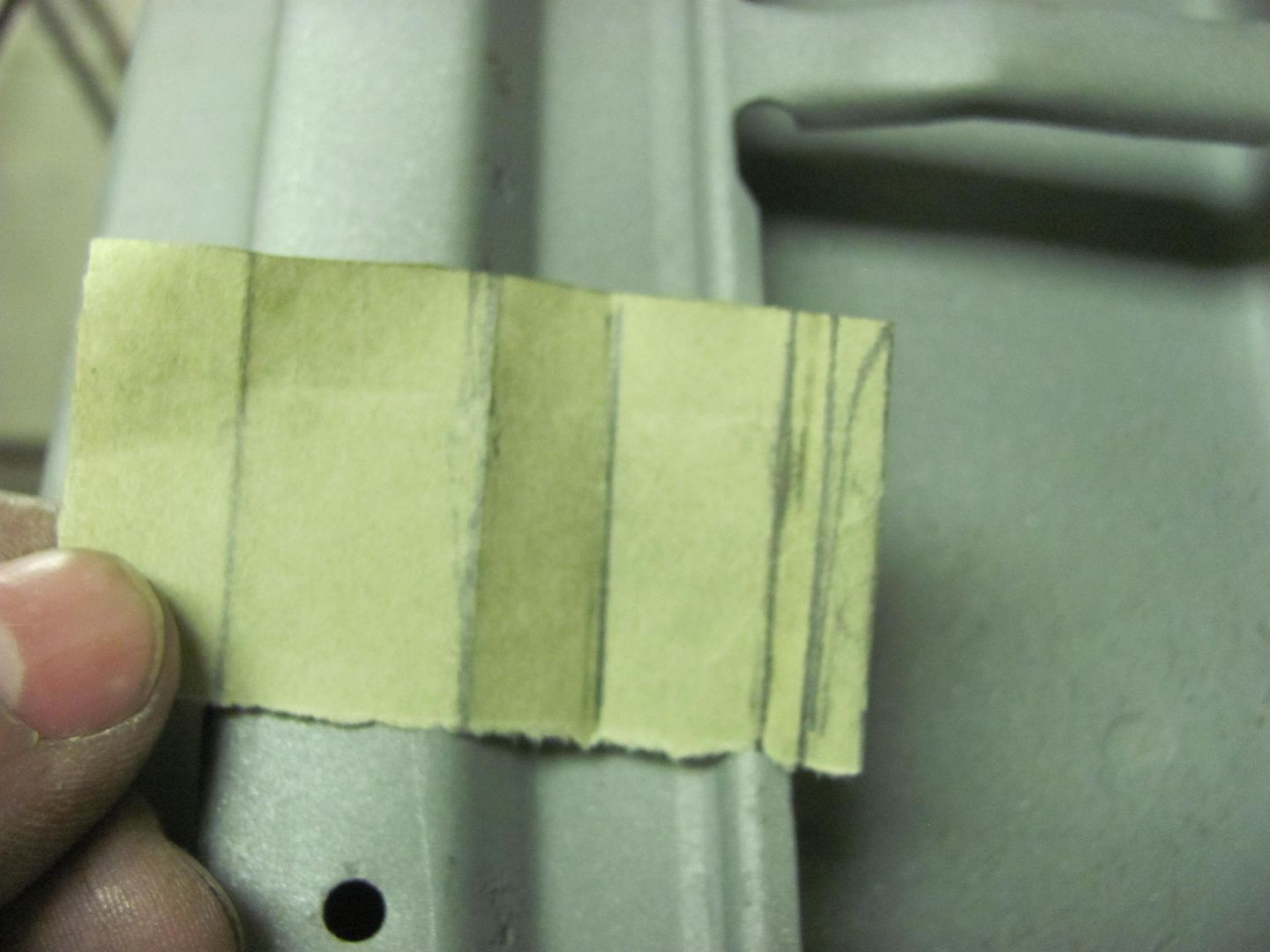
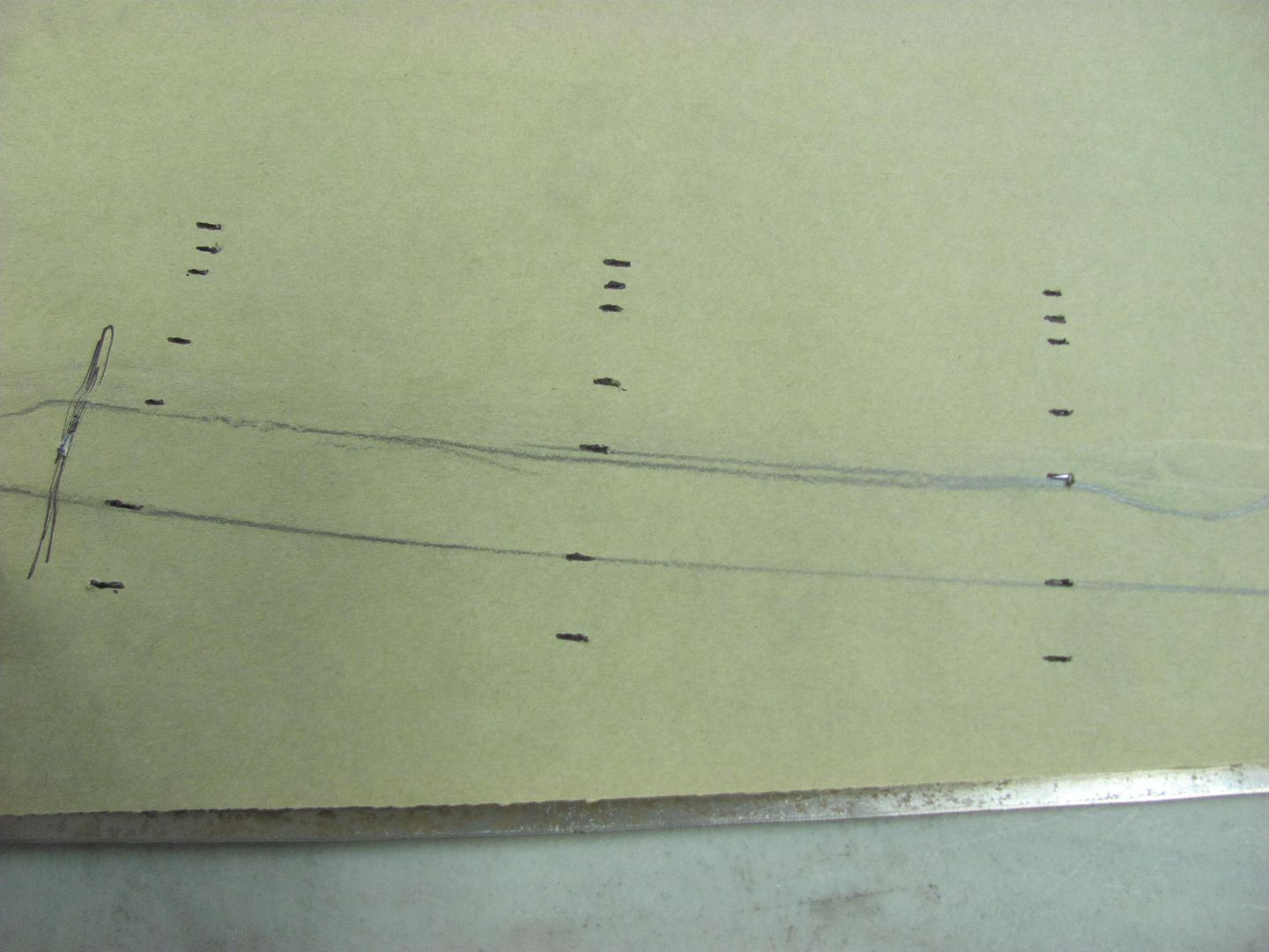
With so much widespread "issues", let's see if we can come close to duplicating this.. Taking a paper pattern..
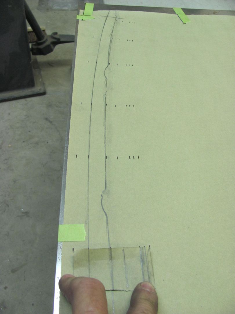
Here laid out on some 19 gauge AKDQ...
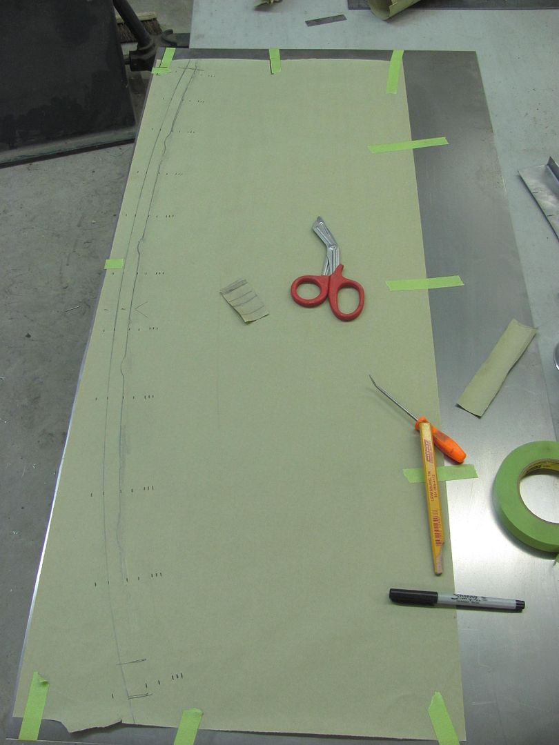
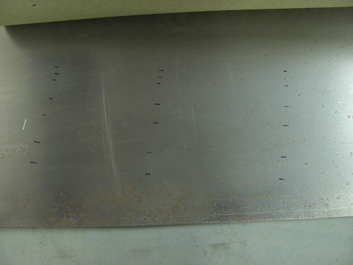
Trimming...
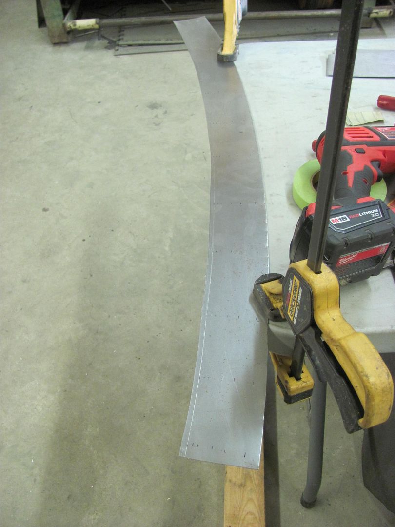
But I always prefer a test sample first... this done on the tipping wheel
Step dies on the Lennox add the final detail...
Need to fine tune the dimensions, but this looks close. I think I'll make up some dies for the Lennox for better consistency on the good piece..
With so much widespread "issues", let's see if we can come close to duplicating this.. Taking a paper pattern..
Here laid out on some 19 gauge AKDQ...
Trimming...
But I always prefer a test sample first... this done on the tipping wheel
Step dies on the Lennox add the final detail...
Need to fine tune the dimensions, but this looks close. I think I'll make up some dies for the Lennox for better consistency on the good piece..
MP&C
Member
Time to make some dies for the Lennox, here fine tuning the fit..
The outside corners will get some steel added for a sharper detail in the bends..
The 19 ga steel is a good snug fit for the band saw cuts...
The front edge of the panel will be tipped prior to running it through the Lennox, the tipped flange will act as a guide in the slot in the lower die..
Another test run using a straight piece of scrap
Dimensions looking much better.
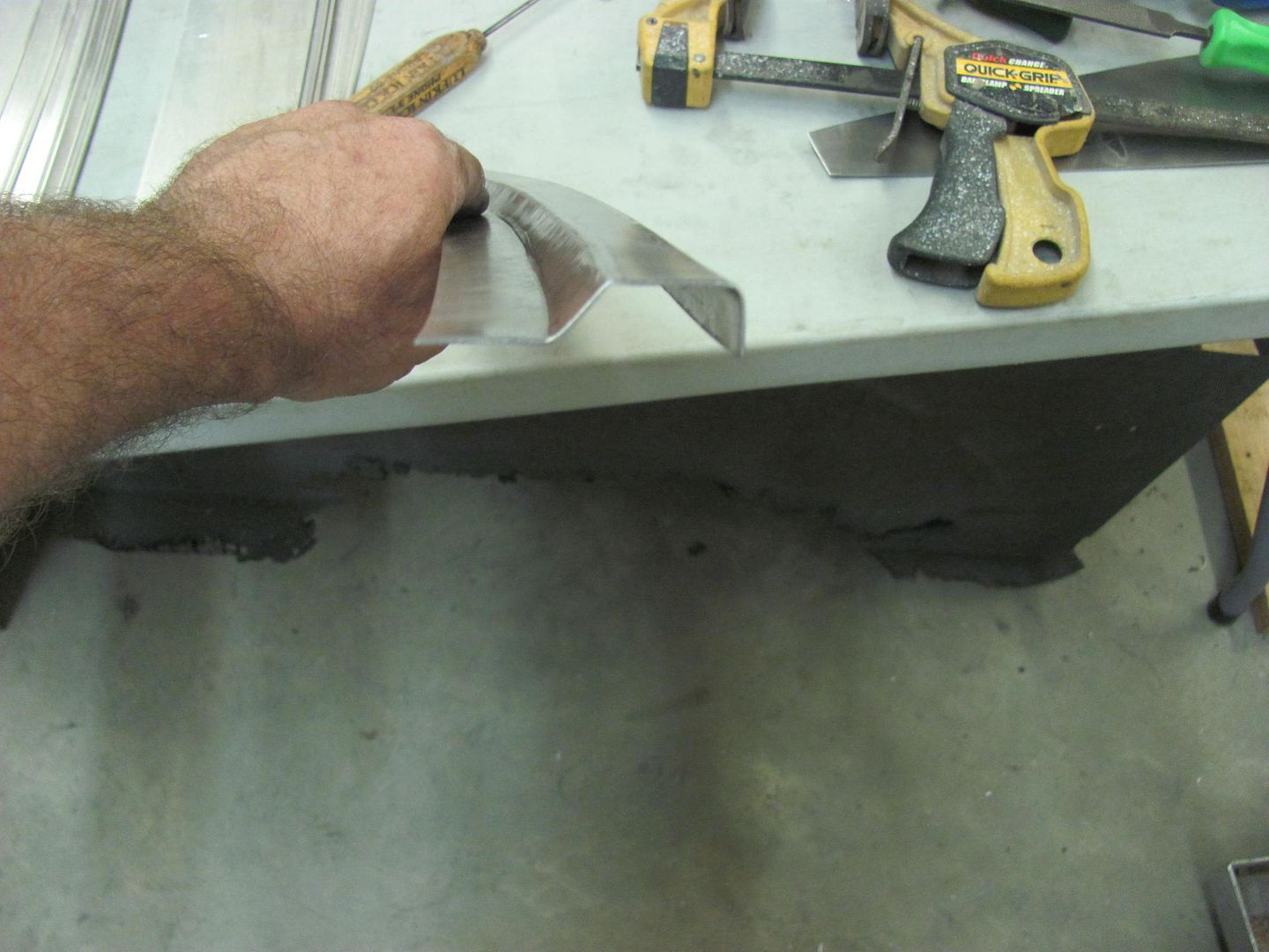
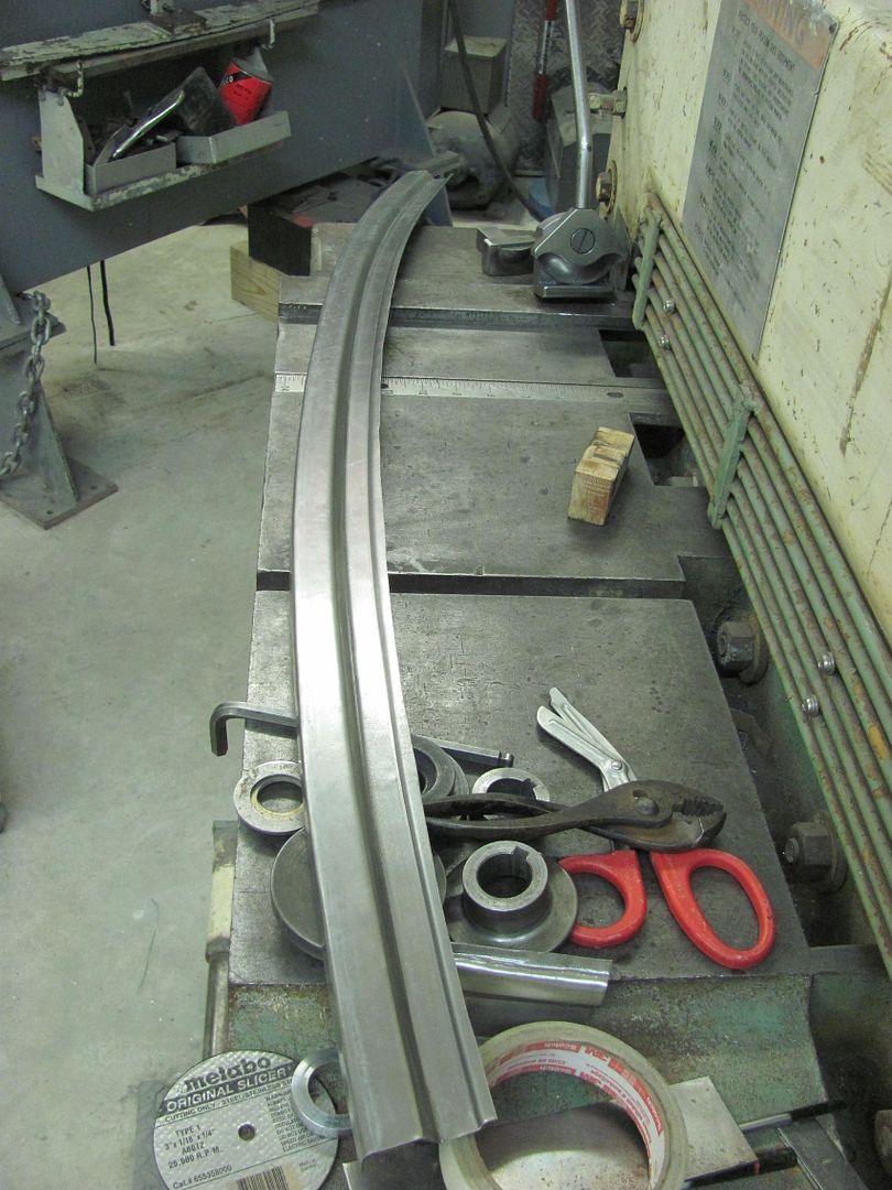
Enough practice, starting to tip the flange on the good piece.. The tipping wheel on the bead roller bends about 30 degrees and the remaining is done manually with the hand tipping tool..
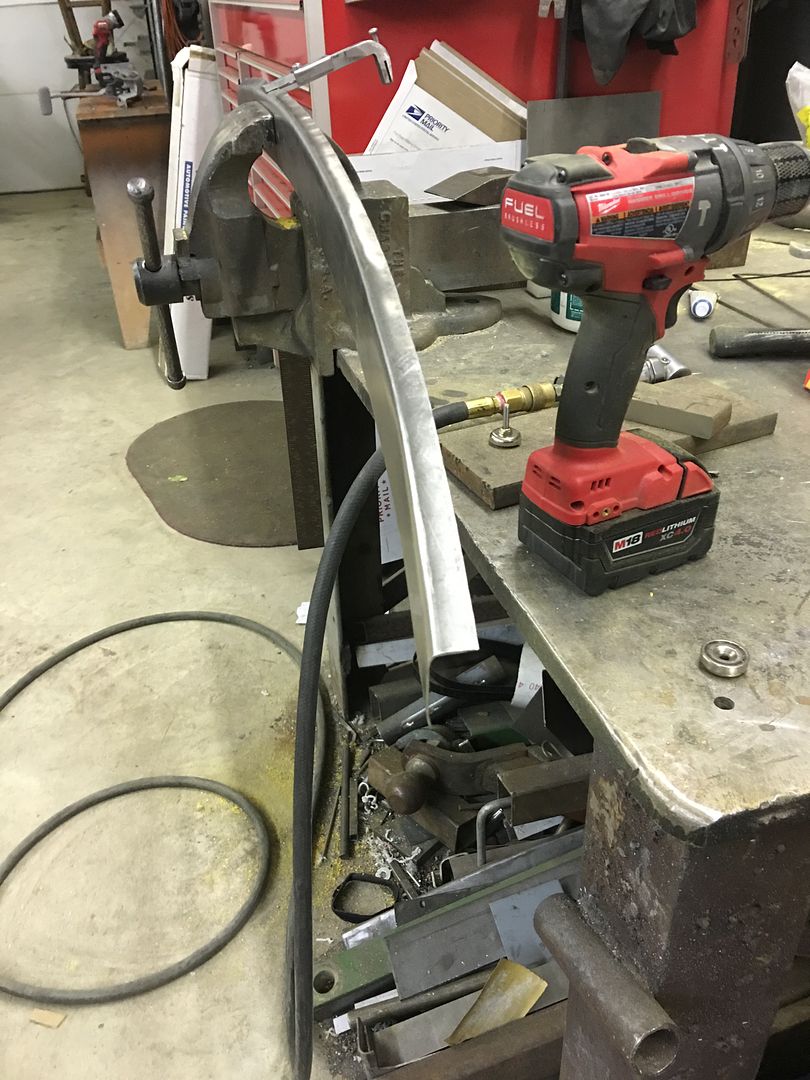
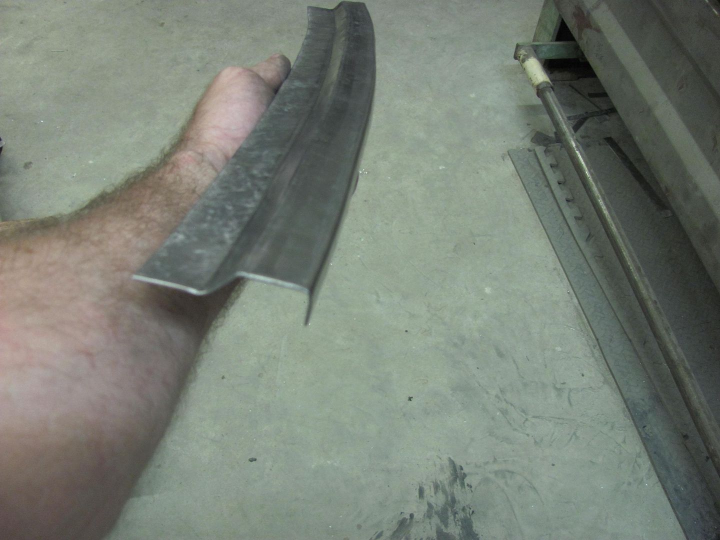
Flange tipped, some kick shrinking to get the right contour, and we're about ready for the Lennox.. As Kyle was off tonight we'll wait until he returns so we can have two people feeding this long piece through the machine..
The outside corners will get some steel added for a sharper detail in the bends..
The 19 ga steel is a good snug fit for the band saw cuts...
The front edge of the panel will be tipped prior to running it through the Lennox, the tipped flange will act as a guide in the slot in the lower die..
Another test run using a straight piece of scrap
Dimensions looking much better.
Enough practice, starting to tip the flange on the good piece.. The tipping wheel on the bead roller bends about 30 degrees and the remaining is done manually with the hand tipping tool..
Flange tipped, some kick shrinking to get the right contour, and we're about ready for the Lennox.. As Kyle was off tonight we'll wait until he returns so we can have two people feeding this long piece through the machine..
MP&C
Member
As we found with some of the practice pieces, when you try to shove metal too much into a hole it tends to pull in from the edges.
So to fix that we'll make up a new bottom die to form the ramp fold fully, then change back to the above die to form the step..
The down side to using phenolic is that it gives a bit where it doesn't make sharp creases well or short reverse folds either. The initial practice pieces wouldn't fold the step down flat, so a wrap of steel was added to the top die to better persuade the step flat...
The upper die holder helps keep the wrapped steel in place.
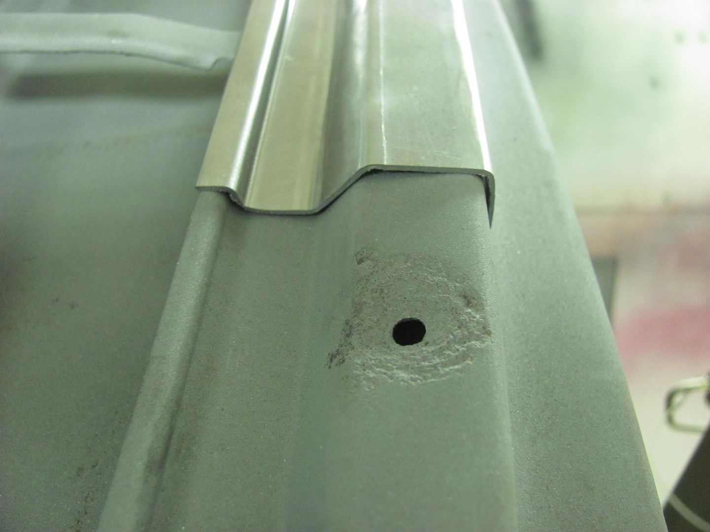
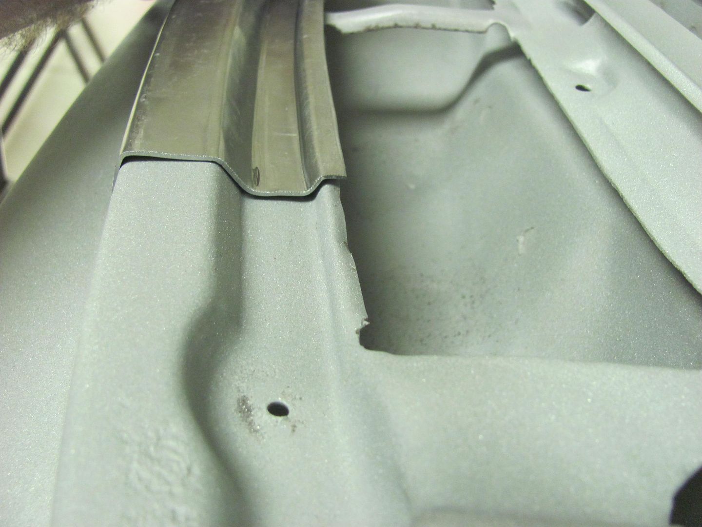
That did the trick, step is laying down nice and flat..
The front flange hangs over just a bit too much, some hammer action will bring it back in place. Real pleased with how well this turned out..
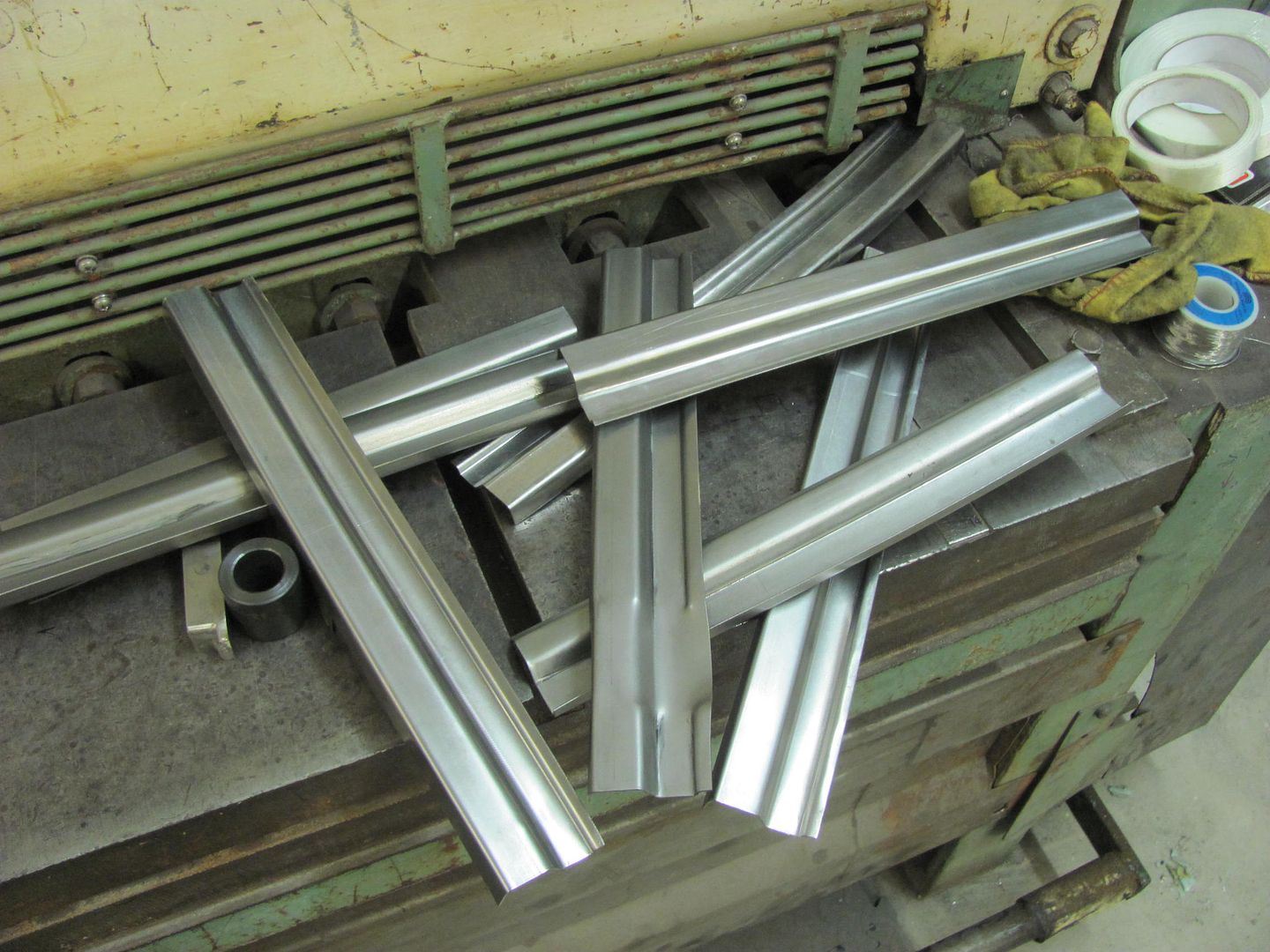
Some of the practice scraps..
So to fix that we'll make up a new bottom die to form the ramp fold fully, then change back to the above die to form the step..
The down side to using phenolic is that it gives a bit where it doesn't make sharp creases well or short reverse folds either. The initial practice pieces wouldn't fold the step down flat, so a wrap of steel was added to the top die to better persuade the step flat...
The upper die holder helps keep the wrapped steel in place.
That did the trick, step is laying down nice and flat..
The front flange hangs over just a bit too much, some hammer action will bring it back in place. Real pleased with how well this turned out..
Some of the practice scraps..
MP&C
Member
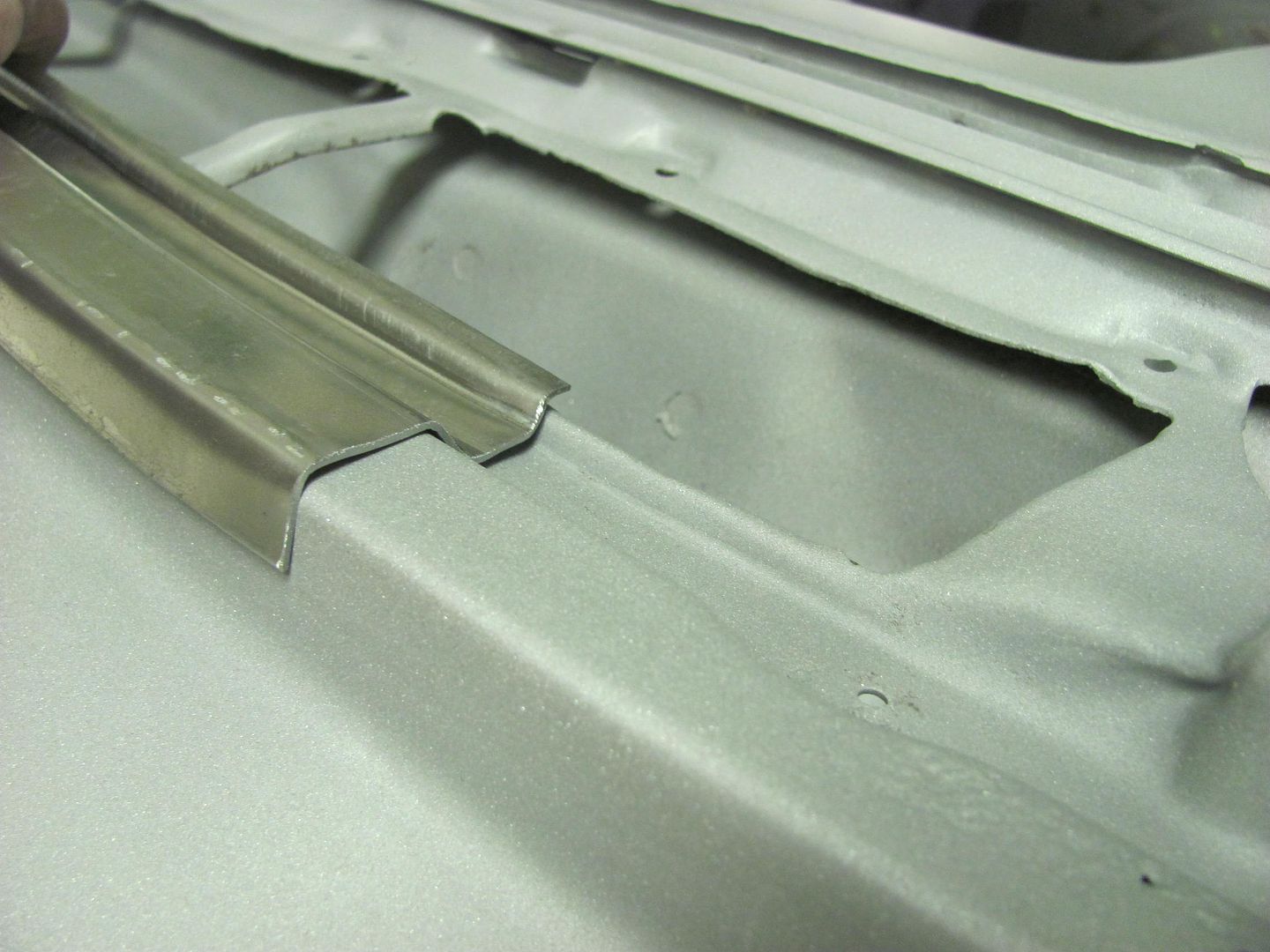
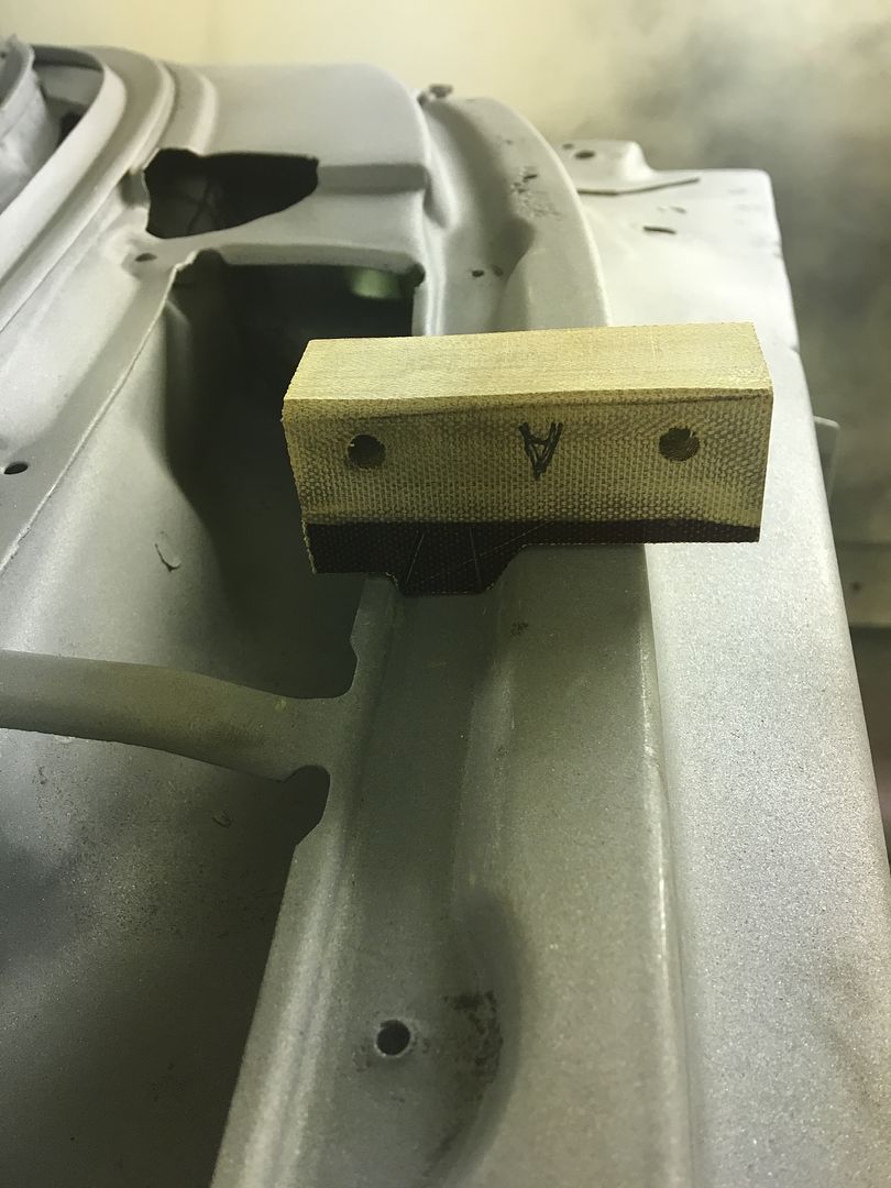
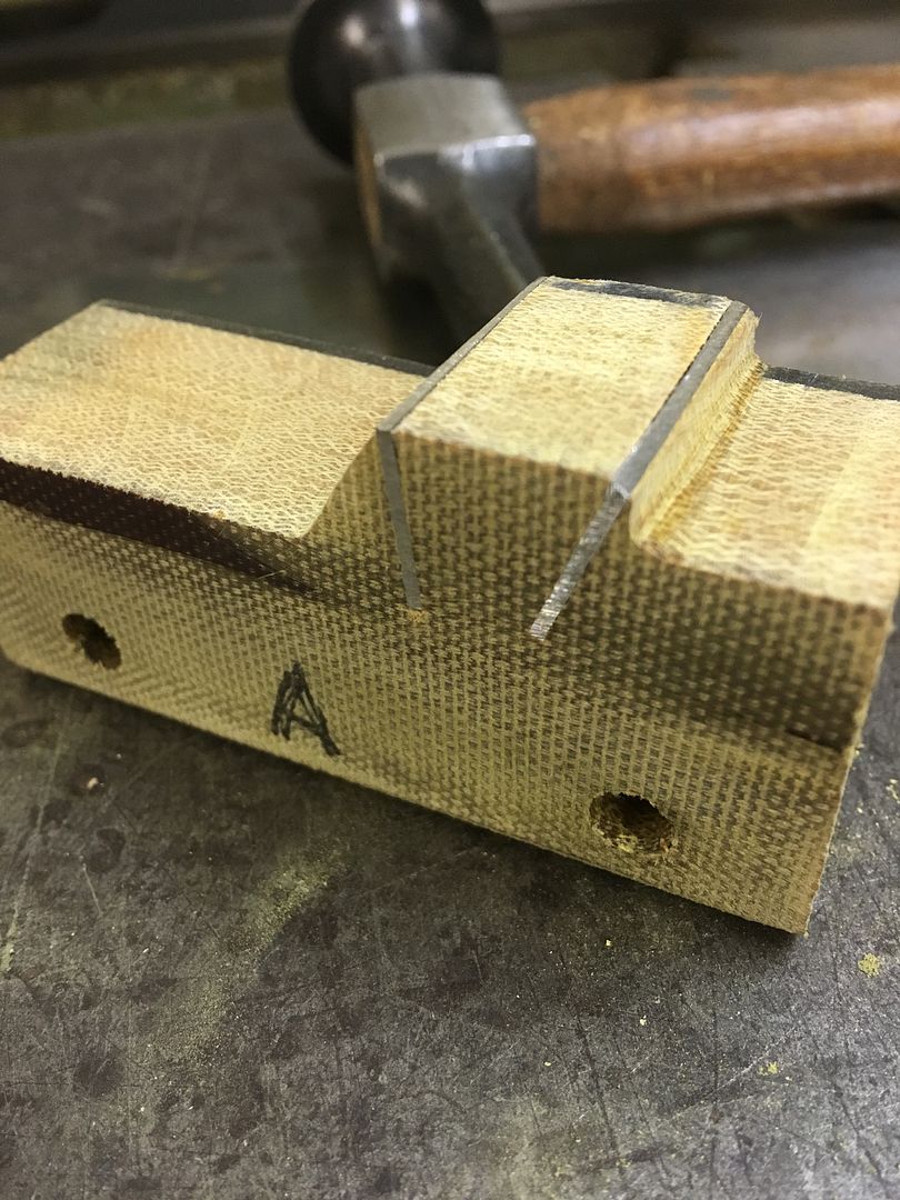
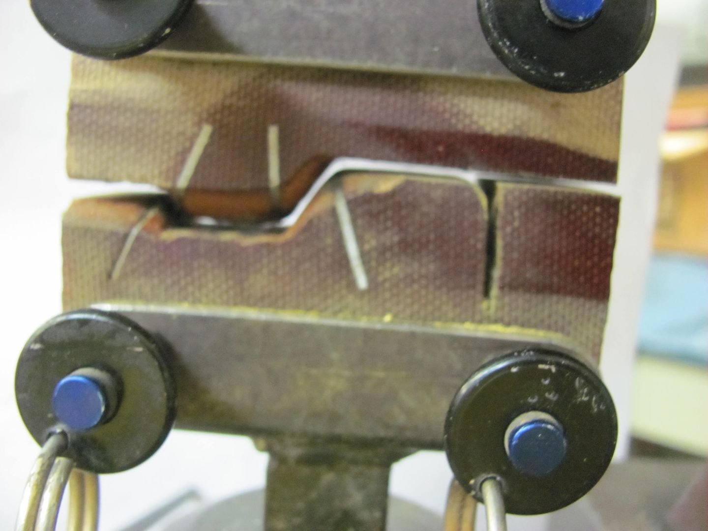
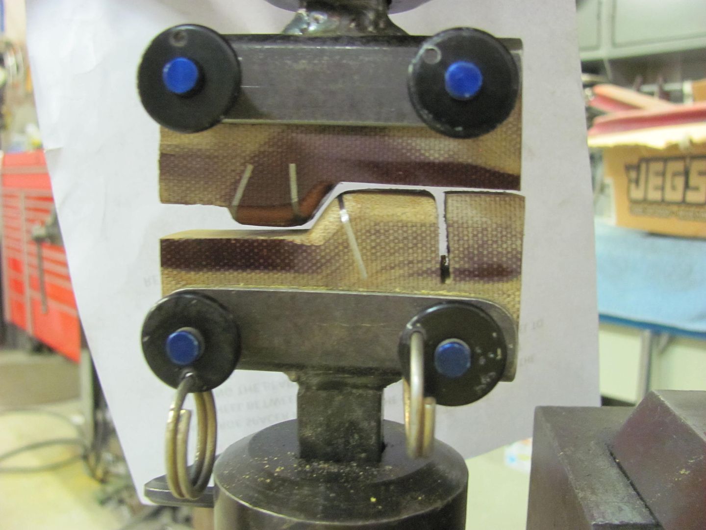
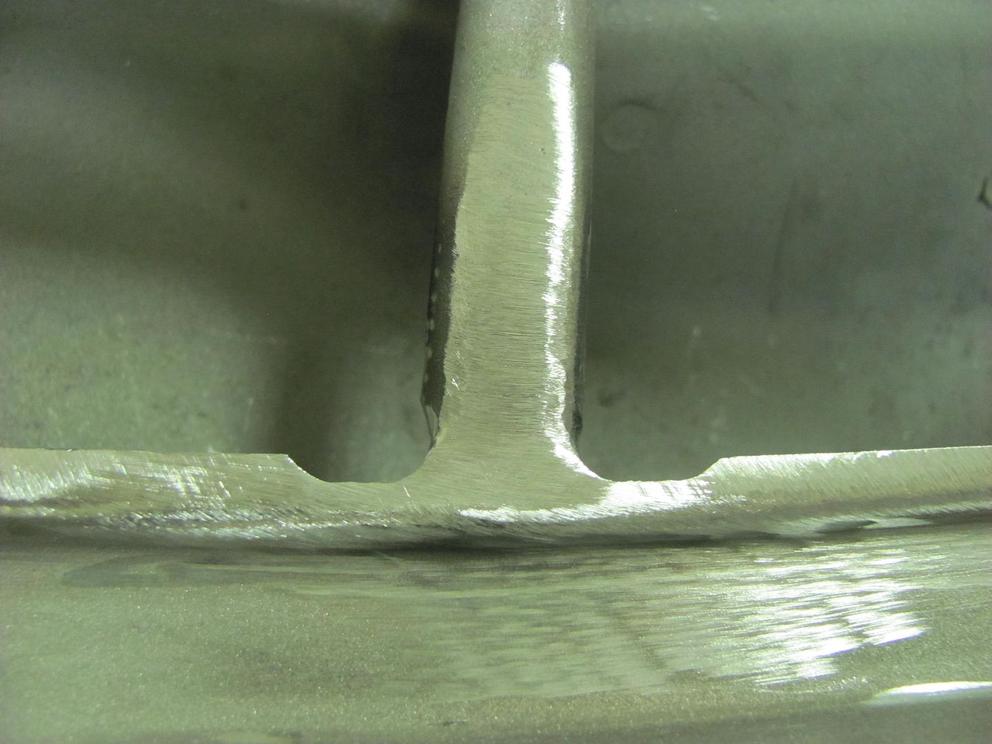
Next task on the list is to add the semi-circular relief areas into the new cowl repair panel..
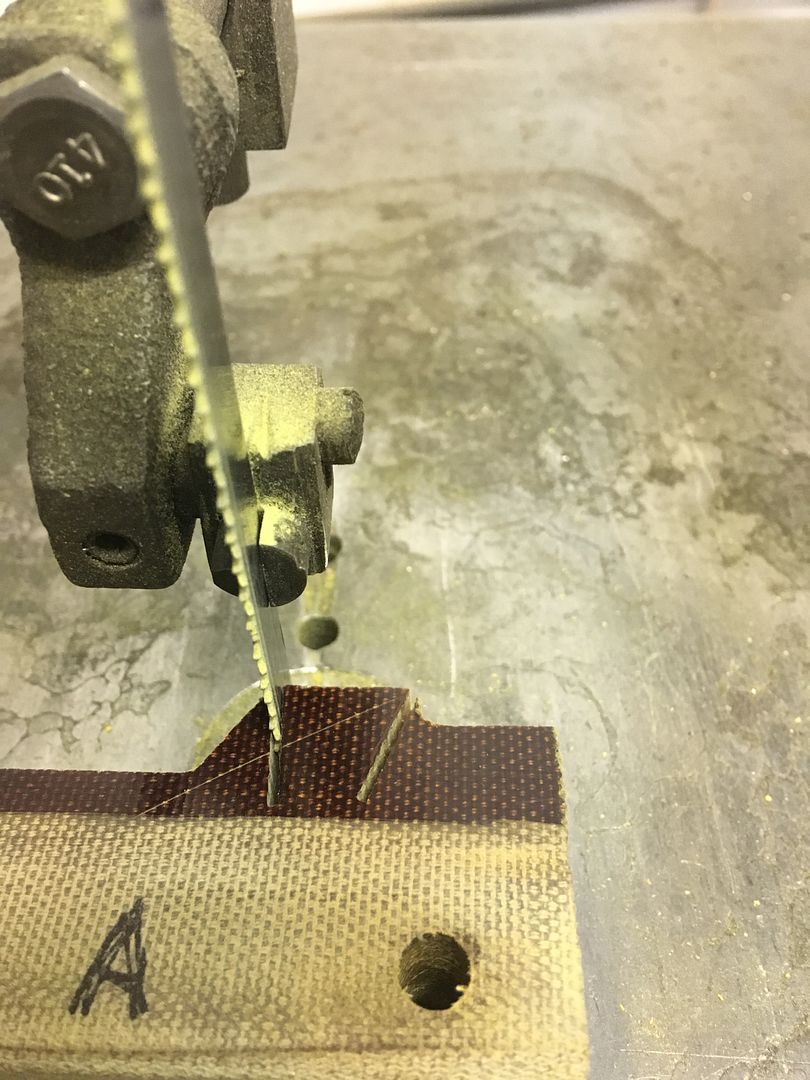
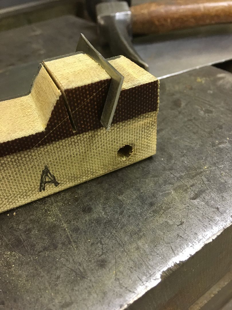
A suitable piece of Phenolic is cut out, notched at the bottom for "vise support", and used a roloc sander and drum sander to add the relief area in the "hammer form".
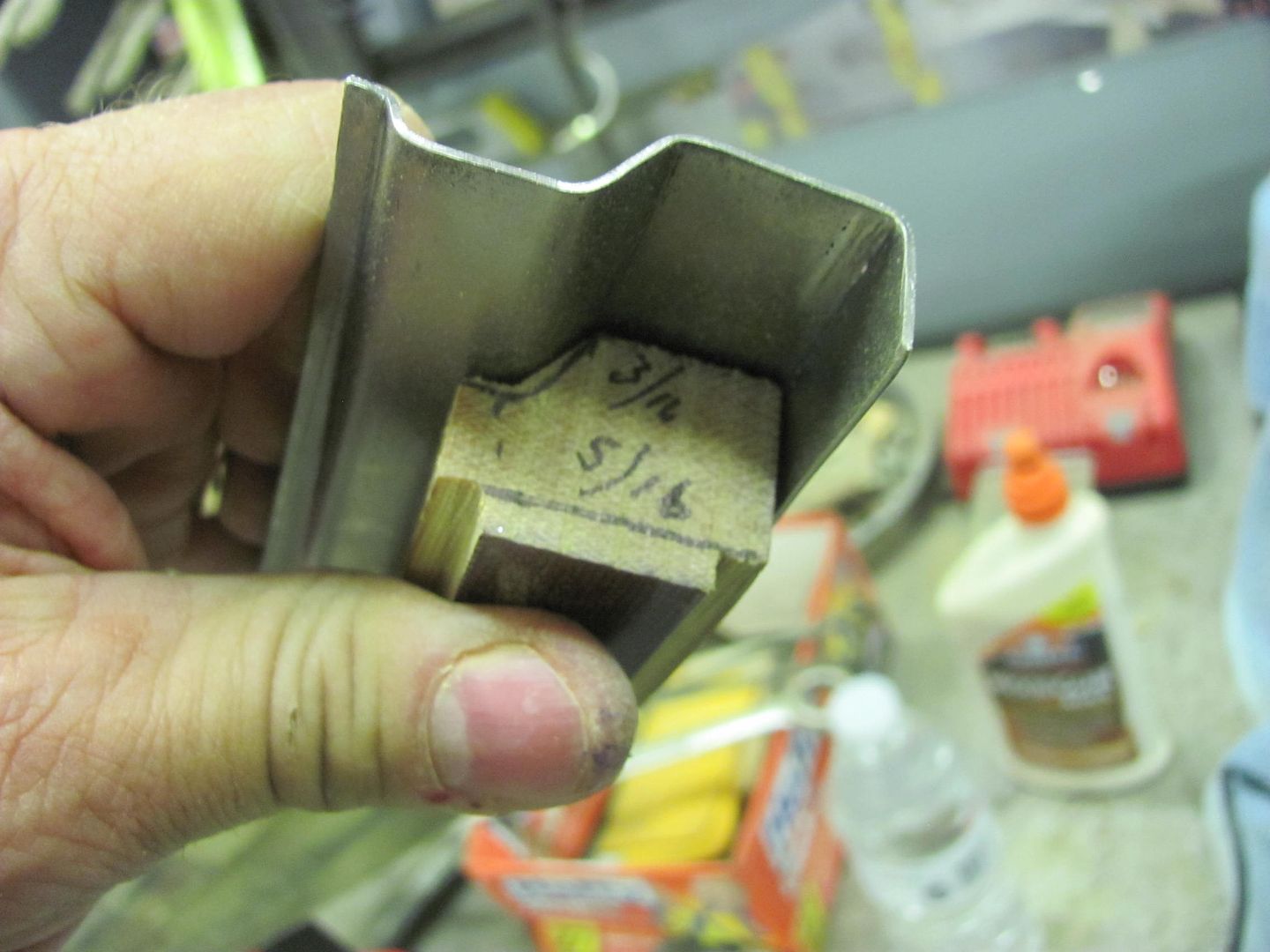
Here's the Vise support shown in action... should remain nice and stable through all the hammer action..
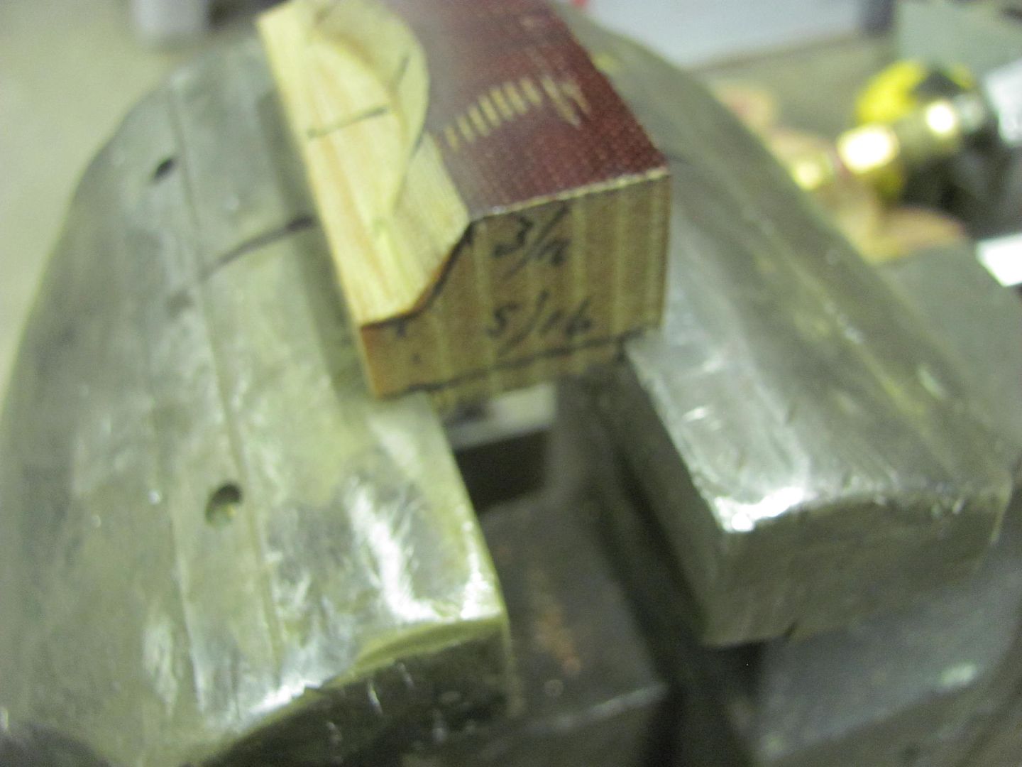
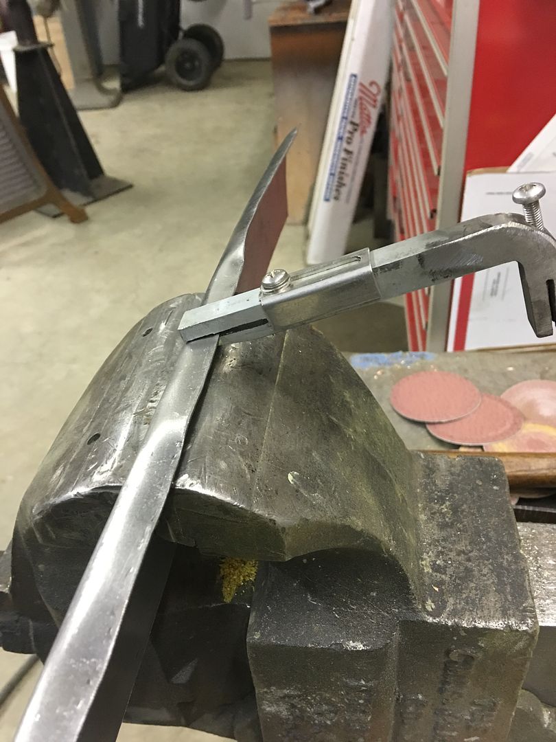
Centerline of the hammerform marked, as well as on the vise, to better align our new cowl..
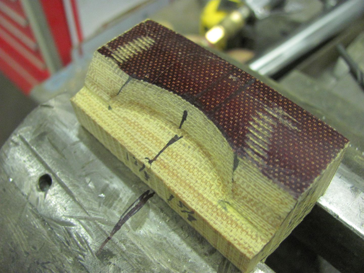
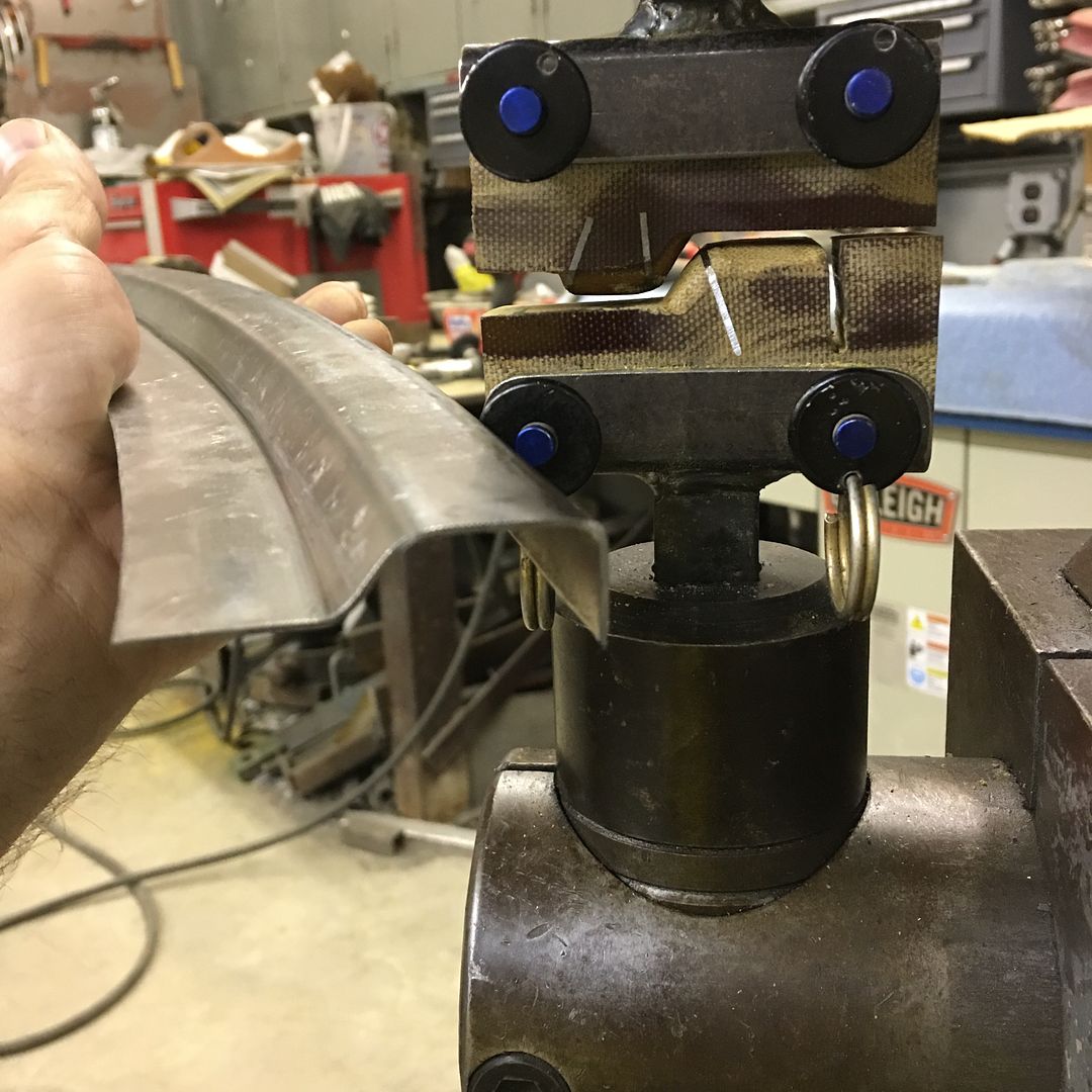
Door skin hammer will be used here to provide the radius, this one was touched up as the factory radius was a bit too large.
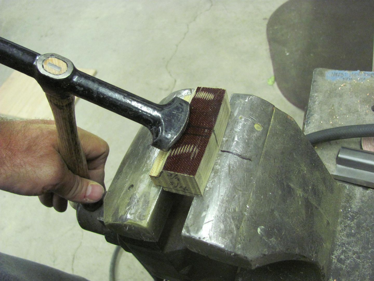
Tried it on one of our scrap pieces first..
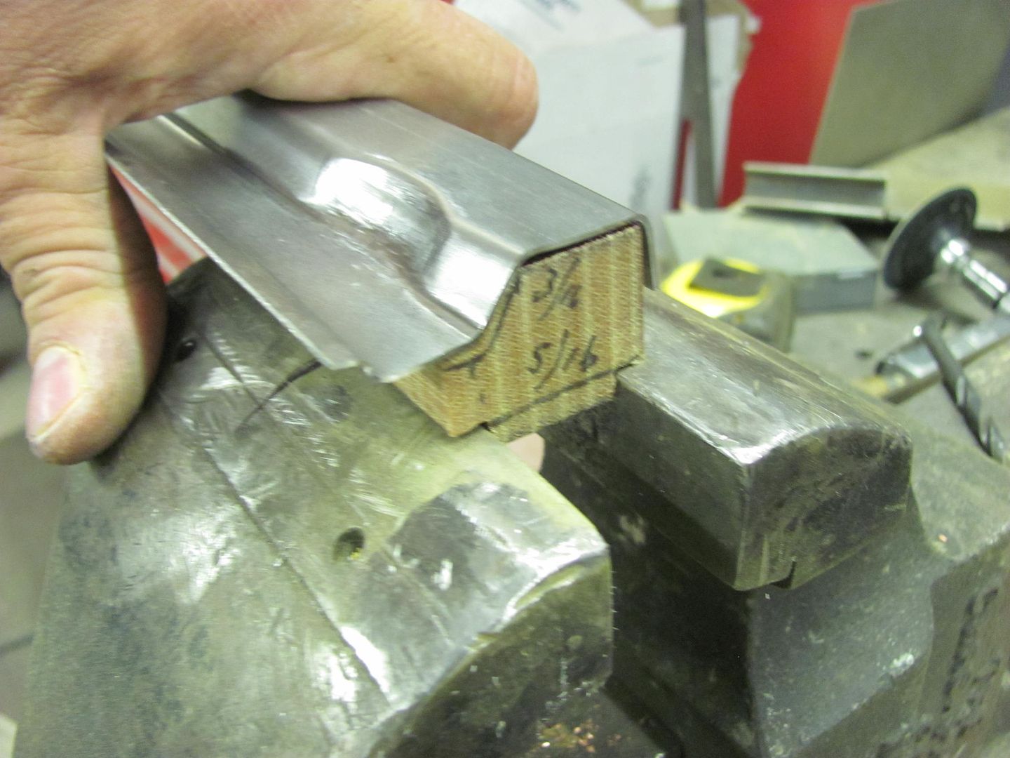
Back side..
Front side and comparison to the factory version
Action video showing the process:
https://www.youtube.com/watch?v=3TawUVtIl5w
A suitable piece of Phenolic is cut out, notched at the bottom for "vise support", and used a roloc sander and drum sander to add the relief area in the "hammer form".
Here's the Vise support shown in action... should remain nice and stable through all the hammer action..
Centerline of the hammerform marked, as well as on the vise, to better align our new cowl..
Door skin hammer will be used here to provide the radius, this one was touched up as the factory radius was a bit too large.
Tried it on one of our scrap pieces first..
Back side..
Front side and comparison to the factory version
Action video showing the process:
https://www.youtube.com/watch?v=3TawUVtIl5w
MP&C
Member
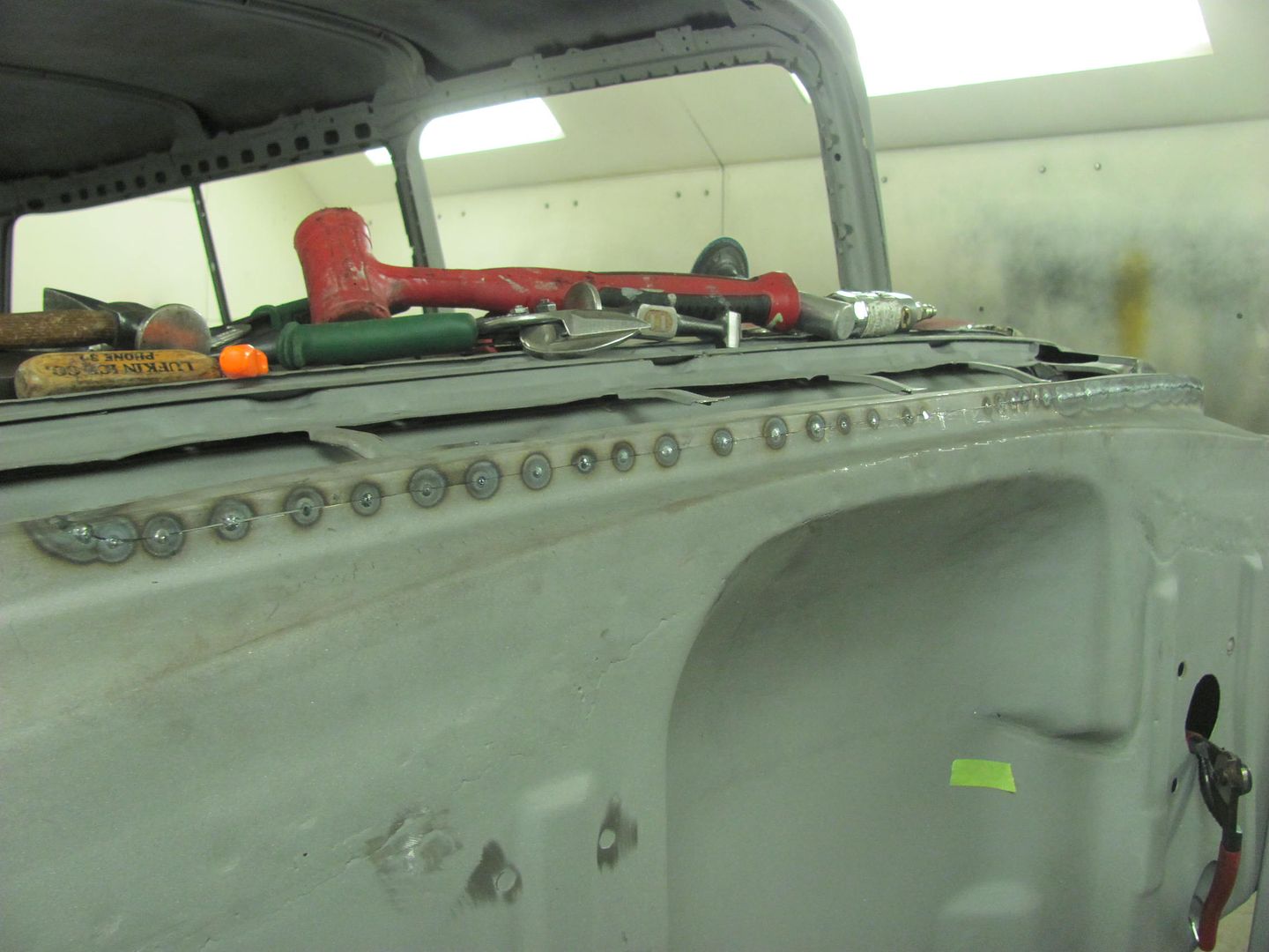
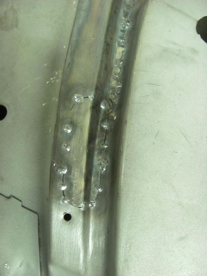
OK, it's been a while since I've TIG welded, and got a little too much heat near the edge. Blew a nice hole, so used one of the practice pieces to cut out a patch..
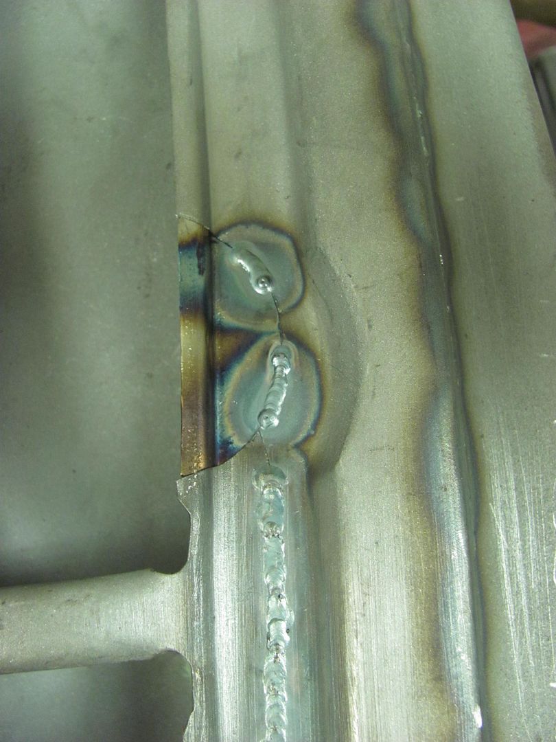
.....and I got a little heavy footed on the other end as well...
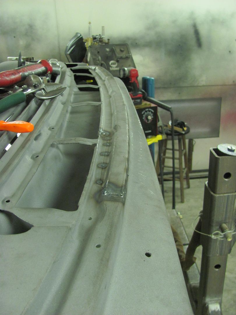
Trimming for the patch's patch.
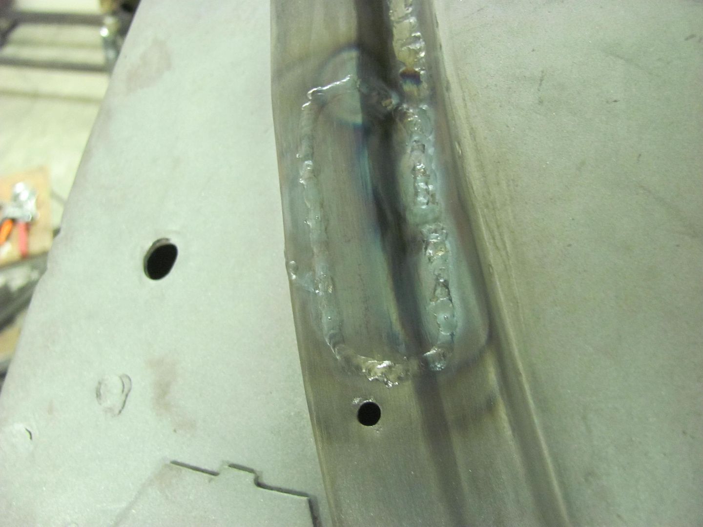
The final pieces to weld...
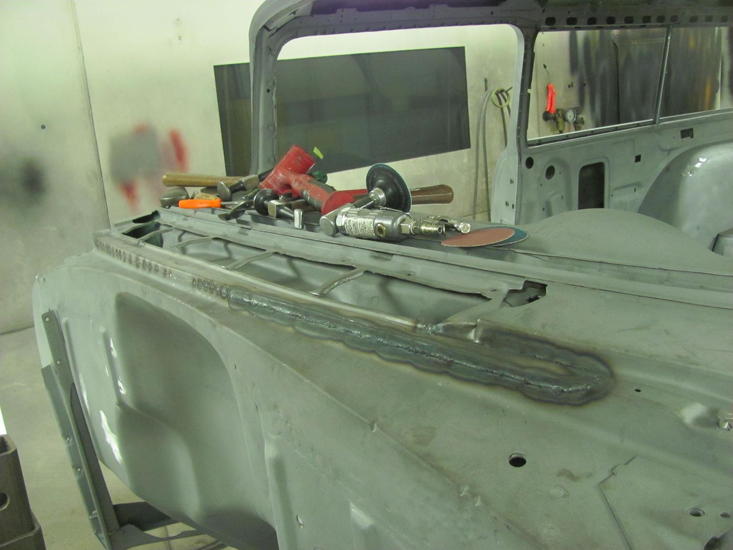
Weld dressed and factory relief added...
A few more welds to dress and this will be done...
.....and I got a little heavy footed on the other end as well...
Trimming for the patch's patch.
The final pieces to weld...
Weld dressed and factory relief added...
A few more welds to dress and this will be done...
MP&C
Member
Thanks!
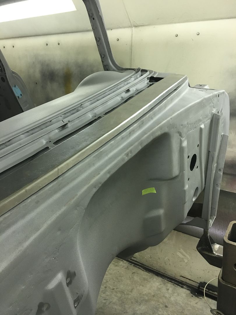
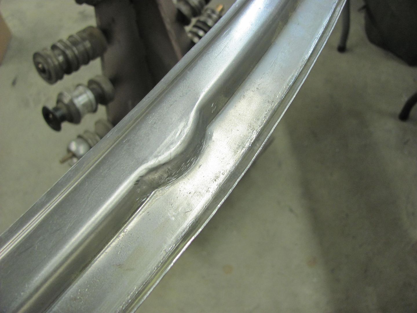
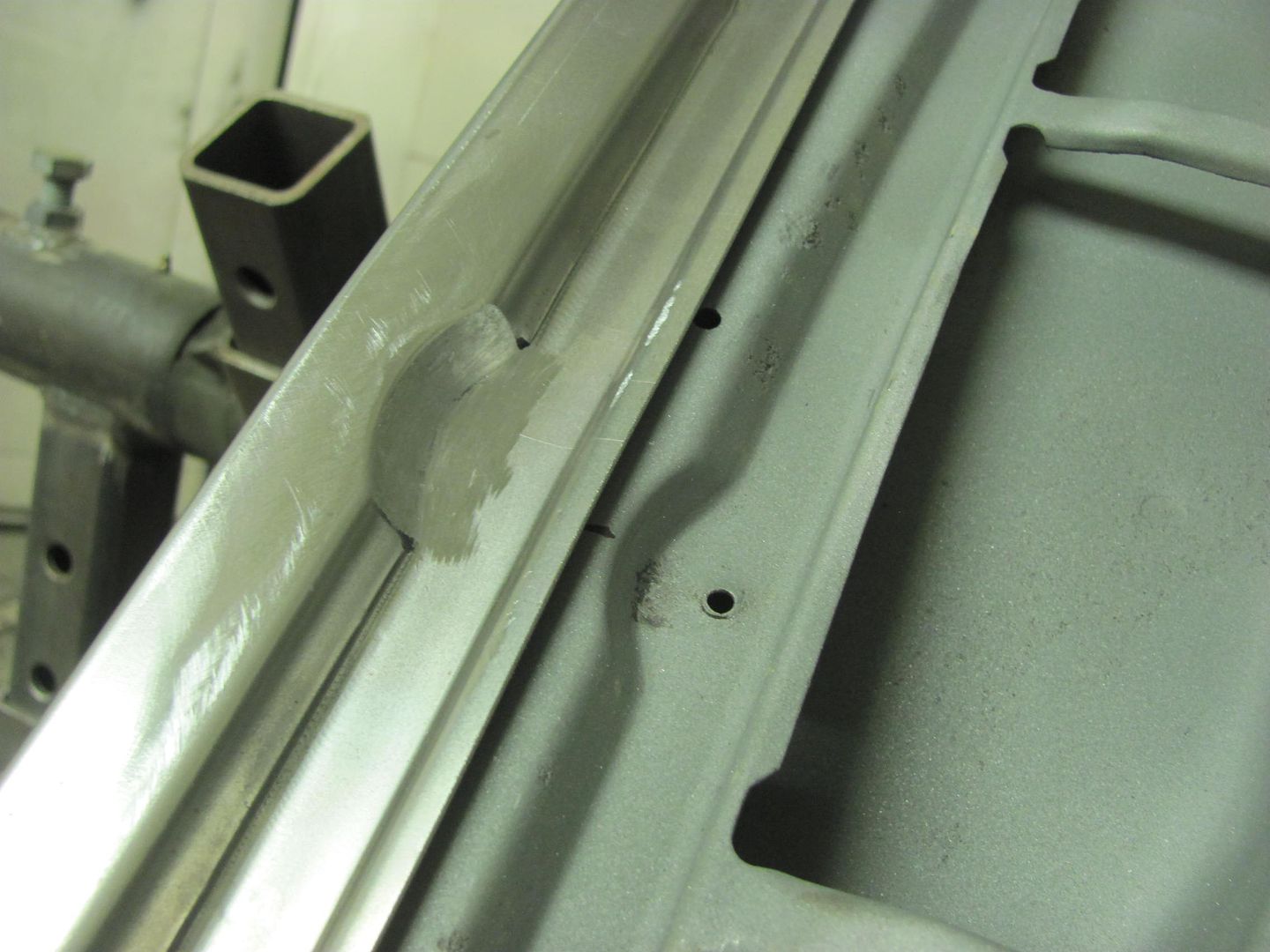
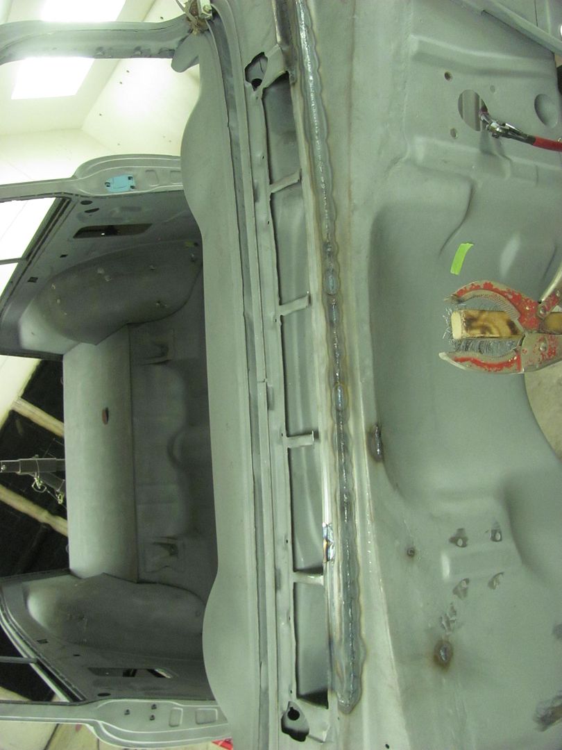
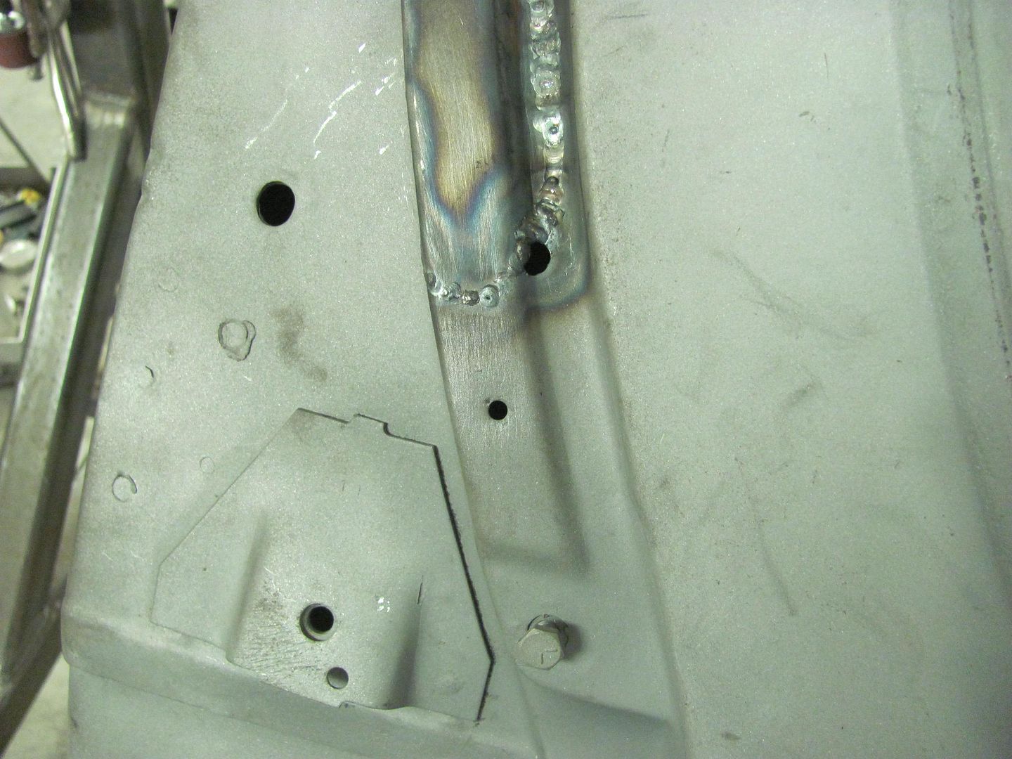
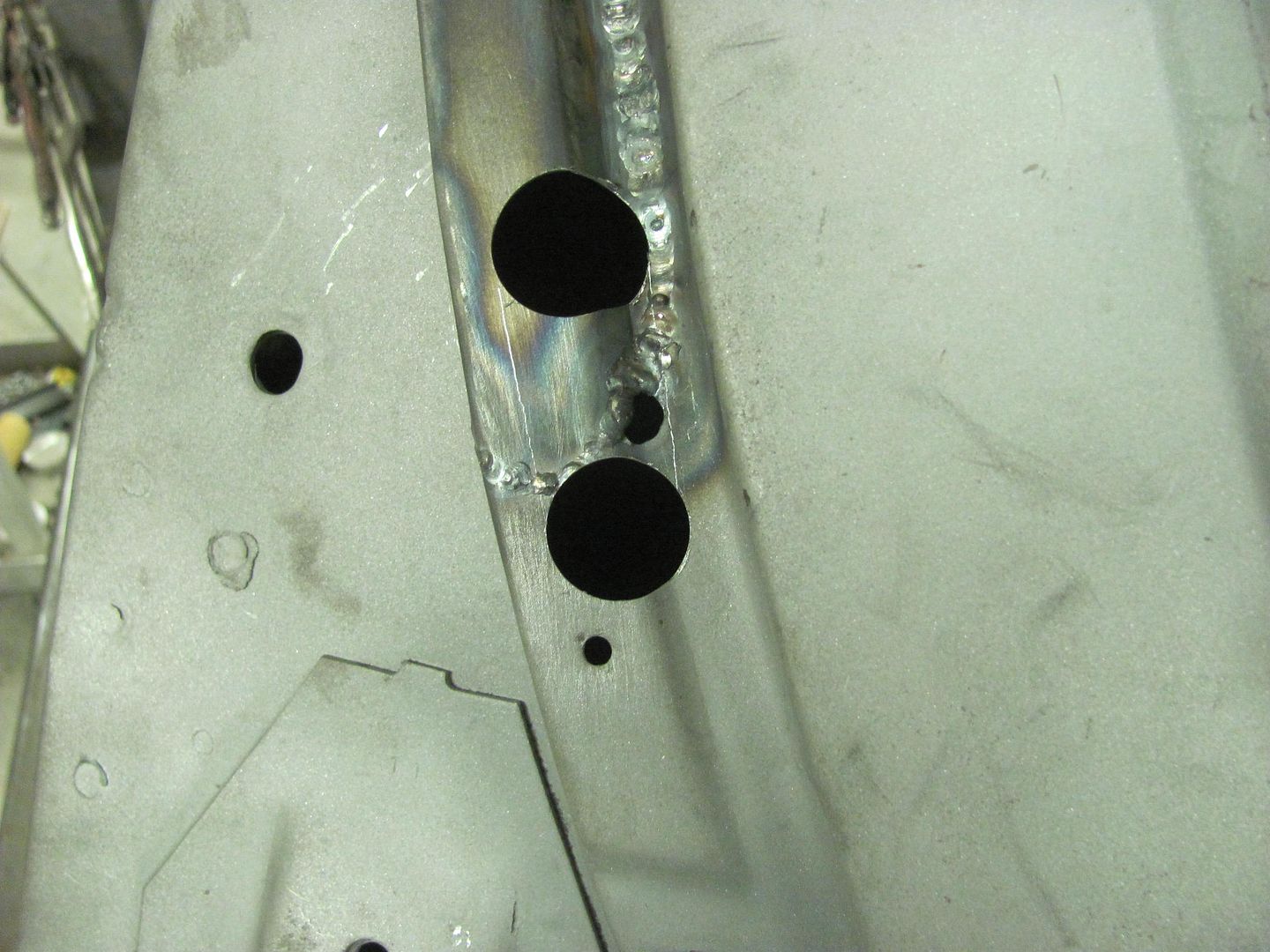
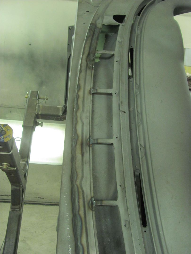
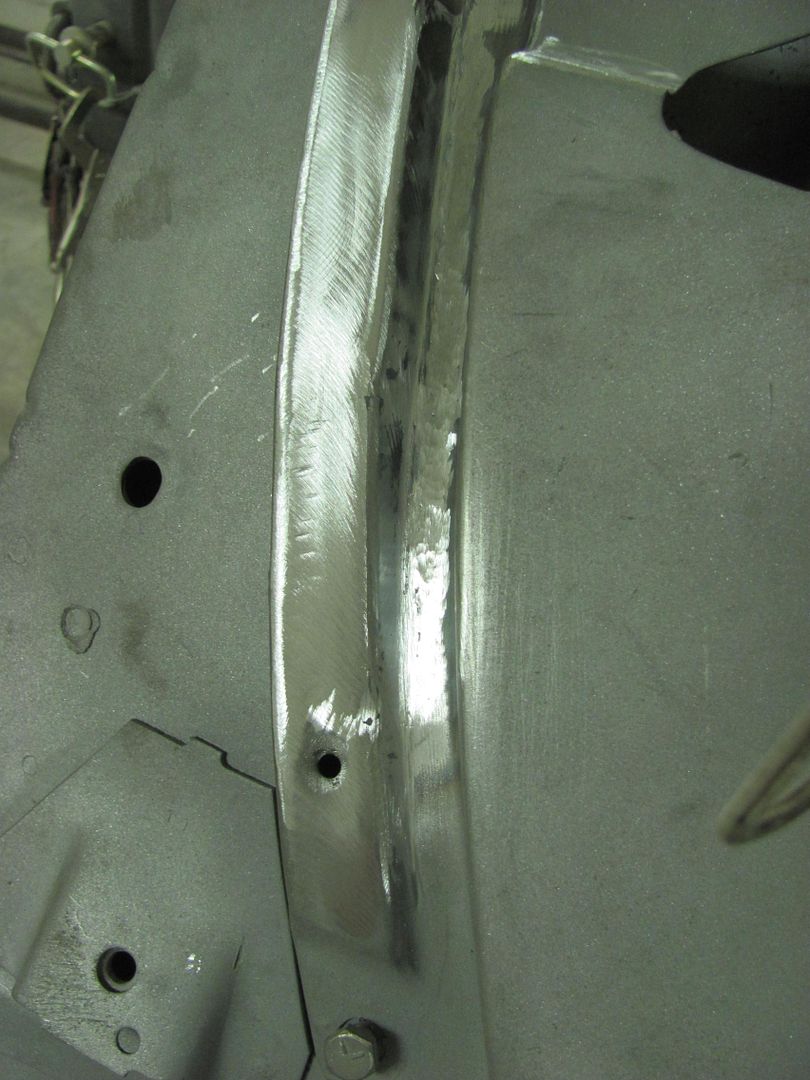
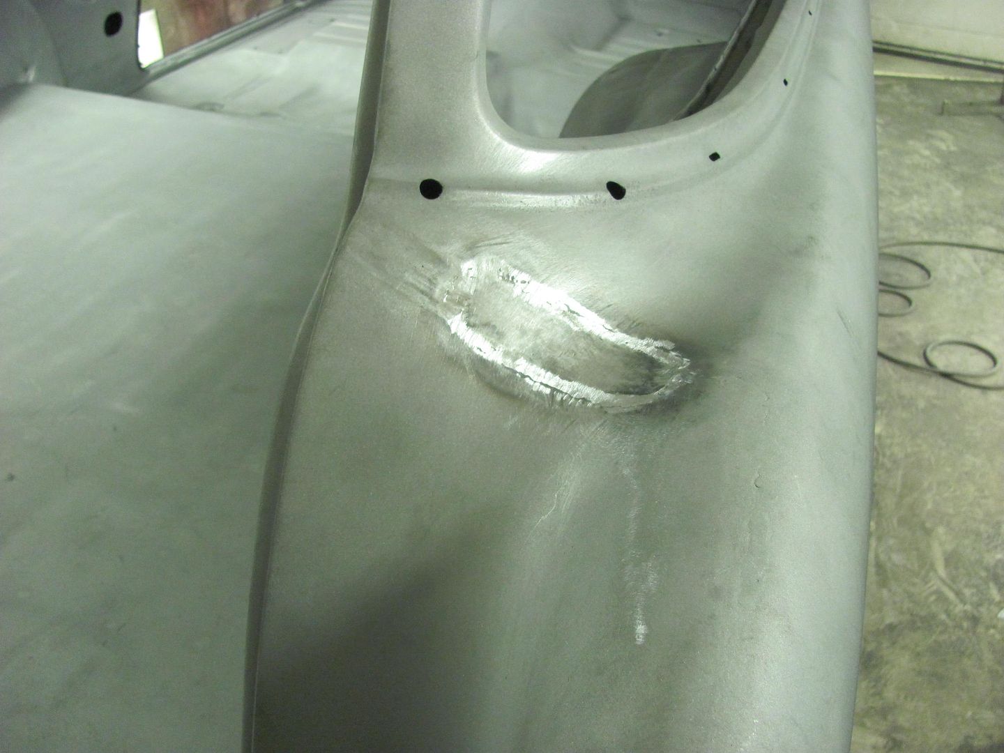
Cowl repair all complete...
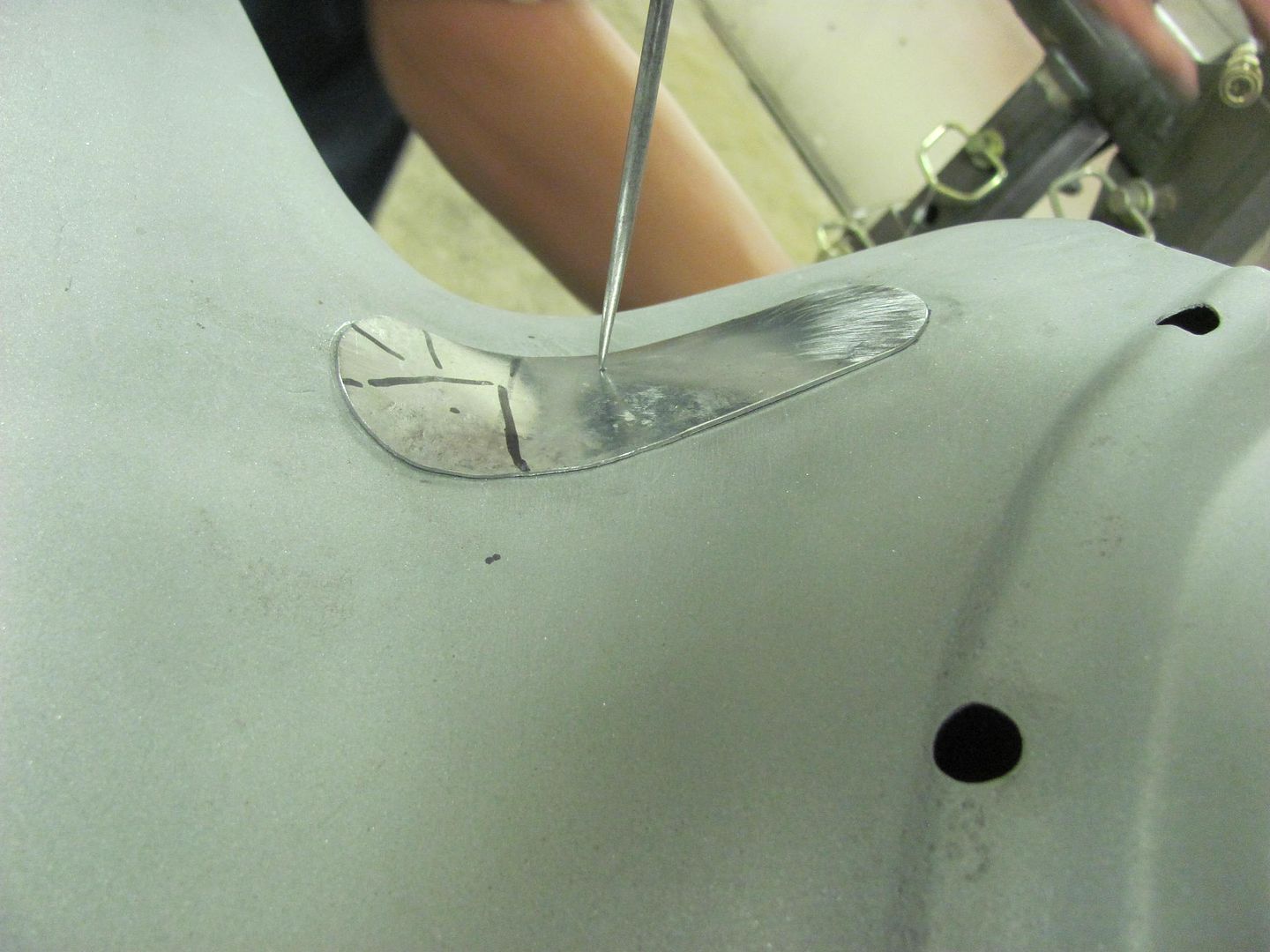
One more thin spot from the media blasting where we had removed the leaded seam...
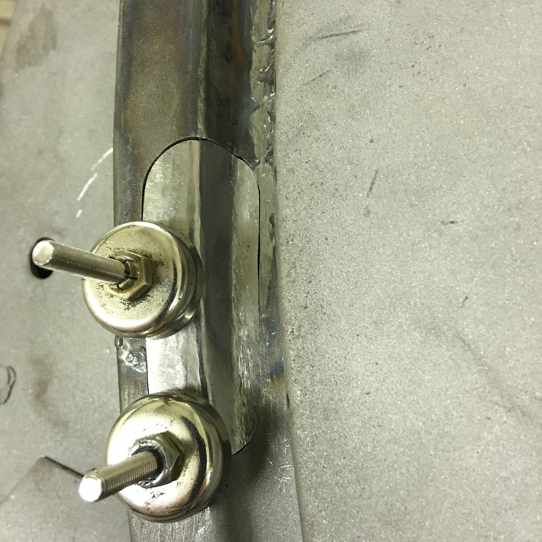
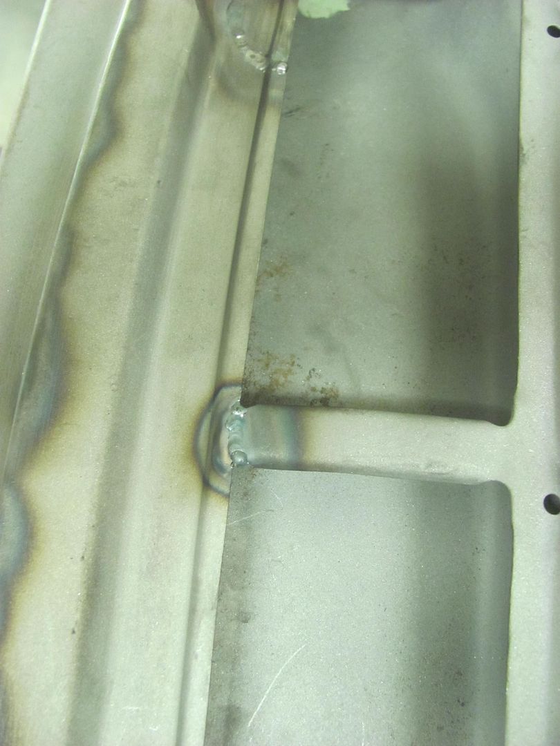
Test fitting the patch for proper contour..
TIG welded in place...
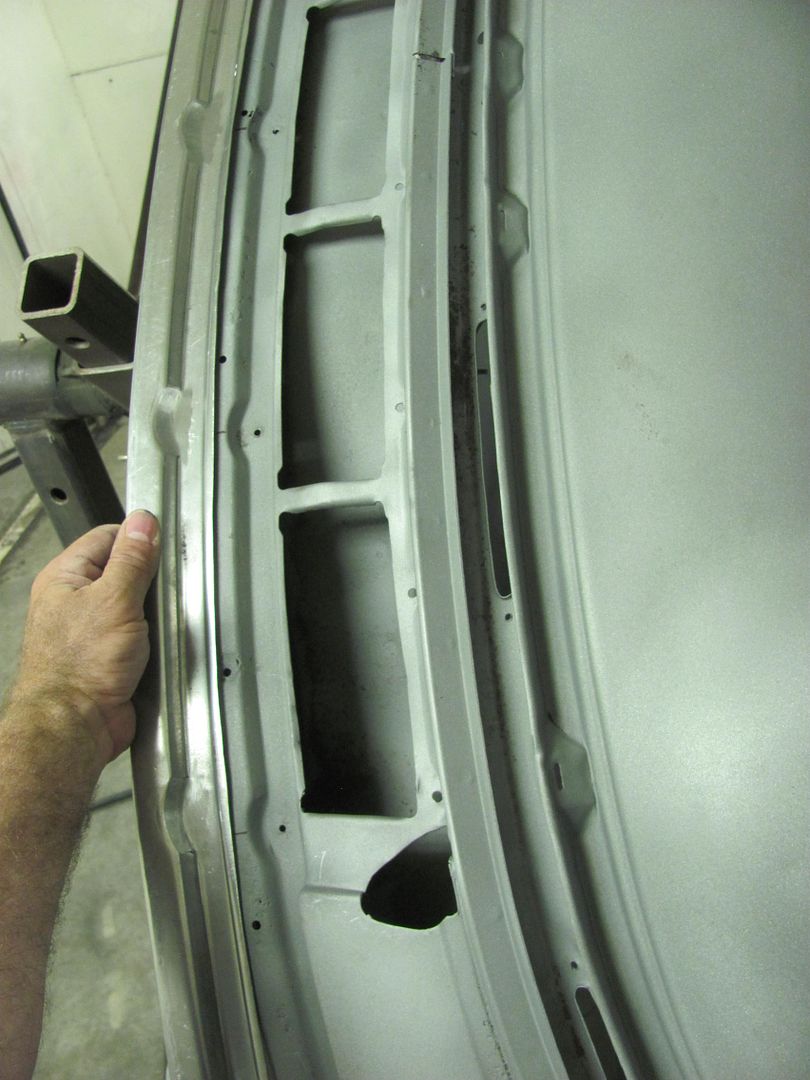
Started off with some SPI epoxy on the underside...
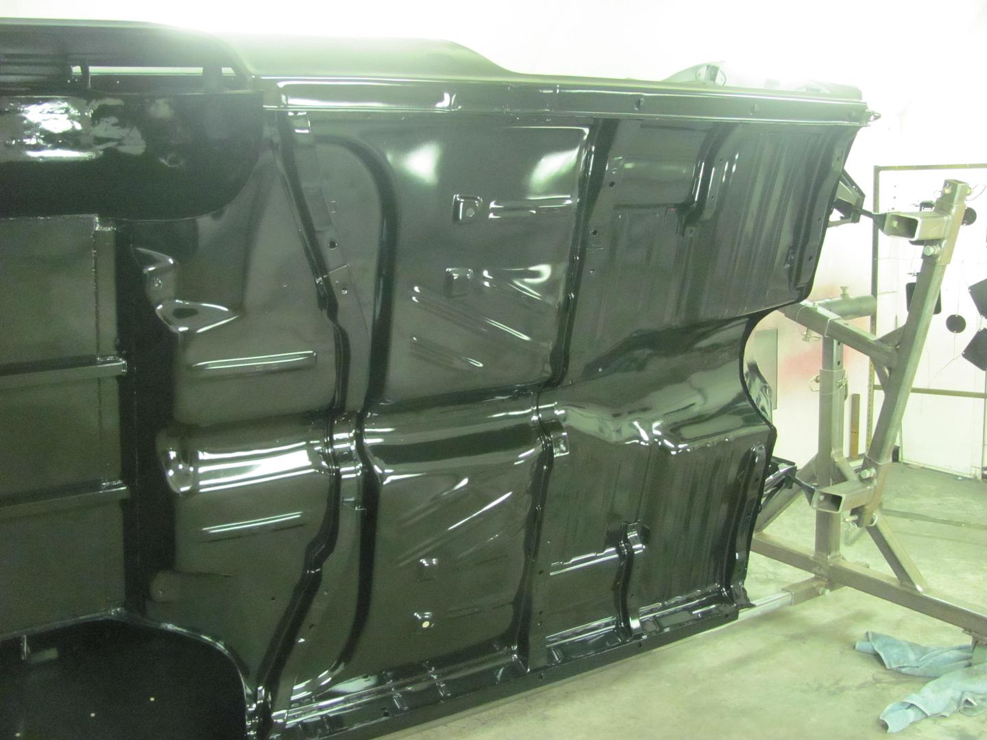
....and then the firewall
.....as well as the new glove box door skin...
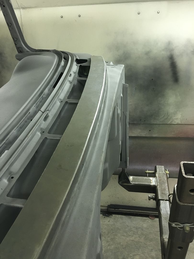
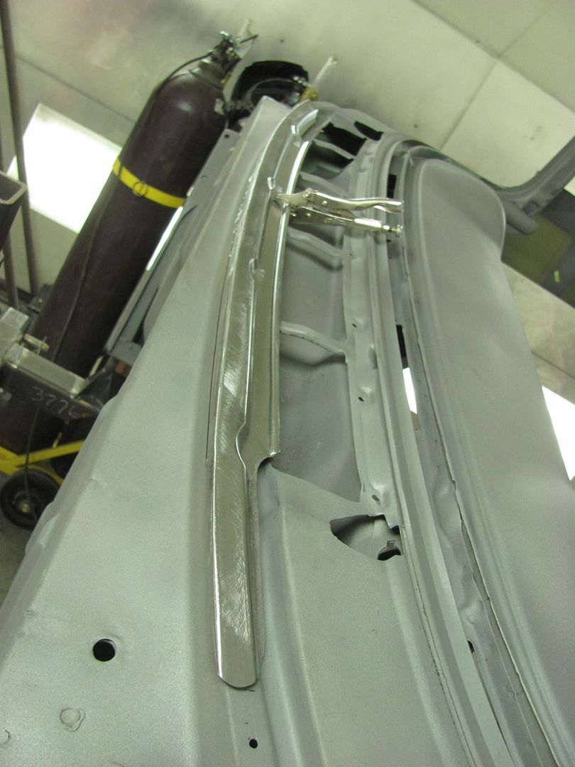
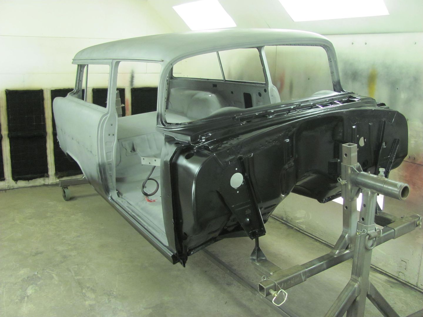
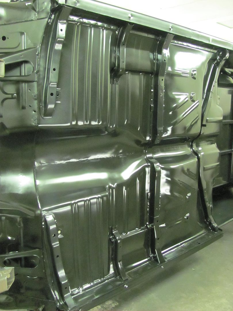
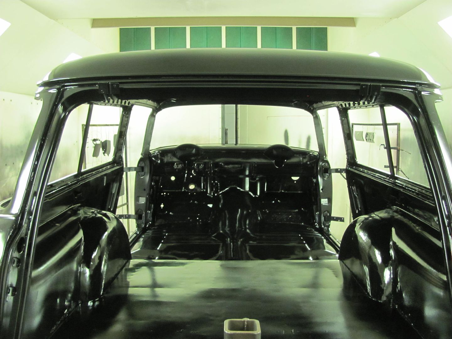
The entire interior was primed by standing through the window openings...
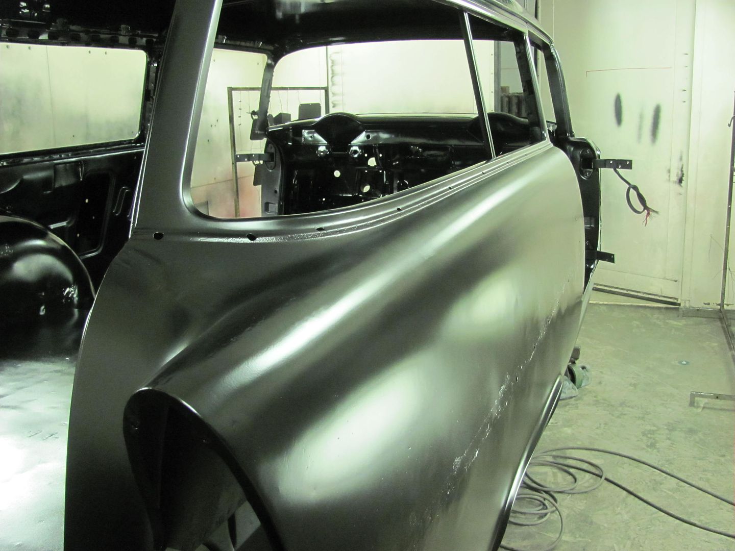
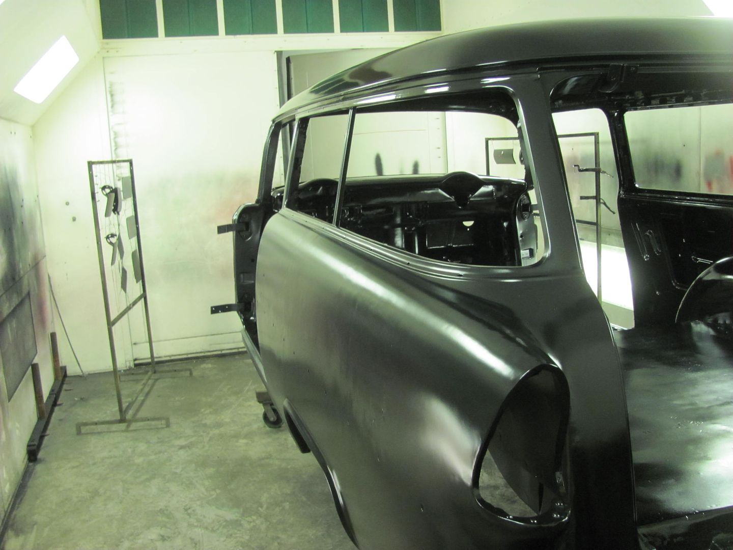
Then the outside was tackled...
Cowl repair all complete...
One more thin spot from the media blasting where we had removed the leaded seam...
Test fitting the patch for proper contour..
TIG welded in place...
Started off with some SPI epoxy on the underside...
....and then the firewall
.....as well as the new glove box door skin...
The entire interior was primed by standing through the window openings...
Then the outside was tackled...
MP&C
Member
Well the epoxy has cured for about three days, time to put the glove box back together... The adjacent areas are scuffed for some official door skin adhesive..
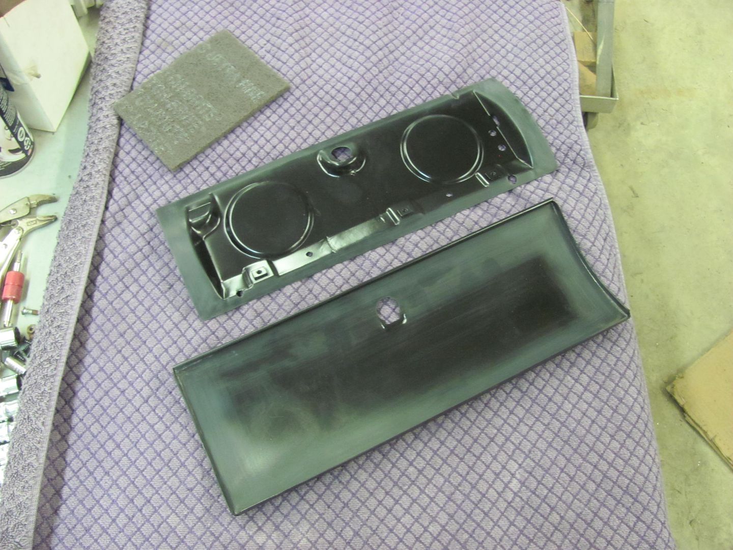
....in the form of some leftover primer from this weekend..
Good thing this gets covered up...
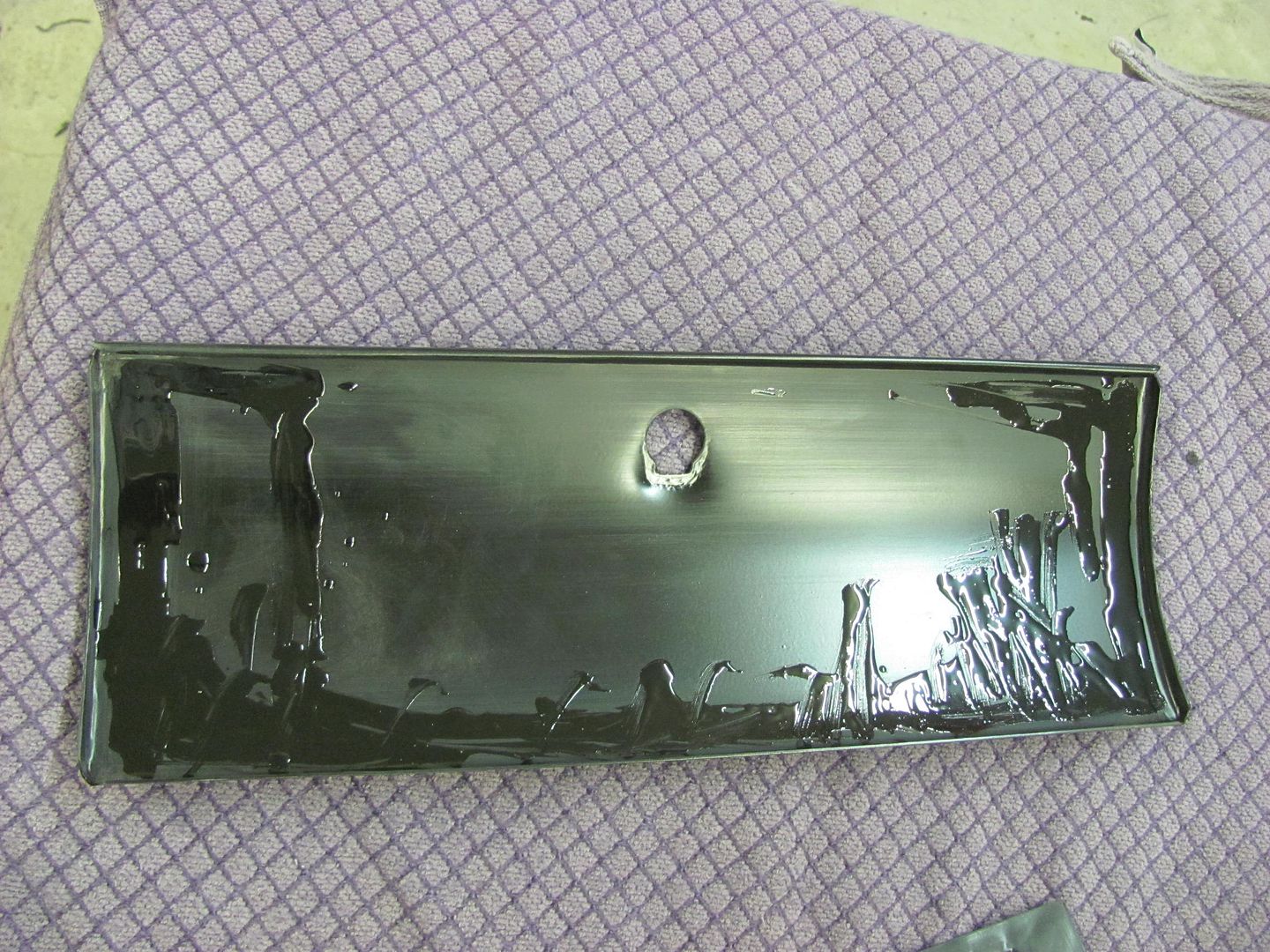
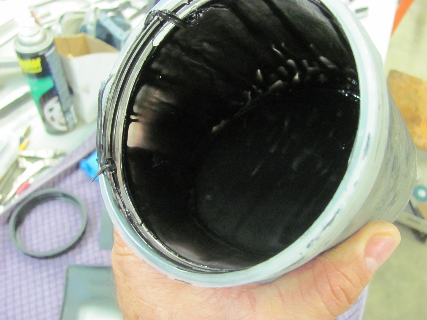
Using the door skin hammer on the leather shot bag, the ends are folded first...
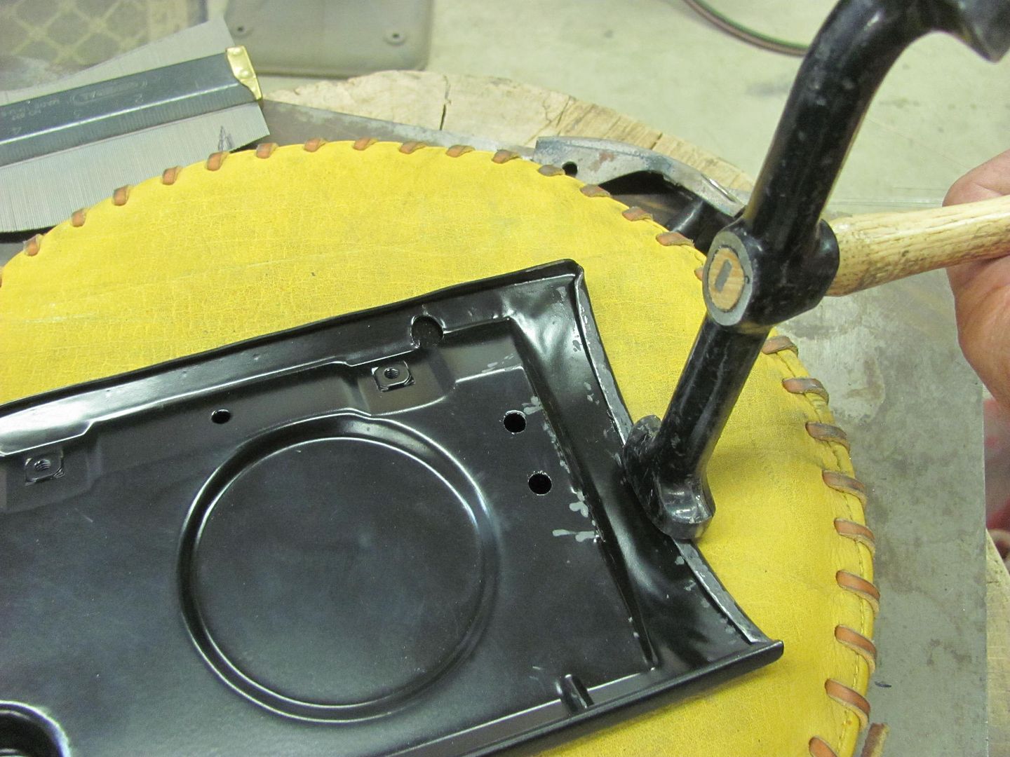
and then the bottom flange...
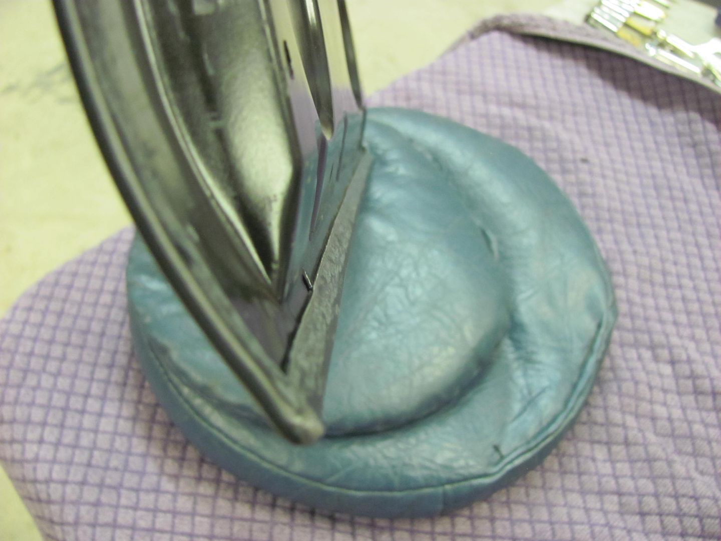
All together...