A donut dolly test sample:
One of the guys over on the metal shaping web sites, Daniel Gunderson, sells the "official" donut dolly. Compared to the typical off-dolly bumping, it works more proficiently in off-dolly shrinking a crowned panel because it supports the bottom side in more than one spot (around the perimeter) as the panel is bumped from the top in the center of the donut dolly. This would seem to be useful in body repair, especially to address high spots found after blocking primer where heat would not be as feasible.
Some time ago, someone on another forum asked for advice in removing an outward roof dent, a result of some over-eager on-dolly stretching in removing dents... I suggested a low-buck alternative to the donut dolly, simply using a PVC pipe fitting. Where it may not work as aggressively as the donut dolly which has more mass, sometimes slower is better, especially when trying something new. Trying this process for myself in the shop, and rather than use the roof of something sitting here, we will use a piece of 18 ga CRS to simulate a roof.
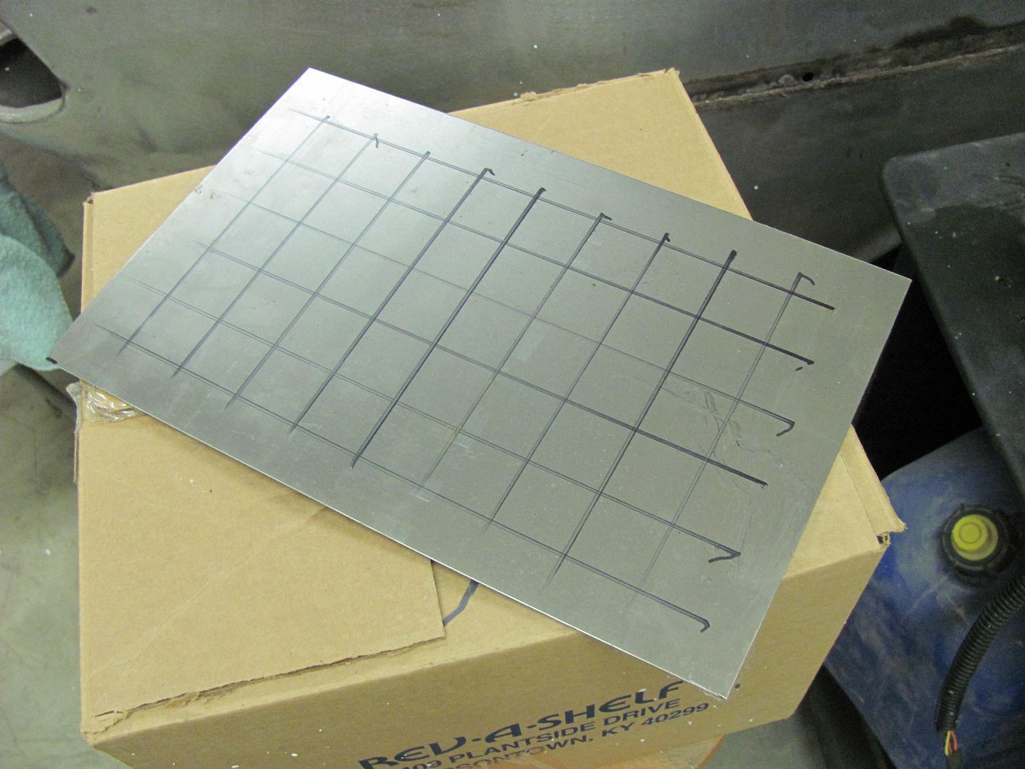
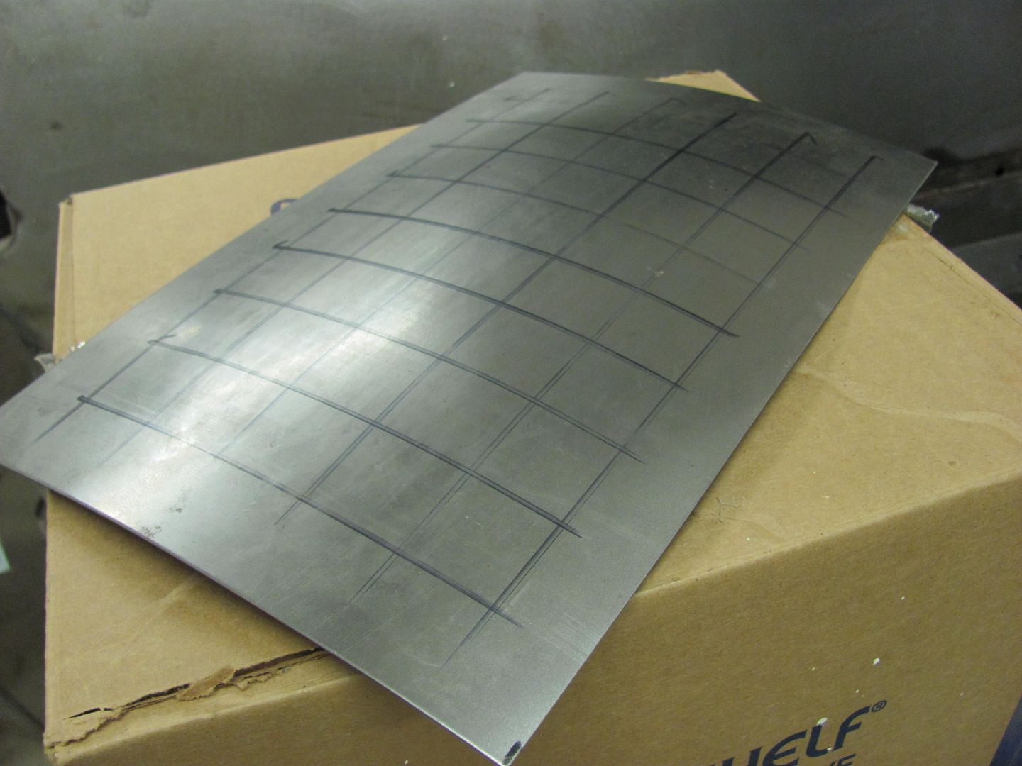
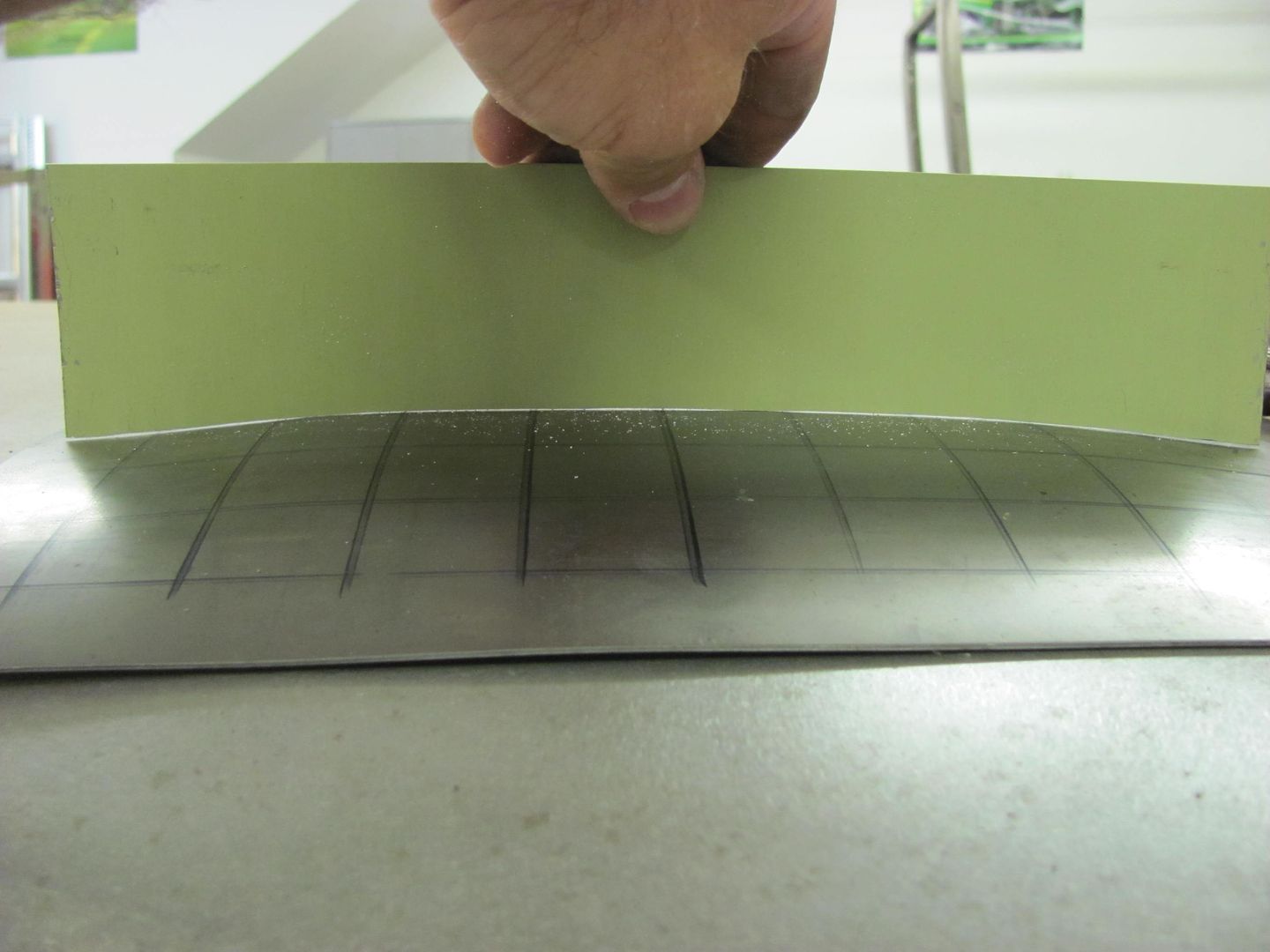
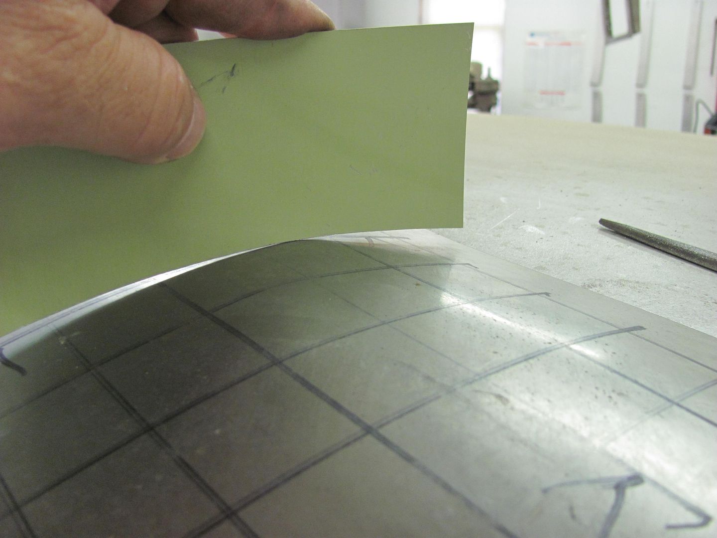
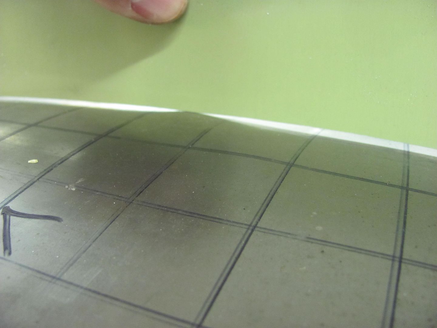
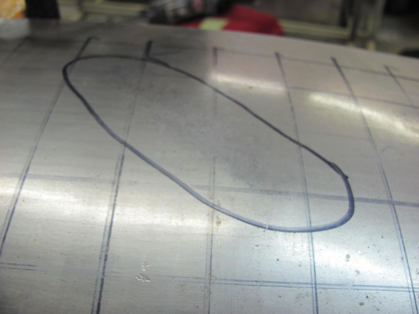
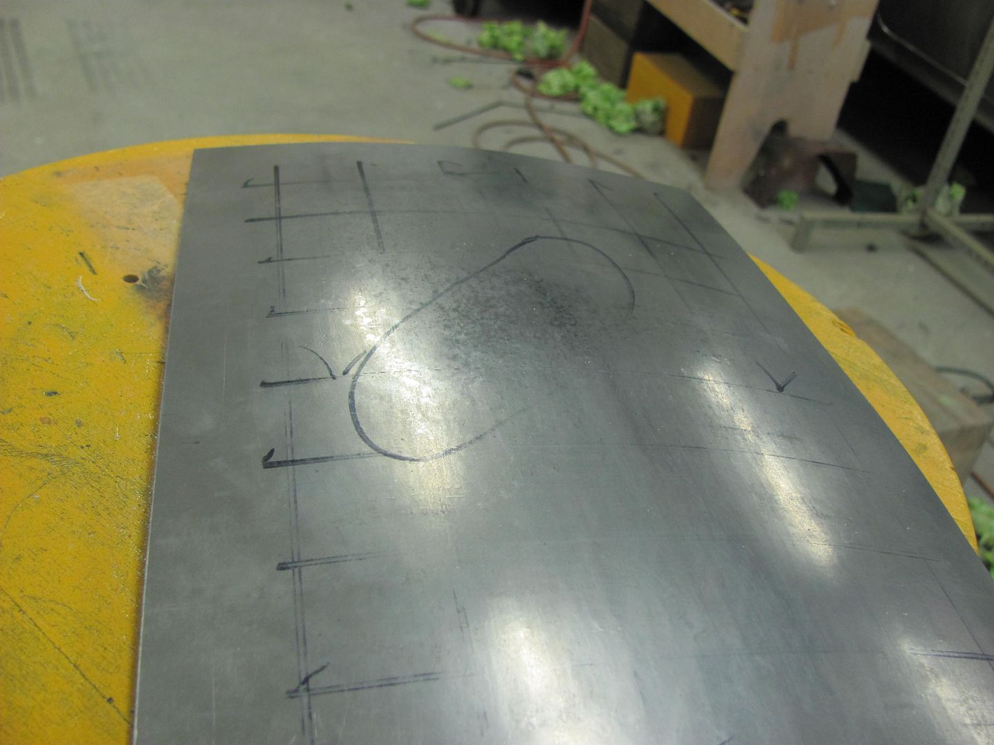
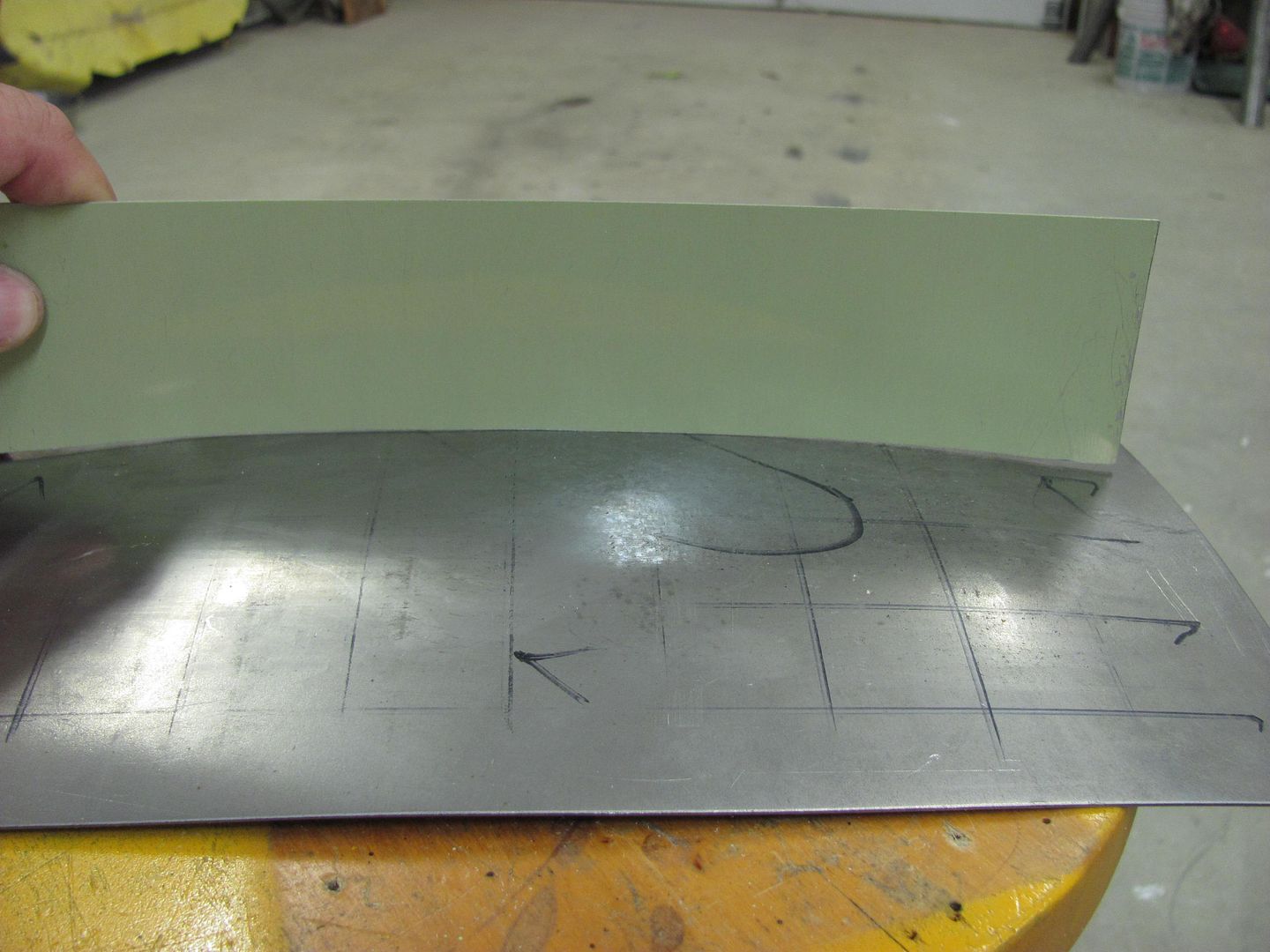
Grid layout for the Wheeling Machine, and completed "sample" roof...
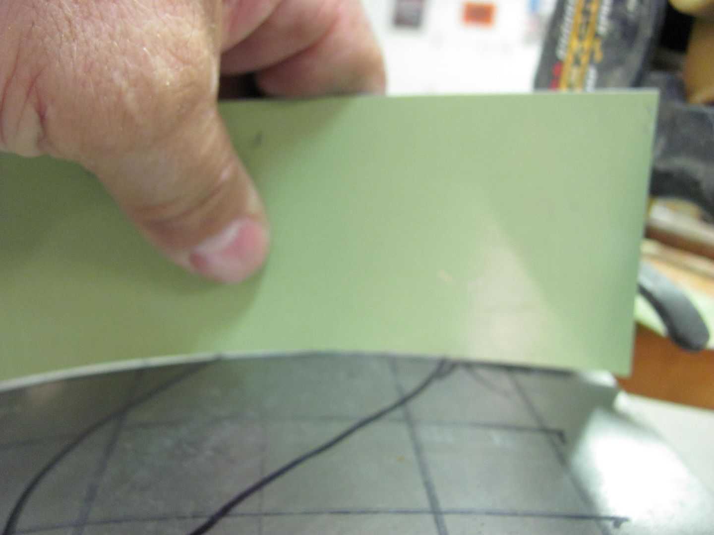
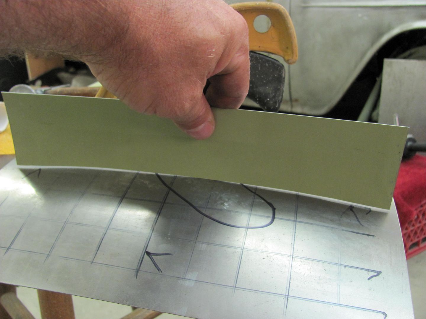
The first order of business should be to make some profile templates. In the case of an actual dented roof, use the opposite, undamaged side. This will allow you to check your progress as you go, and easily find the remaining high spots.
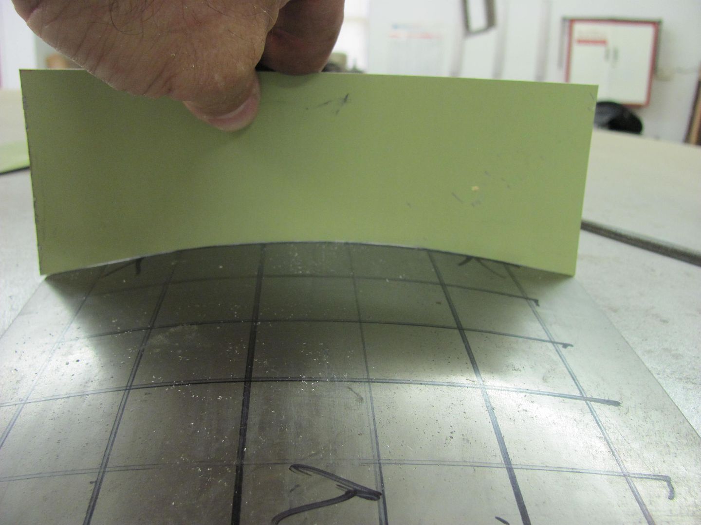
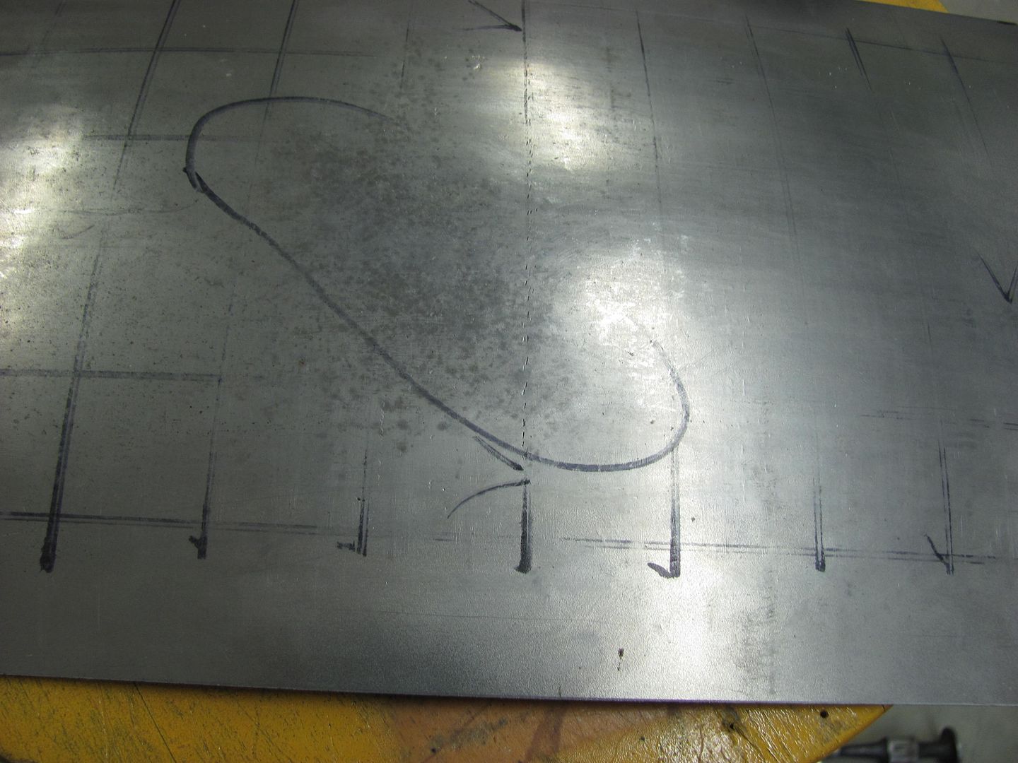
Using a crowned body hammer, a "dent" will be added from the back side, crossing both directions where the templates were taken.
With the dent added:
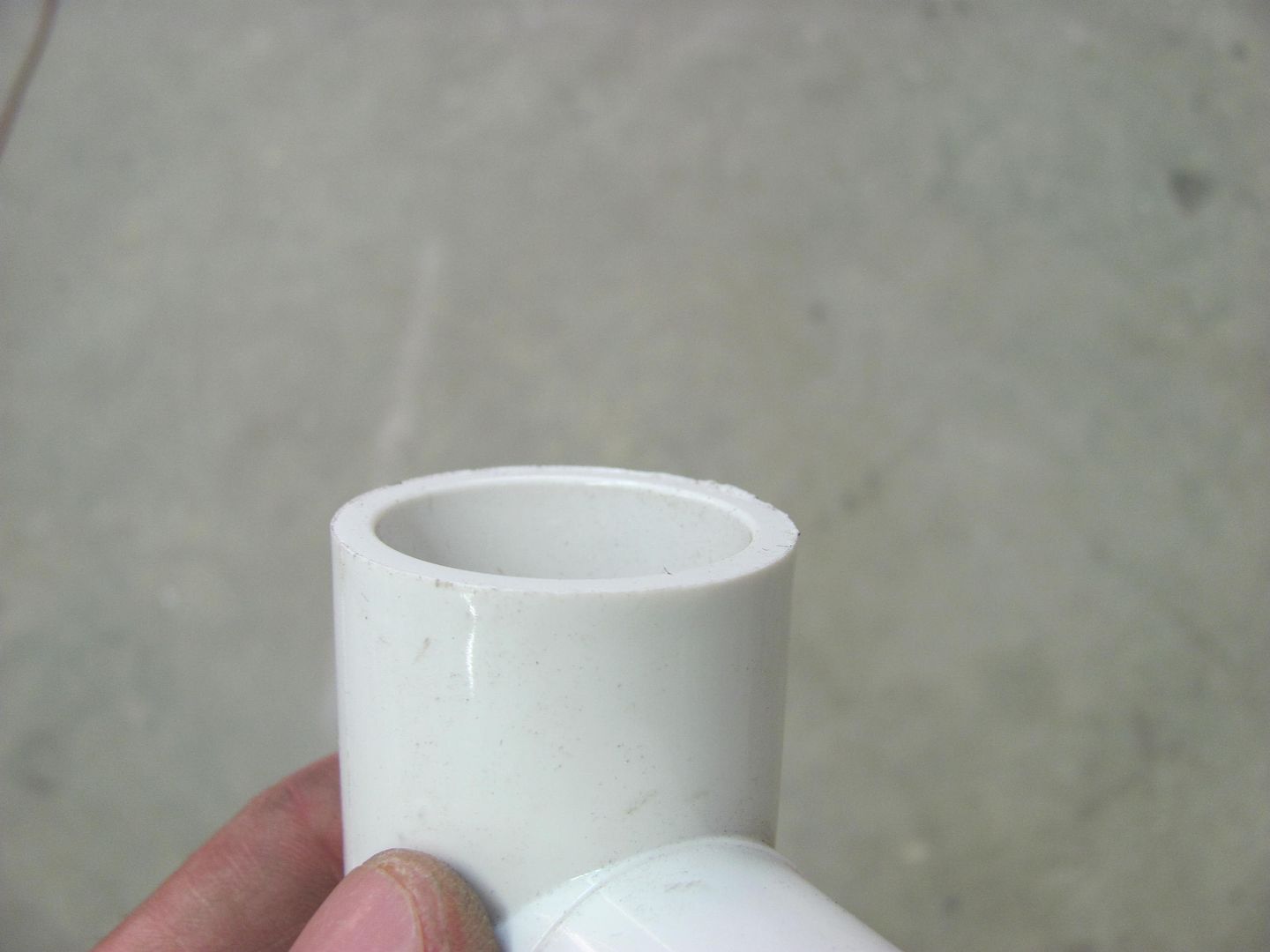
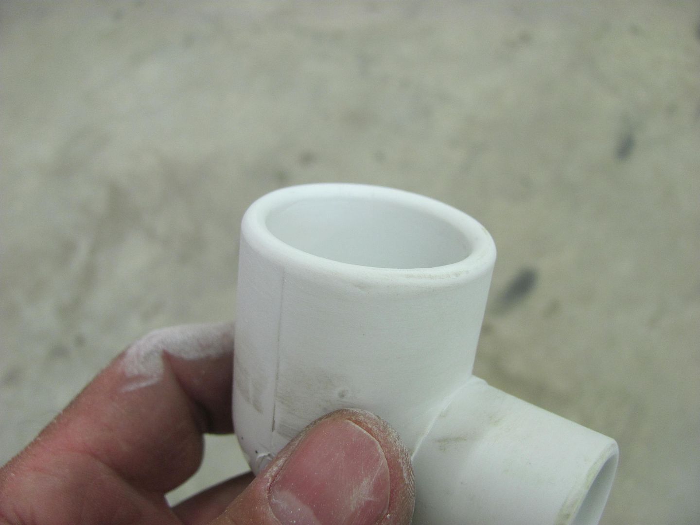
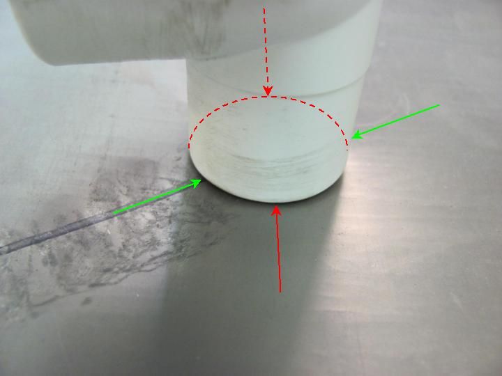
I chose to use a PVC elbow, a "tool" readily available and economical. As with any body tool, they should be free of any burrs that may mar the metal surface, so I sanded a slight radius into the edges...
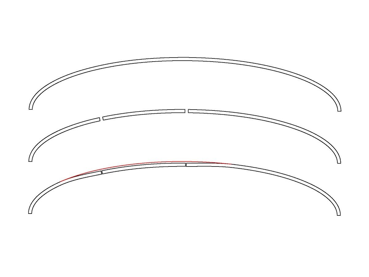
Holding the dolly against the bottom of the panel, you can see that due to the dents it only touches the panel at the red arrows. Based on off-dolly principle, the shrink would occur more prominently in the direction of the red arrows, which is exactly where the stretch lies.
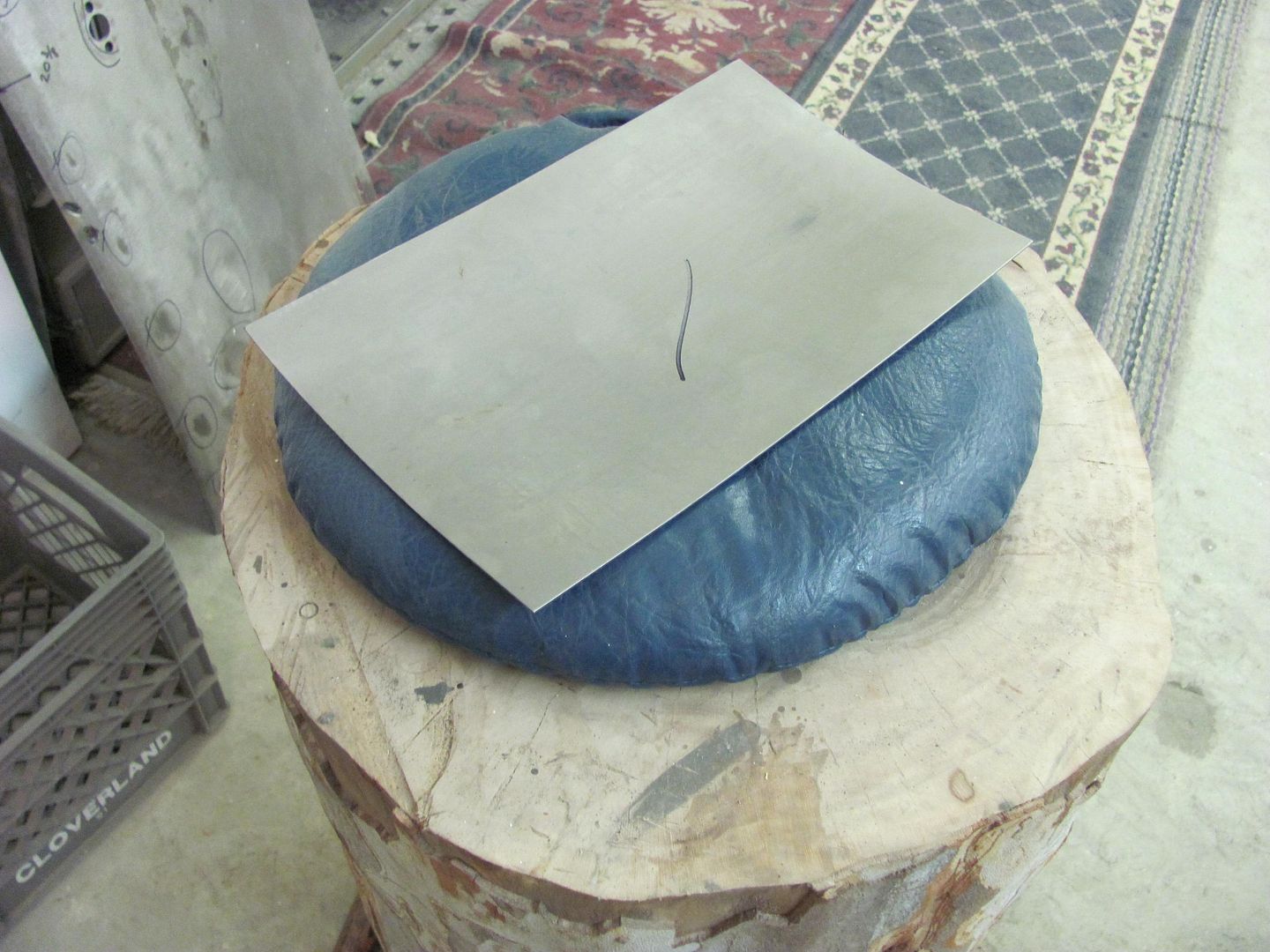
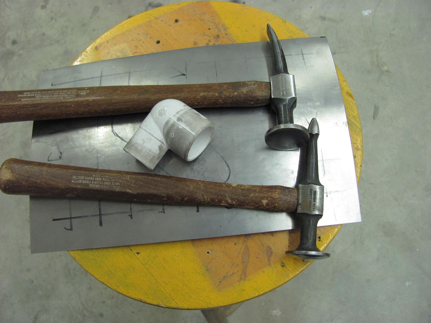
Here are the tools we will use today:
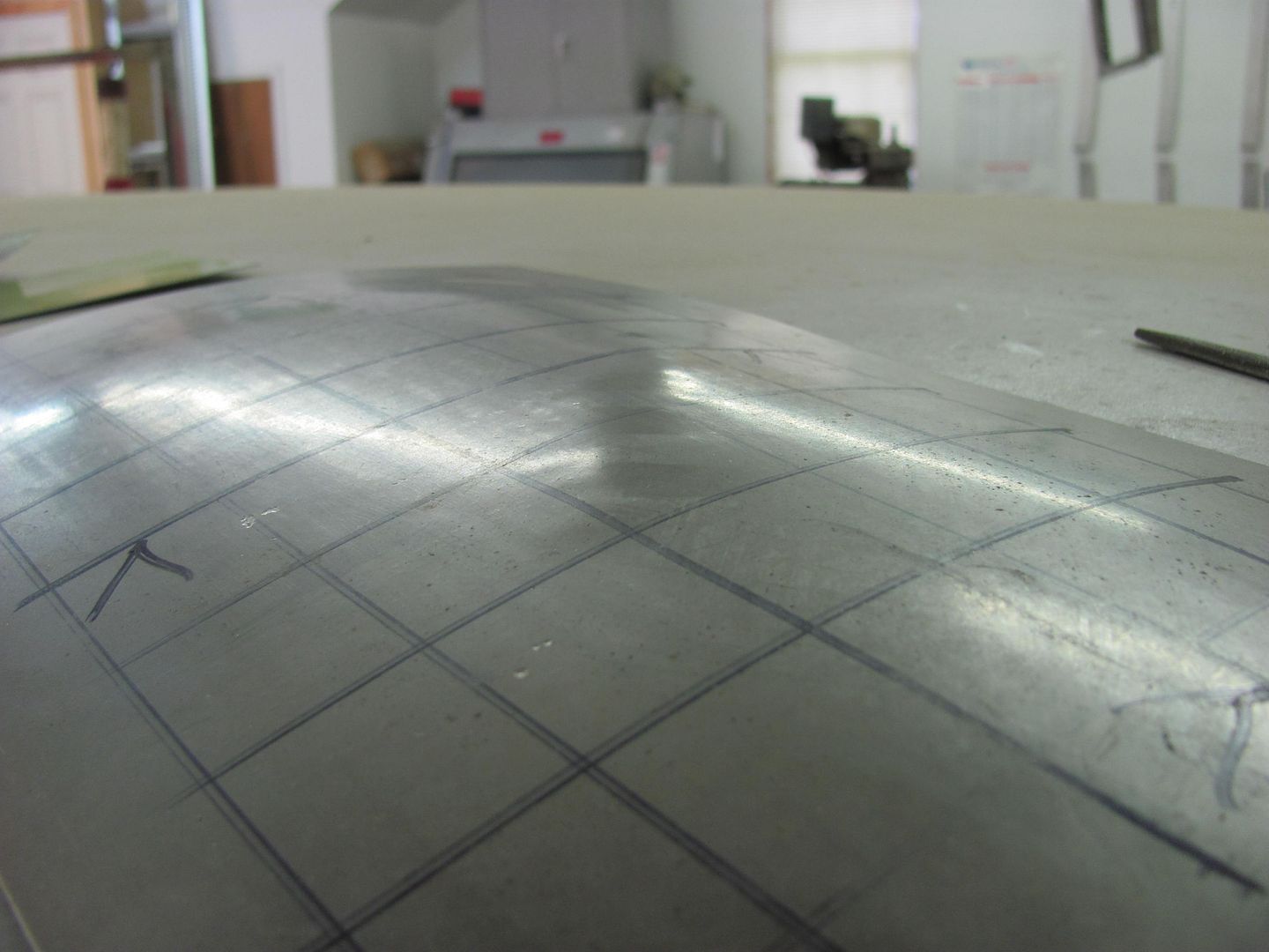
After some off-dolly bumping:
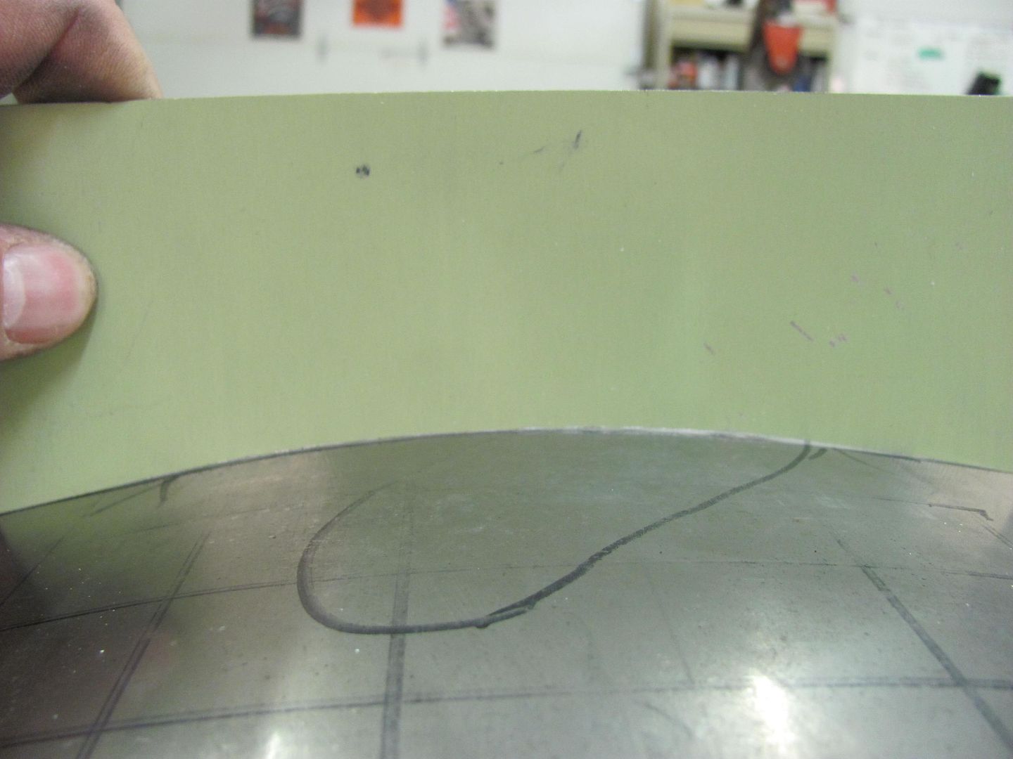
Check with the templates
Progress....these are light taps only with the hammer. We just want to bring down the high spots, not create craters.
Here's where I finished up...
I have a little over an hour in making the panel, denting, and removing the dent. Where I still could have gone a bit more, it was about to a point where high build primer should have masked any remaining imperfections. This dent removal could also have been accomplished with heat shrinking using an O/A torch, etc, but for those times where you may not wish to use heat (primer is already sprayed) and want another option, this seems to work well.