Need help on welding sheet-metal...

AllGoNoShow

Promoted Users
Well, I've been a lurker here for a while and time has come to finally restore my Camaro that I've owned since I was 15 years old. I have been trying to get a little more comfortable with welding sheet-metal over the course of the last couple weeks and have been doing a fair amount of practicing on sheet-metal patches. The machine is a Lincoln 175HD MIG that I've owned for probably 15 years, using Lincoln's .025 wire.

I've been practicing on sheet metal I picked up in the scrap pile at the metal supply outlet that I thought was 20 gauge, but upon closer inspection it seems like it is closer to 22 gauge. I have a sheet of 18 gauge cold-rolled steel but I want to perfect my technique on the thin stuff as I figure than the 18 gauge stuff will be easier. I'm having recurring issues with the panel warping (seemingly no matter how slow I go), and what feels like an excess amount of dressing the spots afterwards to get it to blend in. I utilized a technique I read about here in using a cut off wheel to knock off the high spots of the spot welds, and it did seem to help, but I feel like I am thinning the metal when I switch over to an angle grinder with a 36 grit sanding disc or a 40 grit flap wheel (which I have had more luck with) to really blend it all together and have the edges of the welds disappear.

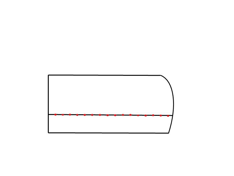
I did the practice panel with pictures below (you can see how much it warped once it was fully welded), but the real problem I noticed is that there are noticeable depressions where the two panels had met after everything is blended together. I was curious so I actually cut the panel in half when I was done and, after measuring, the metal was definitely thinned to 24 gauge in the immediate area around where the welding was done (last picture is the one of the "finished" piece cut in half). You can actually more clearly see the depressions on the piece that is cut it half-as if something in the welding is causing the sheet metal to concave there (which is then amplified on the finished side as I have to grind more away to get it to feel flush). Pictures below (3rd picture is backside of patch)Any tips you guys can share with me?!

Nick
IMG_3333.JPG
IMG_3334.JPG
IMG_3335.JPG
IMG_3336.JPG
IMG_3338.JPG
 
The process of welding did not cause the metal to thin from 18 ga to 24 gauge, the sanding process to remove the welds did that. The wave you see in the metal is a result of the weld shrinking as it cools. It needs to be planished (hammer and dolly) to stretch back out in order to keep the panel flat. Kudos for practicing first on scraps, and not on the Camaro.
 
MP&C- Been going over a lot of your old posts to figure out your process (thanks!). I've got a set of hammer and dollys, but for a newbie like me, can you explain what you mean by planishing? Like where exactly am I placing the dolly and where, how hard, am I hitting it the face with the hammer? Seems like whenever I try to search about panishing in these circumstances, I get a bunch of videos/documents from people talking about and showing the expensive pnuematic planish hammers.

As far as the actual welding is concerned, does the heat/penetration look acceptable on the above piece?
 
As it relates to metalshaping, planishing is a smoothing action. If you were to rough out a shape in a panel using a blocking hammer into a shot bag, it would add shape but the resulting finish would look about like a bag of walnuts. Planishing would be the process to smooth out those "walnuts" to a consistent finish. It would be accomplished using a planishing hammer, then English wheel, etc.

As it relates to welding in a patch.... As you weld, the heat will cause some expansion of the metal as it gets hot. This takes place at the weld and heat affected zone (HAZ-the metal surrounding the weld that has changed color) When it cools off, the molecular structure of the steel realigns such that it shrinks back down more so than what it was previously. Side note- whether you are welding sheet metal or 1" thick plate, any welding process will result in shrinking of the weld and HAZ.

Planishing in this case would be the process to add a bit of stretch to the area that has shrunk in order to restore the original shape of the panel. It is typically done on the weld itself and to a lesser extent to the HAZ area, using a hammer and dolly. When you strike a hammer face into a dolly you will hear a PING. When you are planishing, it is hammer on one side, dolly on the other, and you want to hear that PING. You hear the ping, you are stretching. So when using the hammer and dolly to planish welds, it is advantageous to have a weld proud on both front and back side of the sheet metal, as these give you a "target" that is off the surface of the sheet metal for a more effective stretch of that one weld dot by its lonesome self. Dolly on one side, hammer on the other to strike the weld dot.

Looking at your weld "dots", they have a pin hole in both sides on many of them. This is an outgassing that occurs as the puddle cools. I think you can remove some of that by using a hotter weld. Turn your heat up, add more wire feed speed if it tends to blow out, and shorten the trigger pull elapsed time.. So in essence, despite the heat being hotter from the machine's perspective, because the trigger is not pulled as long, the heat the panel sees is the same or less. (if we get the operator adjusted as well ;) ) I think you'll see a hotter, shorter time-weld has the puddle sitting there boiling less, so the pin holes SHOULD be less an issue.
 
As far as penetration, you have a good weld proud on the back side, good for planishing. Note the weld seam is still visible. If we overlap the weld dots, it will resolve that so when you weld, planish, grind, and then do sanding after all is final, we should have a seam that duplicates the factory metal. No stepped flanges, no skipped seams, just a solid sheet of metal.

As to the process I use for MIG welding a panel.....

Let's say we are installing a lower door skin to repair some rust. The repair panel has been trimmed for zero gap (or as close as we can), and the panel is tacked on, starting at one end, and working PROGRESSIVELY TOWARD the other. Don't skip around from one end to the other as you have a greater chance of misalignment in that you may have more metal trapped on one side than the other, which will result in a buckle from the excess metal once the welds bring it together. So I start at one end, tack, move an inch or so, align the panels together, make another tack, repeat. This insures the panels are correctly aligned as you work progressively from one end of the weld seam to the other.


doorpatchtacked.jpg


Once done with the last tack, go back to the beginning and use a hammer and dolly to planish each weld dot, working in the same start to finish pattern. Now go back to the beginning and use a 3" cutoff wheel to grind the weld dots down to just above flush, both FRONT AND BACK, as this gets the weld prouds out of the way for both planishing the next sets of weld dots, and also removes all the excess weld that is going to change the heat load. A weld bead can be up to 4-5 times the thickness of the parent metal, grinding it down keeps the effective metal thickness the same throughout. I grind to just above panel height for a weld seam like this, and final cleanup with a 3" roloc sander will be used at the end to dress the seam to the parent metal. Here's a video that shows the grinding process, but as this is a plug weld it is dressed immediately following. Again, a full weld seam gets dressed at the end. Much less chance of taking away too much metal.

https://www.youtube.com/watch?v=V2WHT_zMOE8


Now that those welds are down and out of the way, let's add the next set. Here I'll overlap the last set of welds by about 1/3 to 1/2. Whatever the distance of your overlap, keep it consistent throughout.


doorpatchsecondtack.jpg


This method helps to eliminate any missed areas like what occurred on the back side of your test piece. Again, start from the same spot you did before, overlap the first weld dot where you started, go the the next, overlap, repeat, until you get to the end. Then go back and repeat the planish from start to finish, then grind weld dots from start to finish, both FRONT AND BACK, and then repeat the overlap process again. Keep repeating the process until the weld seam has been finished, then use a roloc sander to dress the little bit of remaining weld to flush with parent metal, both front and back side.


If this sounds like a slow, monotonous process, yes it is, that is the intent. This promotes consistency in the welding process, from fitup through to final welds dressed. At no point is it necessary to cool the welds, by the time planishing and grinding are complete, the welds on the panel are plenty cool to the touch. Any artificial cooling serves no purpose.
 
Last edited:
Planishing amount is dictated by how much is needed to restore the panel crown. It comes in handy to have profile templates made top to bottom, and front to back, through the area of your weld seam (taken/made beforehand).

For flatter panels such as quarters, I think some may be under the misconception that because a panel used to be flat, and now that the metal has moved away from its flatness, well obviously the metal has stretched. THIS IS NOT THE CASE! There are no cases where a welding exercise will result in the permanent stretching of metal. Sure the metal will stretch while exposed to the heat from welding, but as the area cools, the molecular structure re-aligns and becomes tighter, closer than they were previously- resulting in shrinking.

Looking at the cross-section of the quarter, let's examine those shrinking principles. Where this is a low crown panel, and the heat often wreaks more havoc on the center, flatter area of the panel, in many cases it will shrink, lose some of the crown, (become more flat), and possibly start to oil can as the metal loses its shape. In the picture below, the red arc would represent the original shape, and the blue shows what occurs as the weld shrinks the surround area; the arc loses some of its length and pulls the adjoining metal into a valley.

crown.png


To correct this, the hammer and dolly principles are used. If we were to wait until the entire weld is complete to planish, the weld will most certainly pull into a valley. By using the weld/planish/grind/repeat that was discussed in the previous post, we can keep the shrinking and distortion from getting to far away from us, where when done it should be a matter of minor touchups to get the panel squared away. Use caution, no matter what type of panel you are working on, to not get trapped with "tunnel vision" and only focus on the immediate weld area. We should always keep an eye on the surrounding area as well, and check your progress with some long metal strips/rulers laid across the area to help see where the shape needs to move. On a quarter, I like to lay a long ruler across the seam to read the dip, and then also drag it along the panel parallel with the seam, to see any change in the crown from the unshrunk area and into the welded area. Any outlying area that becomes loose may be an indicator that the weld area is still shrunk too much and is drawing down that area. Hopefully this will give you a better understanding to what happens when welding to keep the panel from becoming a potato chip..


Remember, on-dolly, metal pinging sound = stretching.


To explain what is occurring, when using On-dolly, hammer and dolly directly lined up with each other on opposite sides, and when you strike the hammer you will hear a ping as the force travels through to the dolly. (red arrows) The secondary action is that this forces the metal outward in all directions (blue arrows), in essence stretching the metal.


OnDolly.png


.
 
Last edited:
Thanks for taking the time with that...I actually understand the planishing part now! And you are right on the monotonous part....I put in several hours just practicing doing that sheet metal patch. I seem to figure something new out every-time I pick up my welder. Oddly enough, I've built stuff my whole life but working with metal and welding is about as satisfying a thing as I've done (and I'm sure spending hours in the garage away from a wife and three little toddlers has nothing to do with that!).

Going to do some more welding in the next few days and will post my results.
 
Fantastic job explaining this process. I have seen a number of videos showing it done but most lack the detailed explanation of how and why it is done.
I have welded many patches into place with my MIG and now understand the things I was doing wrong. Thank you!
 
I also appreciate the time and effort to put this to "pen and paper" Robert. That will go a long way to help many get to where they want to be with their metal work and welding.

Well done.
John
 
Thanks for your contribution in all this, Robert. Some of this, along with my wheel well arch repair really needs to go into a pinned thread in the metal working section. BTW, I've looked through many of your YouTube videos and, unless I've overlooked it, don't see one on planishing. A good video on that would be great! I'd like to see the hammer and dolly you use for that, hear the sound of the blow, note the force of impact, and how you hammer on that weld. That's just a suggestion out of appreciation that stems from your continued input here in regards to this very topic.

http://www.spiuserforum.com/index.p...-for-wheel-arch-repair.7039/page-3#post-76772

OP, Camaro in NY? I'm thinking you're going to get a lot of welding practice. Good post!
 
Machspeed-Luckily I've owned the camaro the last 22 years and it has been garaged all of the time (it was my first car when I was 15). Needs the lower quarter patches, a patch or maybe a whole new tail-panel and some front floor panels (the thin sheet-metal I bent with a hammer and flux-cored over the holes when I was 17 just isn't going to cut it!). Luckily I bought a rust-free super straight 78 Camaro when I was about 19 that I still have in parts that will be providing all of the removable parts. The plan is for some flat-back SPI paint (or maybe just leave it in epoxy?).

MP&C- So in what order do you suggest doing the spot welds when doing a patch panel like I did where the patch is surrounded entirely by the original metal? Clockwise direction? Or should I be alternating between both parallel lines on the top and bottom and then both the horizontal lines? And how does this process get effected by situations where access to the back of the panel is limited? For instance, when I get to doing my lower quarter panel patches on my camaro, I will be able to get a dolly in there through the door jamb vent hole, but there is no way I'll be able to grind the proud weld dot down on the rear of that panel.

Going to go out in the garage now and throw some sparks!

Nick
 
Nick, for an "interior" patch that is completely surrounded like you did in your practice, I would first eliminate the sharp corners and add a radius, or if possible, use a round or oval. This helps to eliminate the shrink stacking that happens in inside corners.. Next, if it were to go across a body line/crease, you would want to tack there on either side to lock in that detail and then tack elsewhere. If the interior patch were just in an otherwise flat area with no other details, any tacking along one side would tend to pull to that side. in the interest of keeping things centered, I would tack the middle left, insure the patch is still centered, tack the middle right, and then skip from there, aligning the panels as you go. Ideally the panel would be a nice snug fit to limit panel movement/pulling adjacent areas low. But as we are all human and there is likely to be a slight gap, then center to keep things consistent.

For tight areas and planishing/grinding, this is why you look first and foremost for rear panel access in determining where to put your weld seams. (should have included that in the earlier posts, I'll have to go back and add it) I understand that is not always possible. In that case you should employ the services of a teenage "apprentice" that is more a contortionist than us older folk. ;)
 
So I did some more practicing today. I most certainly need to purchase a better hammer/dolly set (I think mine is a harbor freight cheapo kit) and do a little more research on utilizing those tools. I did a much better job limiting the overall warpage using your method, but I still have a problem where the area of the seam where the two pieces meet and where I am welding tends to end up in a small depression (see attached picture). And with this depression, it is increasingly difficult to do a final sanding with an angle grinder without thinning the surrounding metal. If I were to flip the piece over, the backside of the seam where the two metals meet forms a slight ridge. I don't know if the cheapo hammer/dolly set is just not good enough at stretching the metal in to flatten this area? How many times do you traditionally hit the spot welds to help stretch the metal utilizing your process?
IMG_3344.JPG
 
but I feel like I am thinning the metal when I switch over to an angle grinder with a 36 grit sanding disc or a 40 grit flap wheel (which I have had more luck with) to really blend it all together and have the edges of the welds disappear.


Sorry, I missed this earlier. The main reason we use a cut-off wheel is that while holding it perpendicular to the weld we have an unobstructed view so we can grind the weld proud and ONLY the weld proud. If you touch to one side or the other, you can see it and quickly correct and get back on the weld. Watch this again, and see how the cut off wheel is moved, side to side, etc and stop short of the parent metal, because you can see it!


Clean up afterward should be about a 60 or 80 grit. No need for 24 or 36 if you have used the cutoff wheel properly to get the weld just about flush.

Next, the main reason NOT to use a flap wheel, is you can't see what you are doing and it quickly takes your metal thickness down to 24 gauge. Try a 3" roloc with a quality 60 or 80 grit WITHOUT pushing on it. Let the abrasive do the work, if you overheat it from pushing, you overheat the metal and also the sanding disc, and then the abrasive wears out prematurely. Look at this thread, where I purchased 6 of these boxes in Sept 2018. Still have 2-1/2 boxes left... Not a fan of the cheap stuff, you pay more in the end.


For planishing, did you hammer/dolly while the dots were by themselves or multiple together? Here, I would say planishing for each single weld dot is finished when the panel is flat again. However, a flat sheet about the size you are using in some ways makes a bad "test" piece as it has no crown or an extra 15-20 square feet of sheet metal that tends to hold the shape of the rest of the panel. A panel on the car also tends to hold the panel stationary as do your planishing. So on a car's quarter panel, if we need the weld to come outward as it pulled into a valley, we can apply some pressure from behind on the dolly to persuade it the direction needed. You cannot apply this pressure to a loose panel. So for your "flat" test panel, realize you won't be able to duplicate the feel of this planishing with it being loose and without a crown. Just cheat, and flip it over, hammering from the back side to bring out the "low". At least you can see how much planishing is required to get rid of the wave.
 
Some great information here! The difficulty I find is when you can't get to the backside of the panel to accomplish the planishing process. Braces, obstructions and accessibility often can make this difficult or impossible in some cases.
 
While obstacles do exist and it is near impossible to eliminate all of them, weld placement or panel choice can help out. A quarter panel repair panel through the middle (which is normally the flattest area) is more likely to show distortion over a quarter panel that comes up higher where there is more crown to help limit distortion but also more access for planishing. A patch on a rocker panel is almost a guarantee to pull into a valley at vertical welds but installing a full piece rocker using spot welds or plug welds will have minimal distortion.
 
However, a flat sheet about the size you are using in some ways makes a bad "test" piece as it has no crown or an extra 15-20 square feet of sheet metal that tends to hold the shape of the rest of the panel. A panel on the car also tends to hold the panel stationary as do your planishing. So on a car's quarter panel, if we need the weld to come outward as it pulled into a valley, we can apply some pressure from behind on the dolly to persuade it the direction needed. You cannot apply this pressure to a loose panel. So for your "flat" test panel, realize you won't be able to duplicate the feel of this planishing with it being loose and without a crown. Just cheat, and flip it over, hammering from the back side to bring out the "low". At least you can see how much planishing is required to get rid of the wave.

I think I am slowly learning that this is the case. The small test pieces want to "oil-can" as I think it is referred too (kind of like the metal has some back and forth "spring" in it) even after the initial few spot weld tacks. I did tacks on the 2 long sides of the piece below, and even though everything was initially lined up perfectly and fit very snug, the side closest to the bottom of the picture, as you can see, started oil-canning on the outside of the patch and wouldn't line up. No amount of planishing on the other weld dots seemed to straighten anything back out....I actually had to planish the area outside of the patch where it was oil-canning to get it to line back up.
IMG_3341.JPG


I just ordered some of those sanding discs you mentioned (I just got the 2" ones tho) and am considering trying to use a different wire instead of Lincoln's (it just seems super hard to grind away-even when I hit it with a good sanding wheel on a 4 1/2 angle grinder). Any recommendations? I've heard of an "easy-grind" .023 wire that seems to get mixed reviews. Just going to bite the bullet and get one of Martin's entry level body hammer/dolly kits if I can't find anything used on ebay.

The good news is that I am getting remarkably comfortable with the welding part of all this. Do you utilize this same process when doing things like floor-pan patches, where distortion is less of a concern because it won't be seen? I will probably tackle that first on my own project.

I also noticed from some of your other threads, you epoxy the back of the patch panels you make before installation. Do you leave the paint off the edges of the patch panels or do you just paint it all and the welding heat burns it off where it needs to? If the part is an aftermarket patch with that black coating already on it, do you still epoxy it or just leave that coating as is?

Sorry for the million questions, you have been remarkably helpful!

Nick
 
Back
Top