Wagon Progress

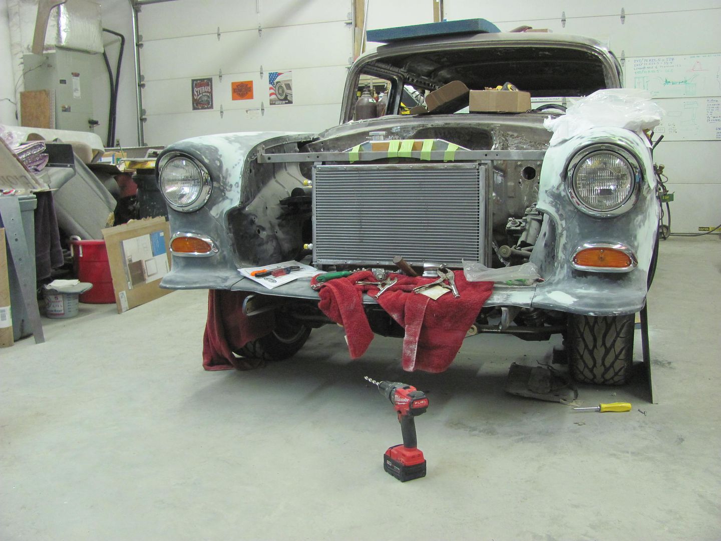
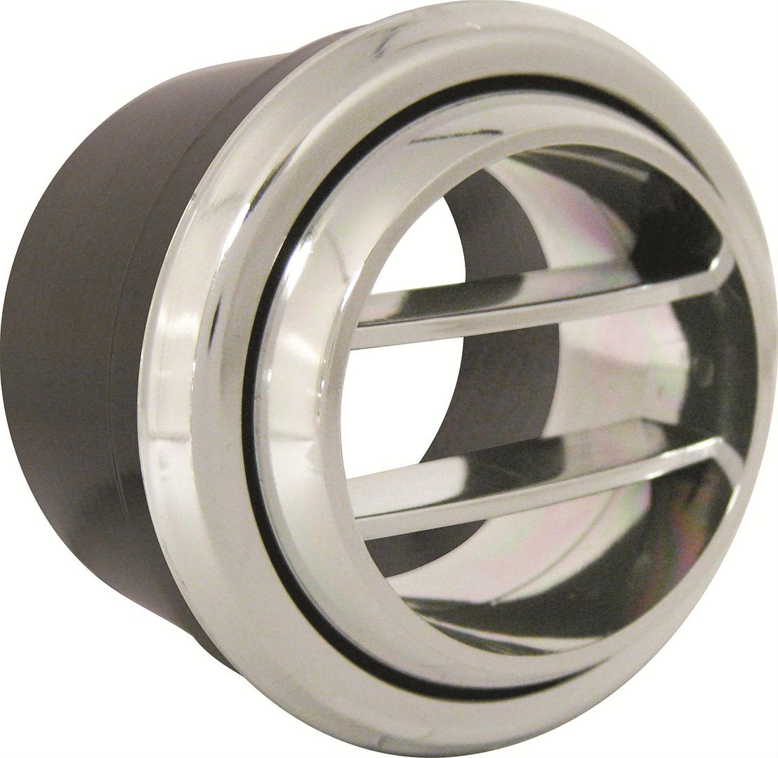
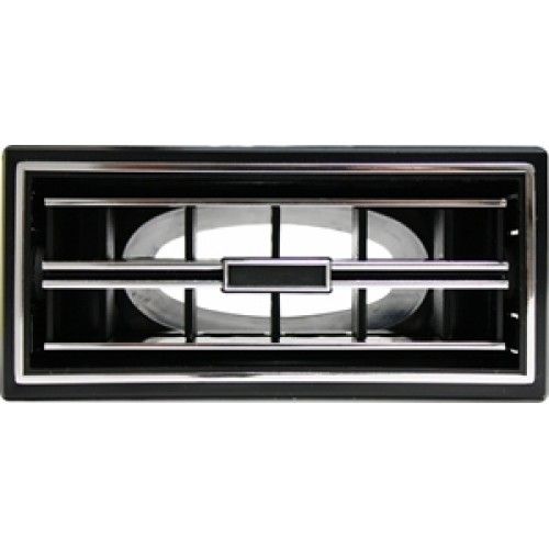
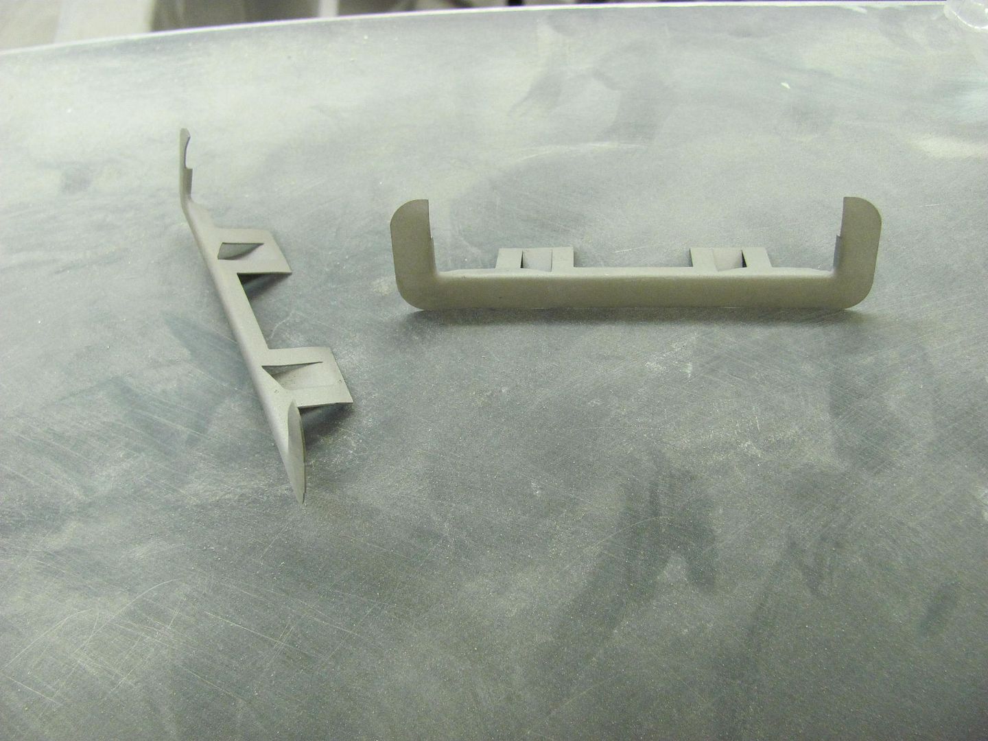
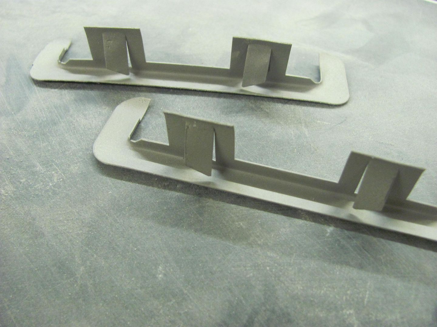
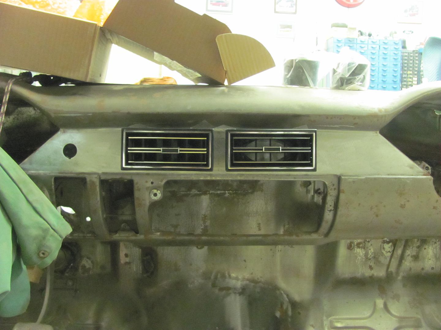
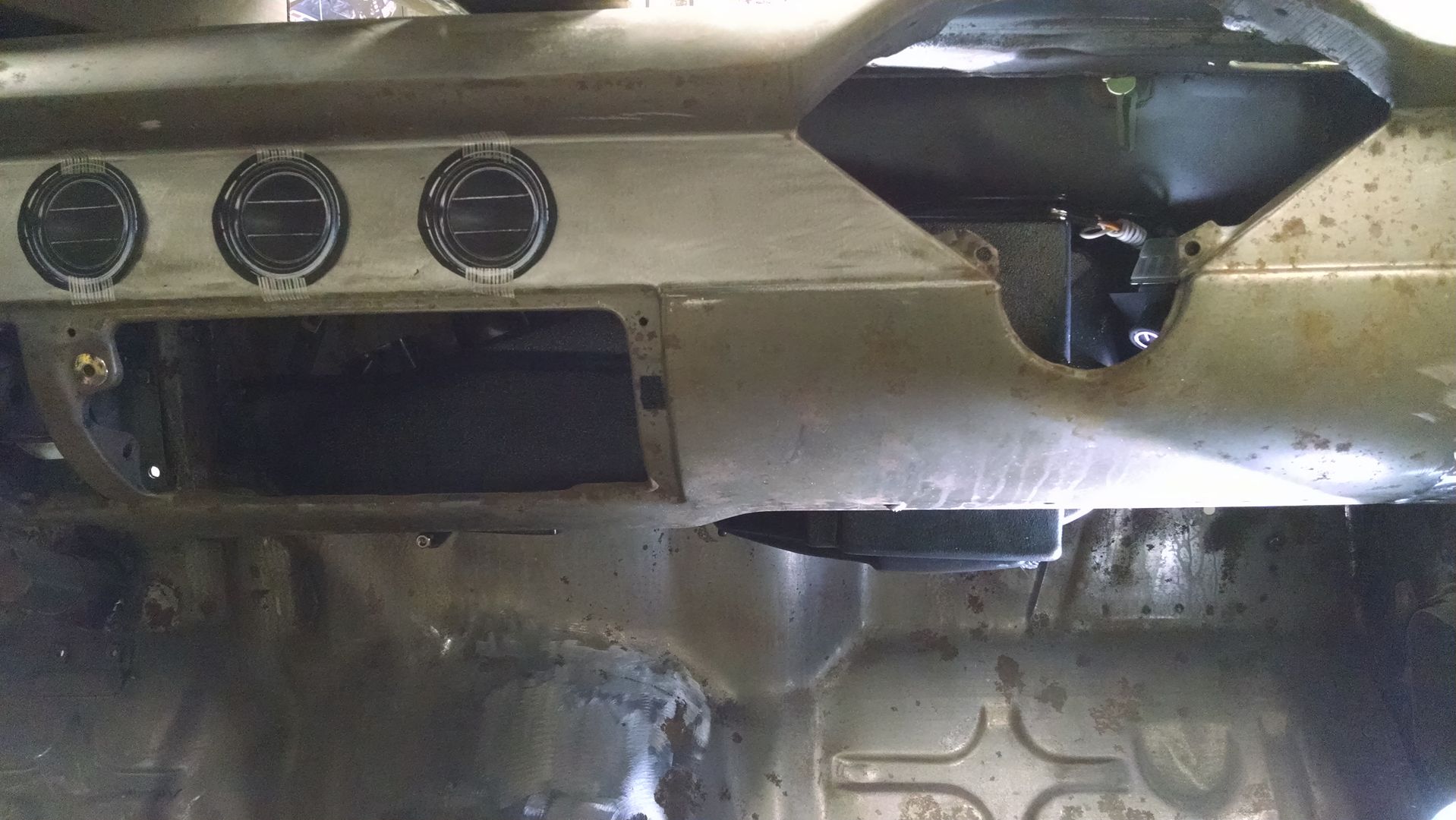
Contemplating dash vents, and I'll have to agree that these shoebox cars lend themselves more to curves, but given the long, flat, rectangular mounting surface in the center of the dash, it seemed that two round vents would not begin to fill the void. Thus we were leaning toward the rectangular vents to fill the space. Dana wanted to keep the outside vents round, and mount below in the factory location. So these are the ones decided on, Vintage Air pieces...


for the corner locations.....

Picture%202626.jpg


for the center of the dash.......

Picture%202627.jpg


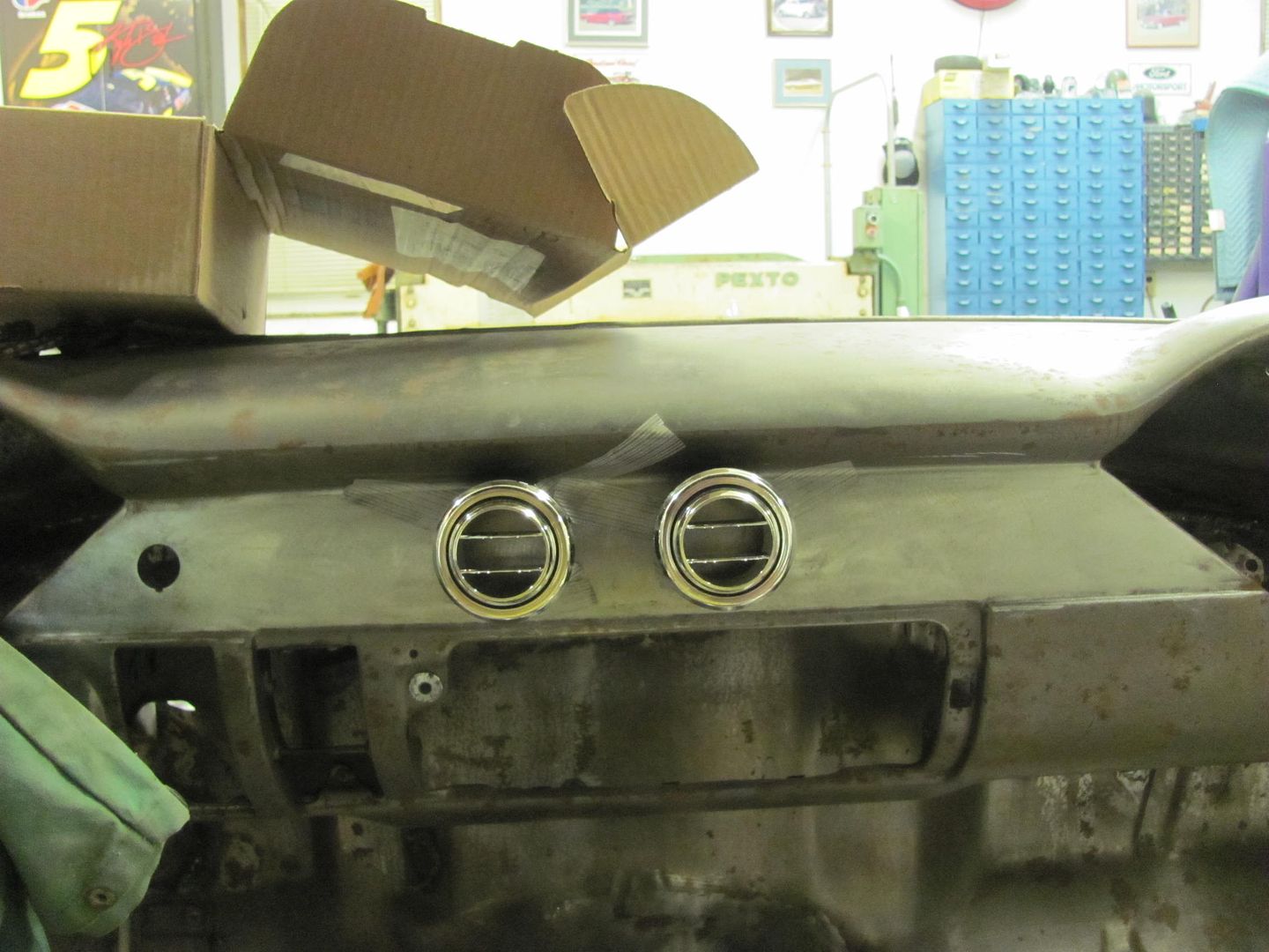
Of course, something told me to keep looking, and as someone had suggested to do the Google image search on "dash vents", I skipped the catalogs this time and looked at installed vents. Then it hit me, how could I have not seen this before.....


Picture%202625.jpg


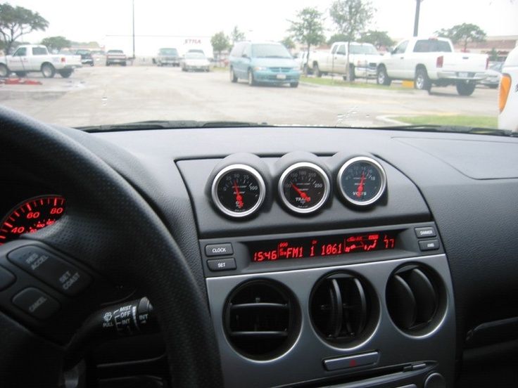
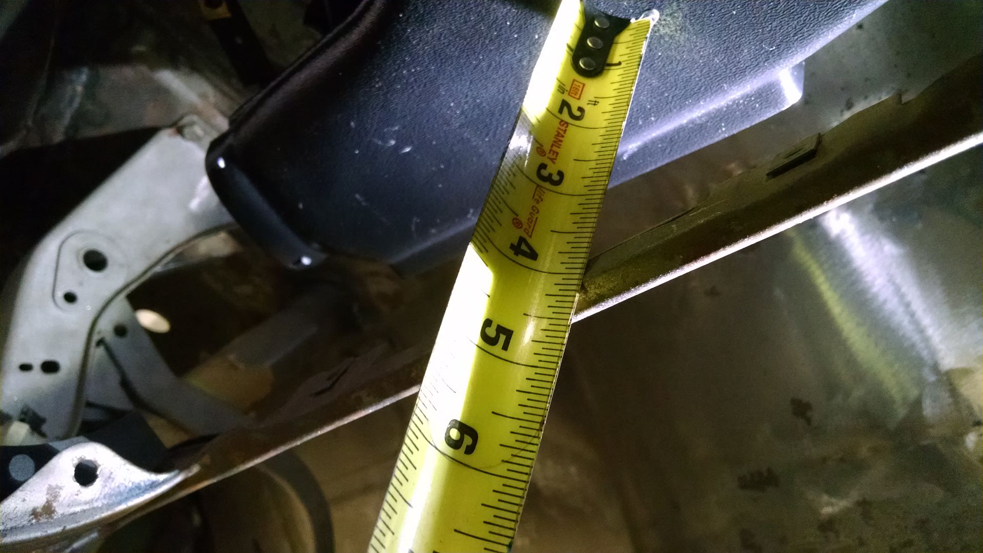
Three wide in the round vents vs. only two did a better job of filling out the dash and would give us matching vents all around. So, with only two round on order (and two rectangular that will likely go back), we plan to see how "tight" these 2-5/8 round bezels look on a 2-3/4 high flat area, and make the final decision from there.. The saga continues..


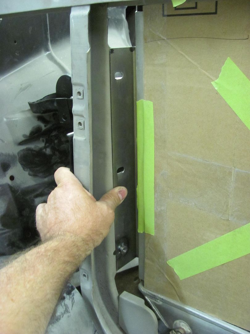
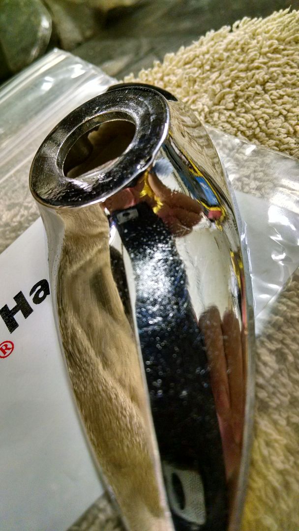
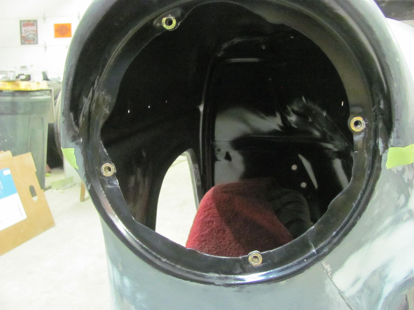
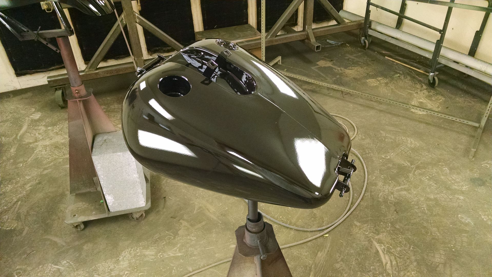
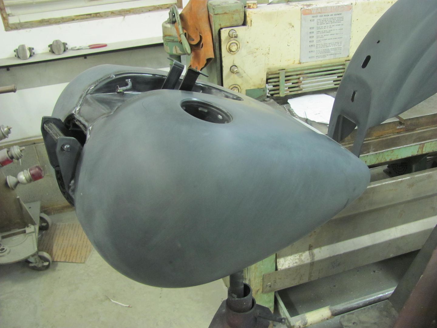
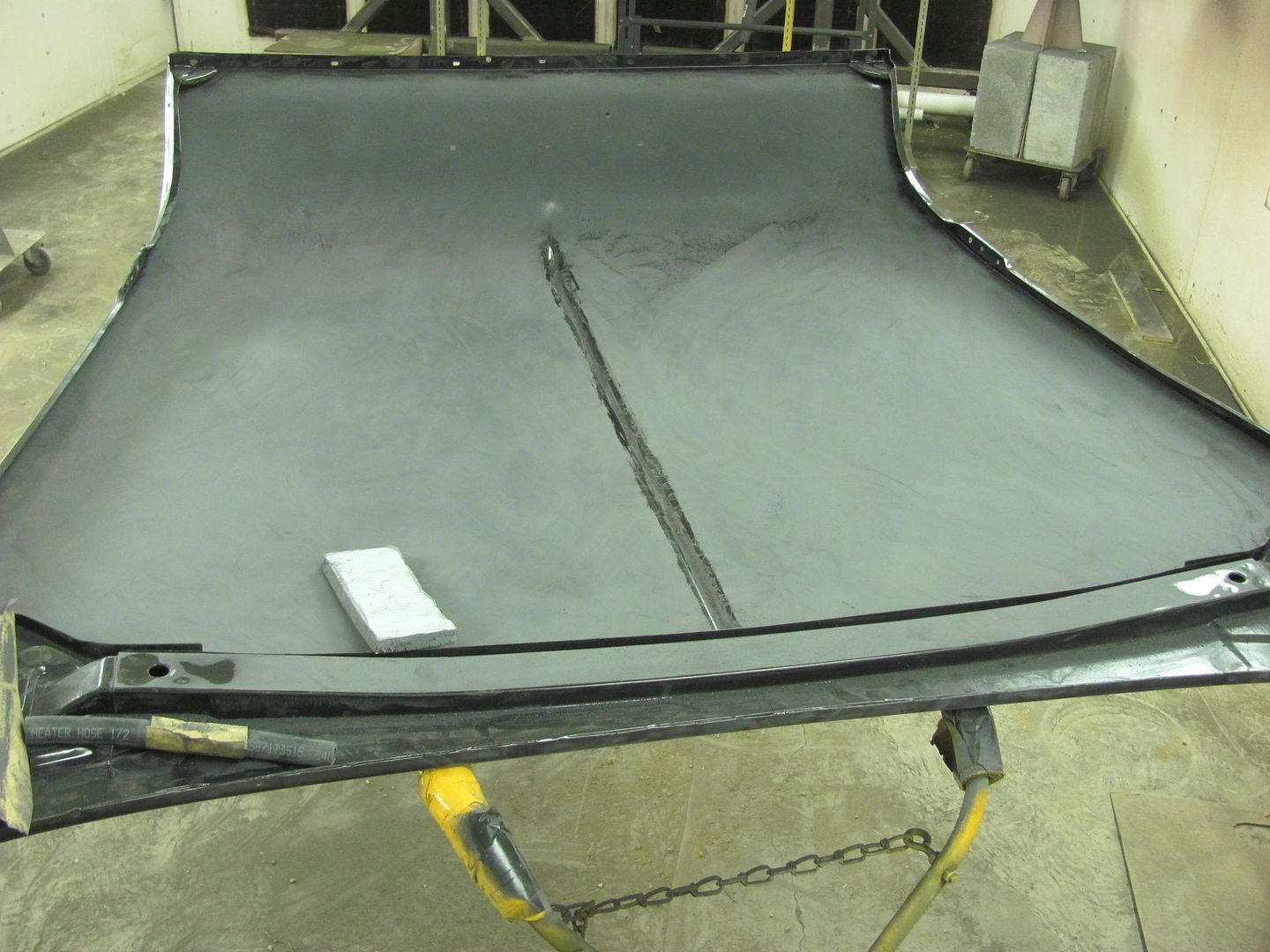
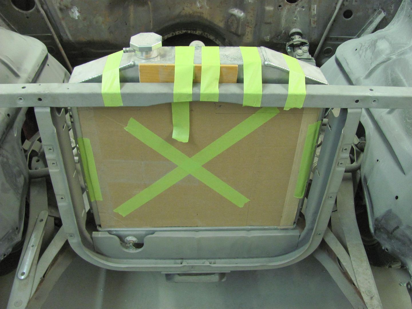
Now with the dash seams all welded and waiting for gauges to be delivered, the moment I've been dreading. Installing the Rocky Hinge fuel "door". First thing noticed was that some of the holes on the weld-in mounting plate were off by half a hole..


Picture%202609.jpg


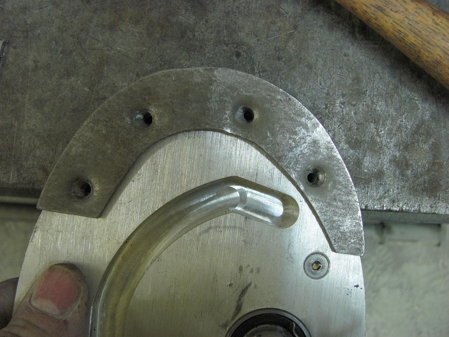
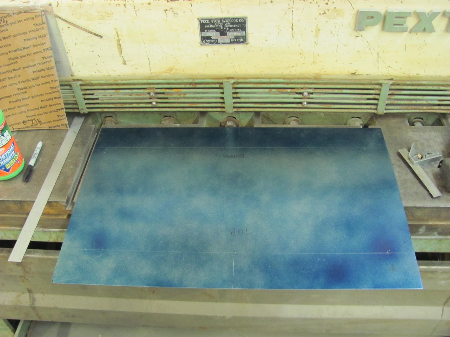
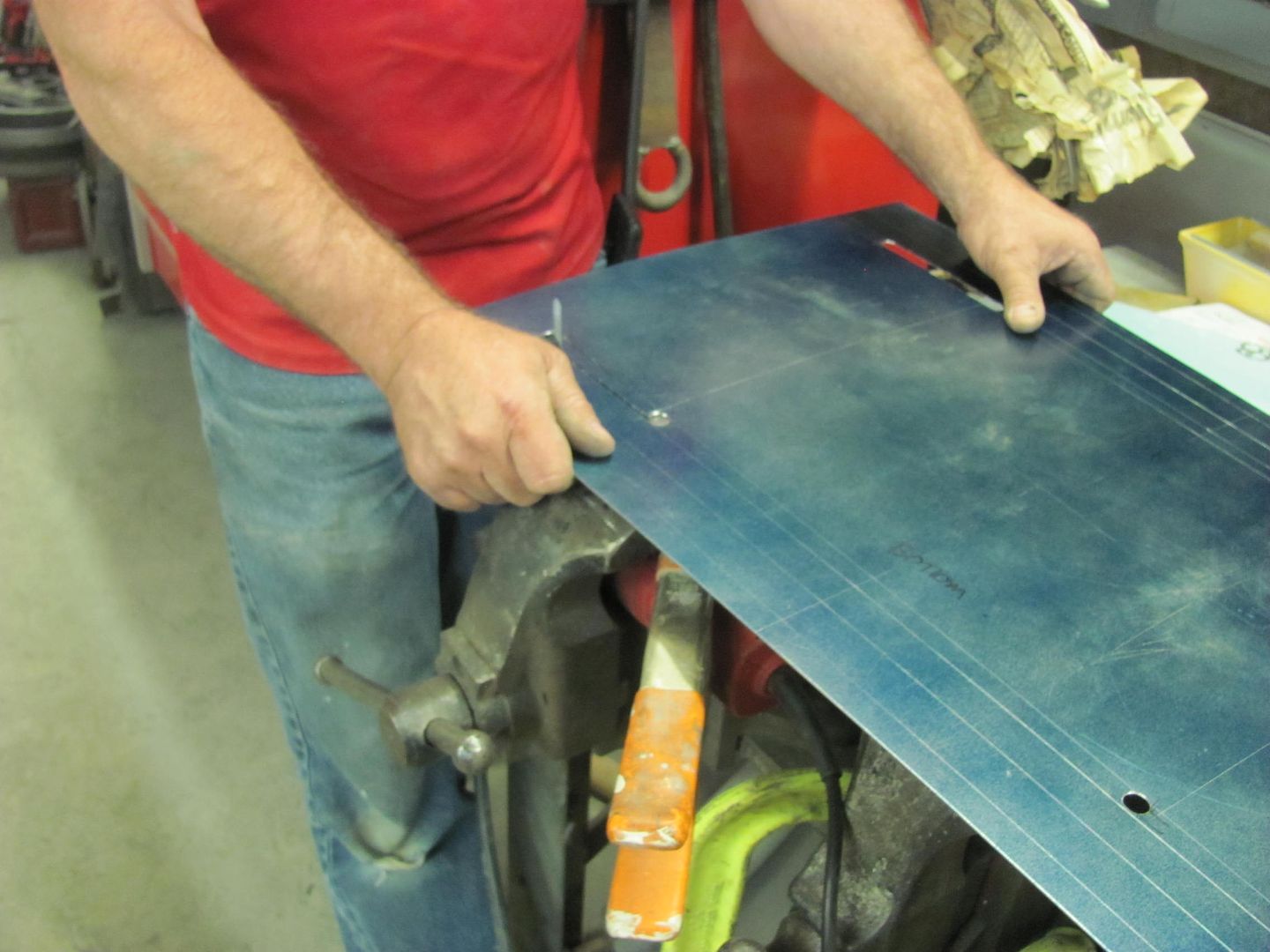
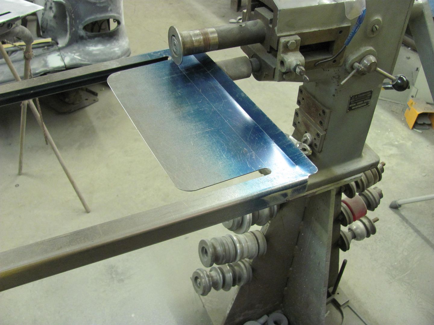
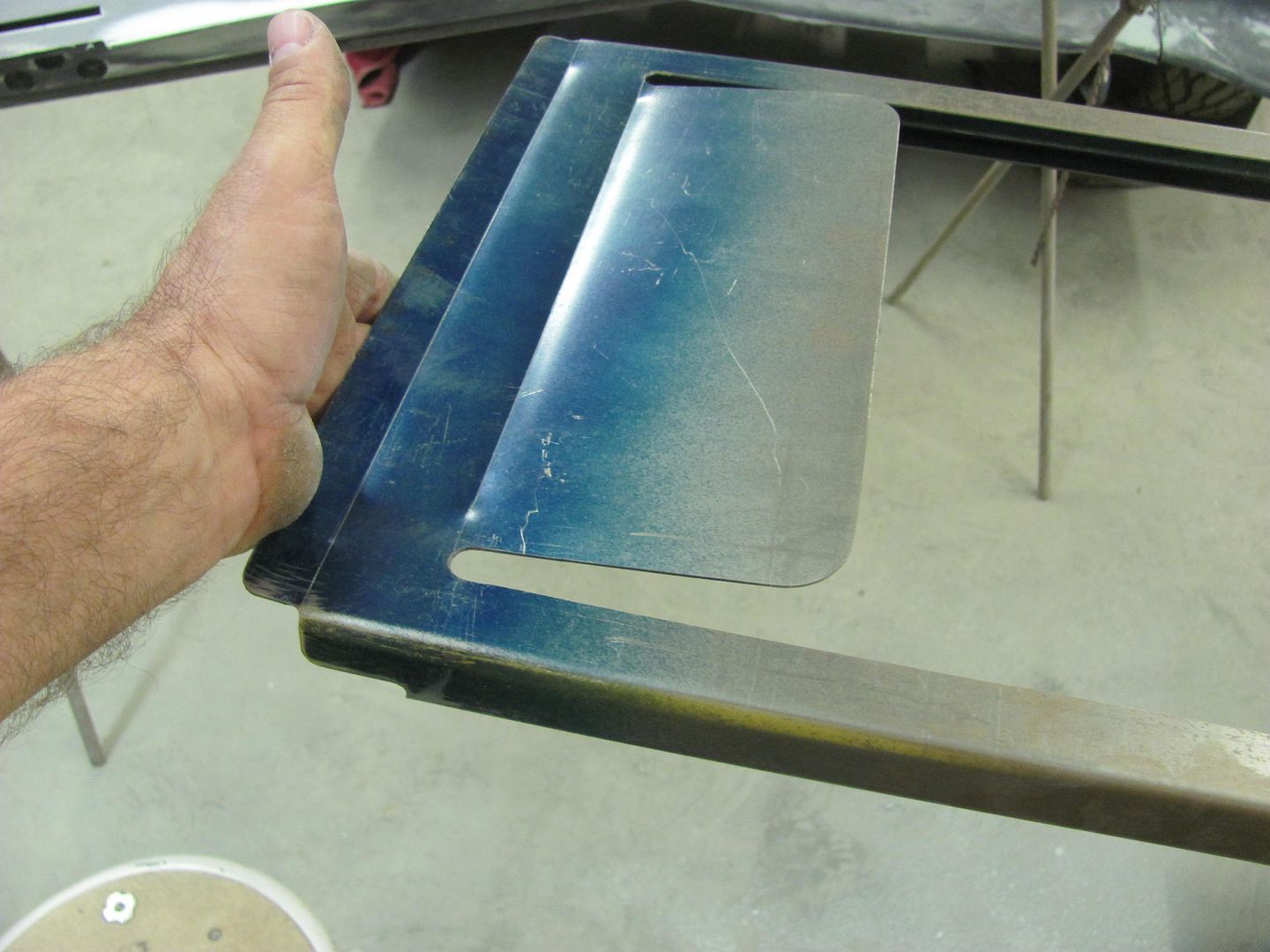
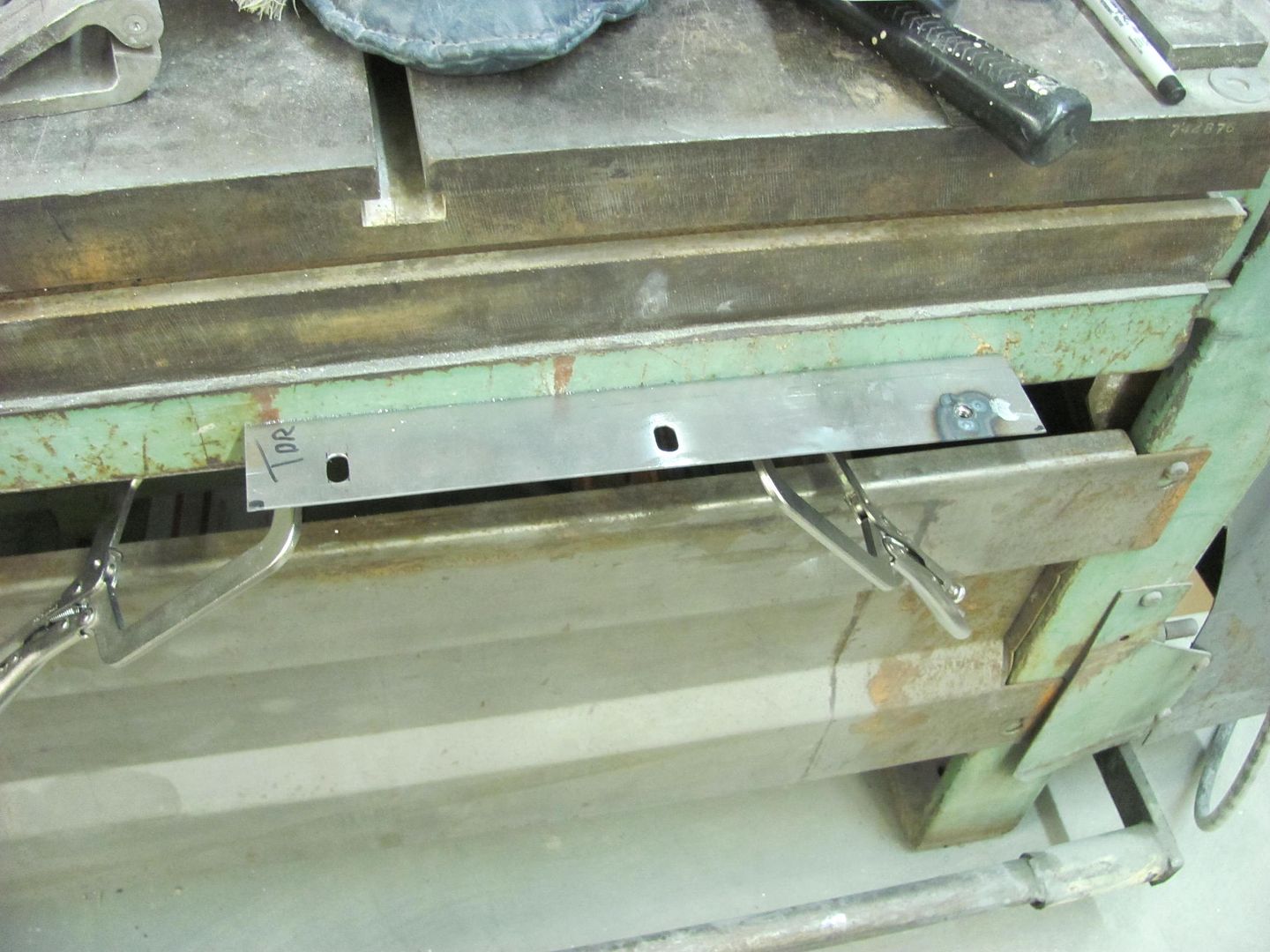
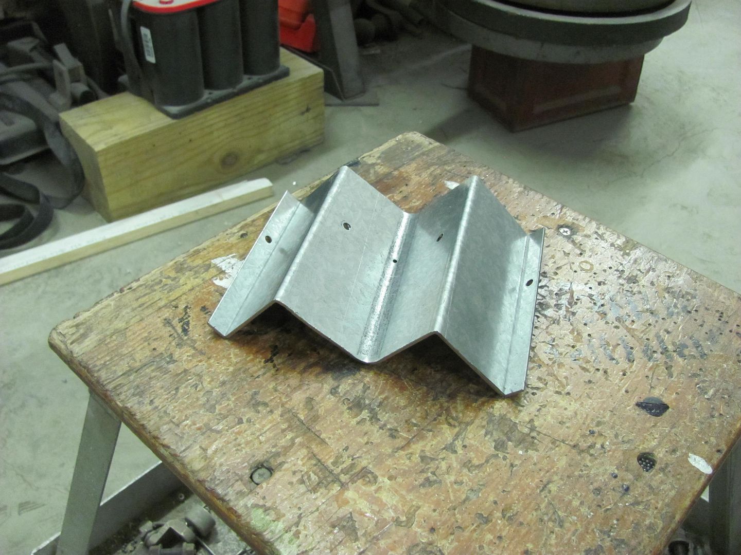
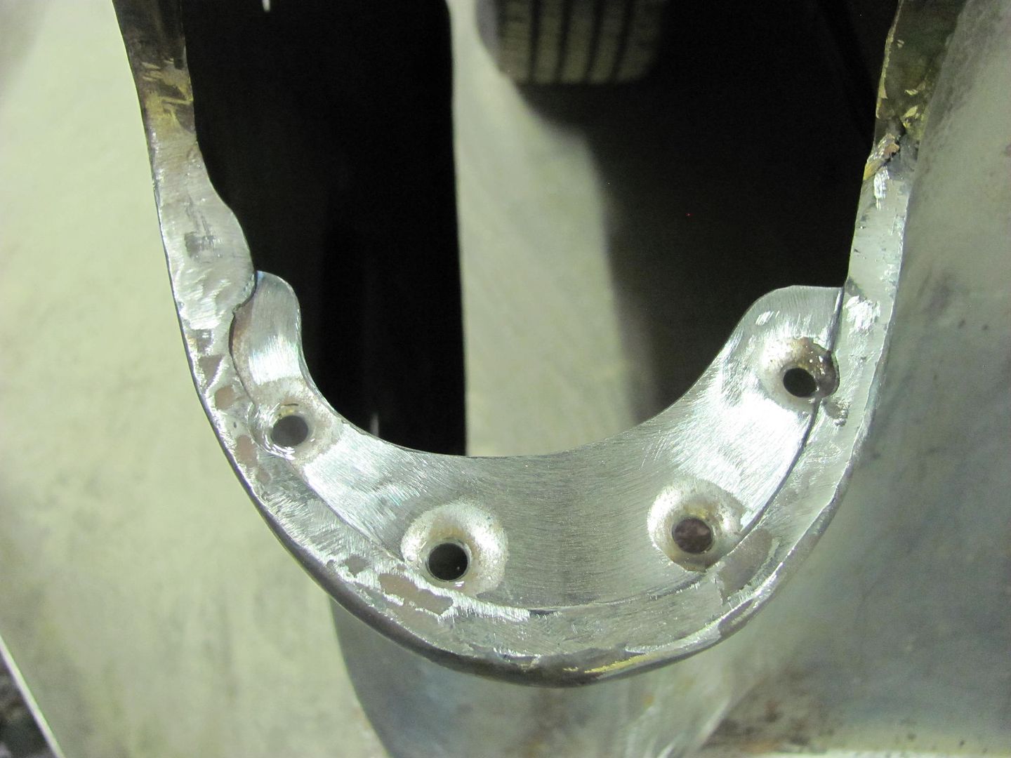
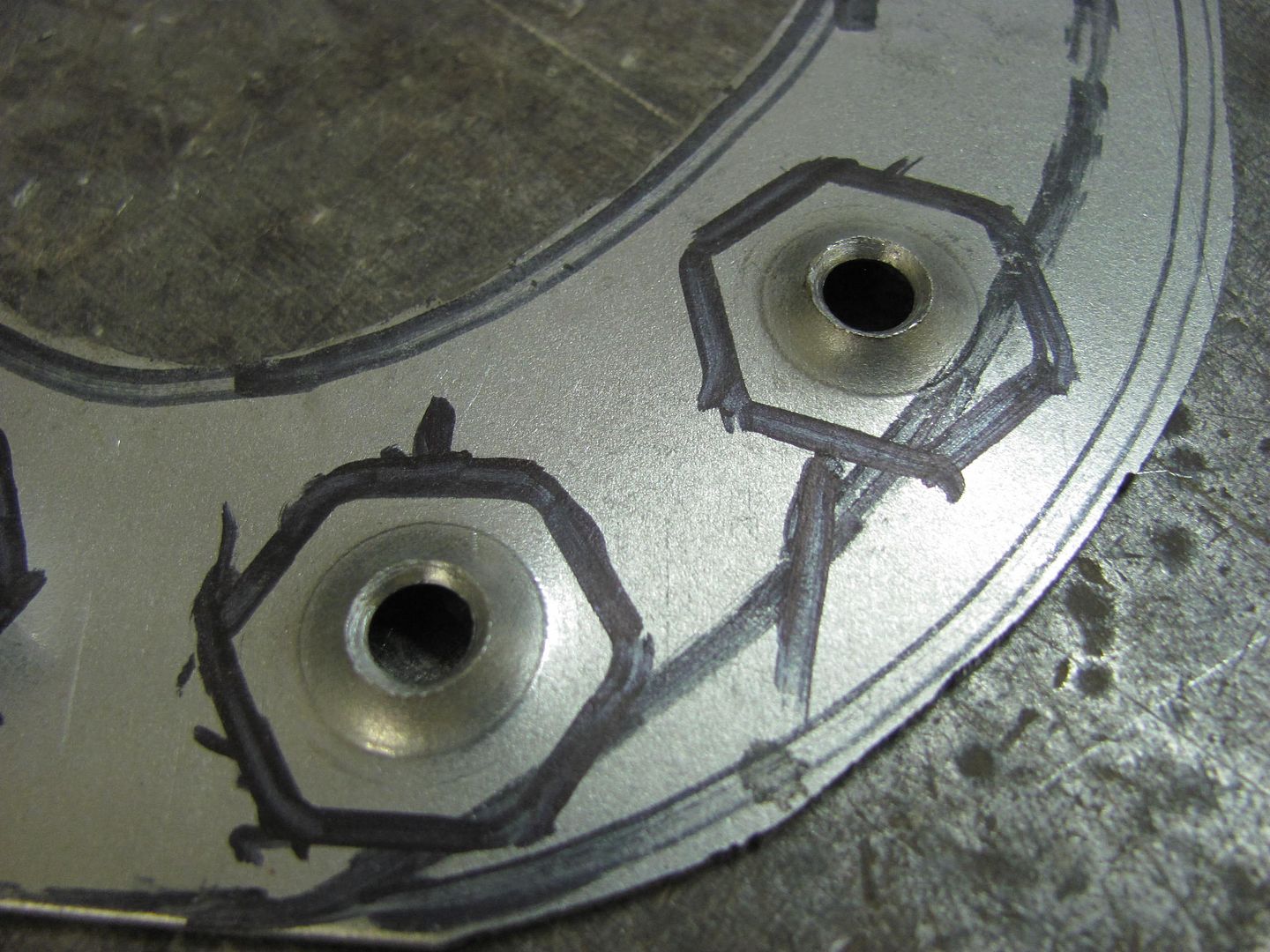
So Kyle cut out a fresh piece of 14 ga crs to make a new one, a bit oversized to trim later. Used some transfer punches to get the bolt holes lined up a bit better on our version of the weld-in plate..


Picture%202606.jpg


Picture%202607.jpg


Picture%202608.jpg


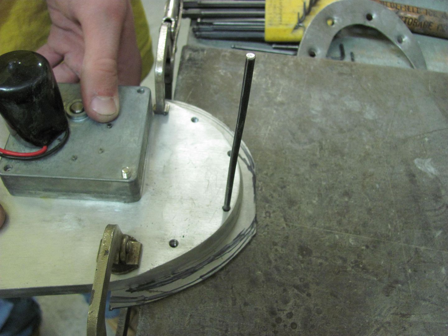
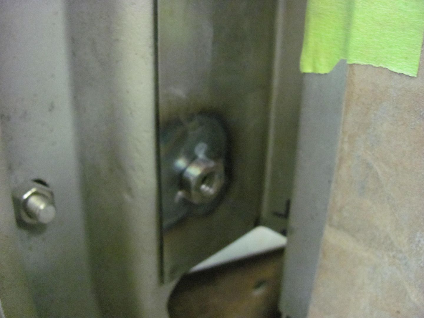
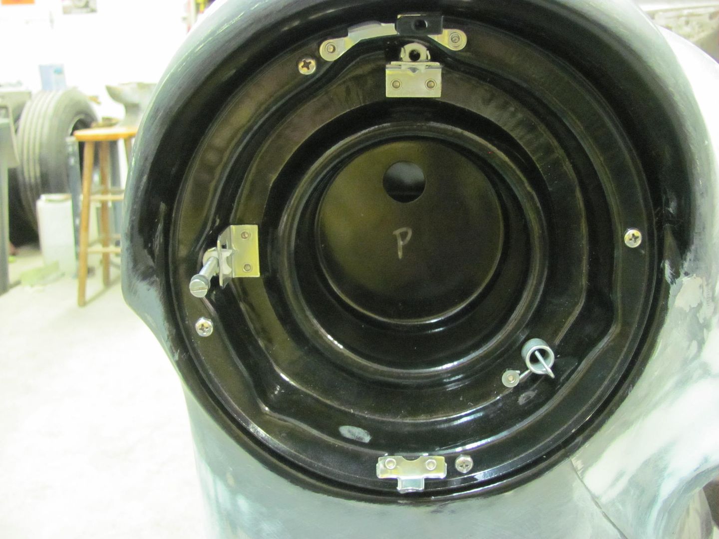
Attachment screws fitting better already....


Picture%202612.jpg


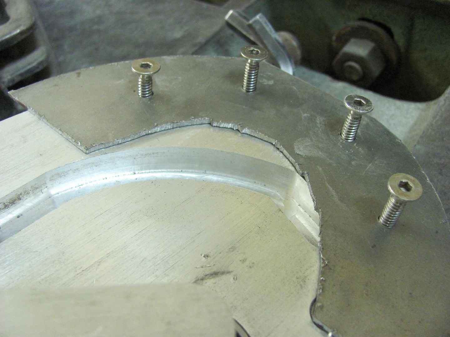
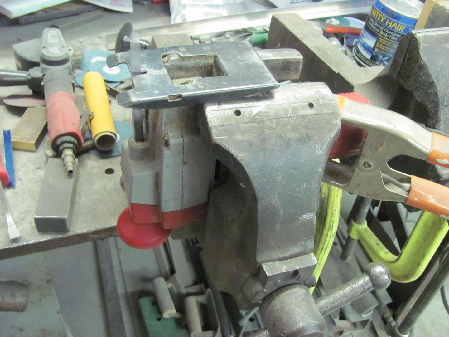
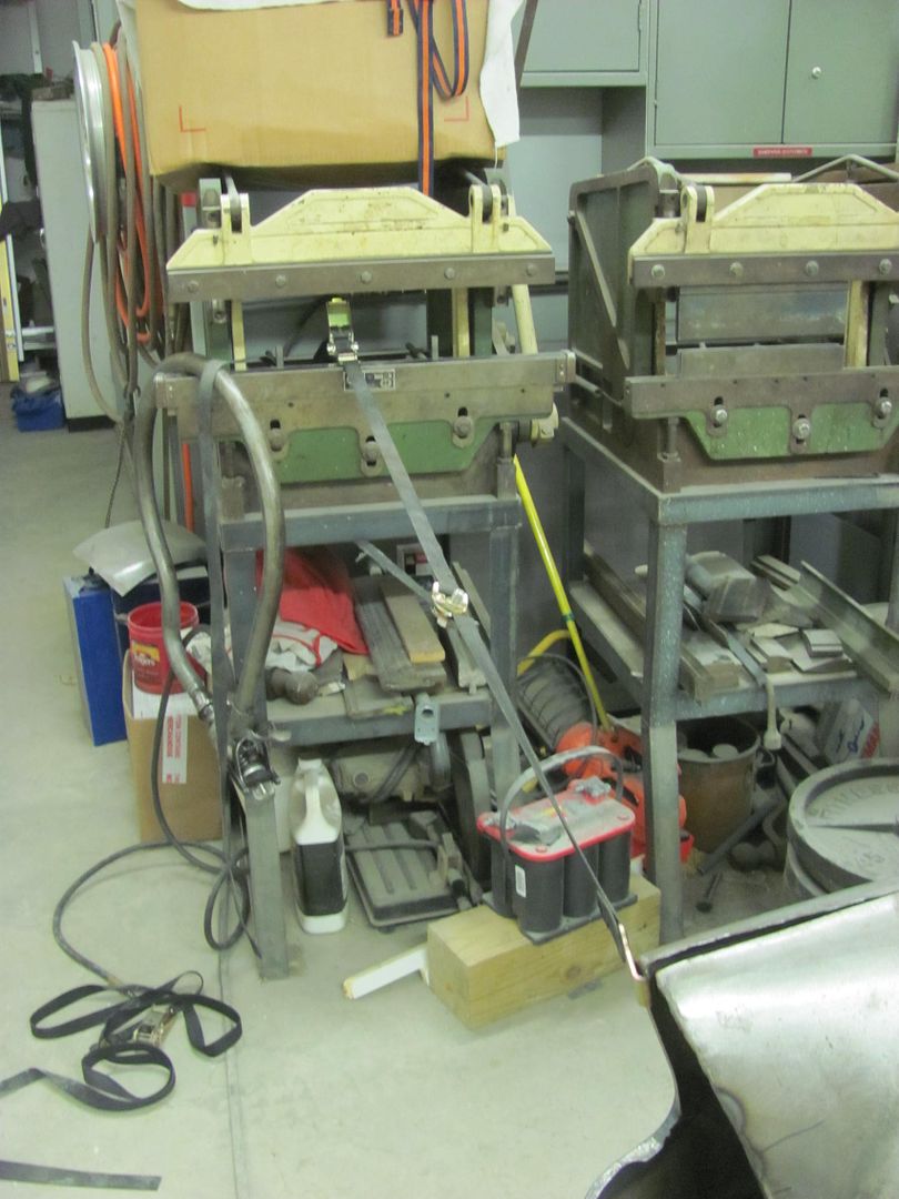
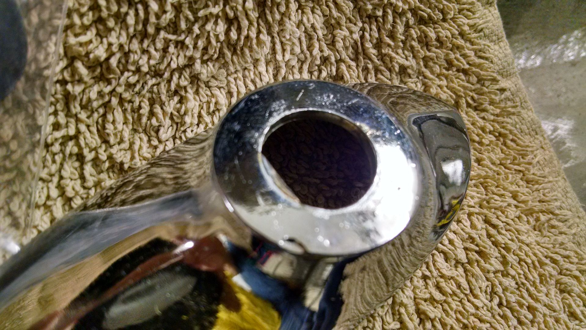
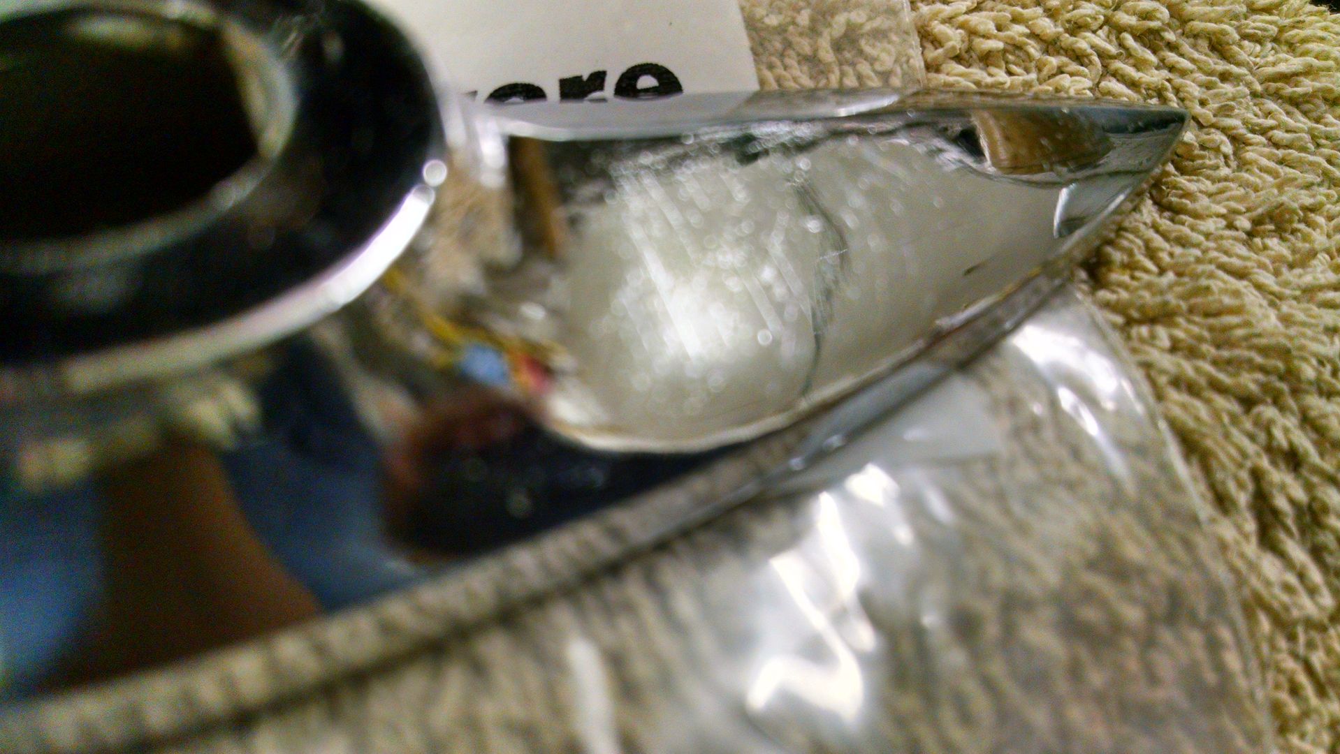
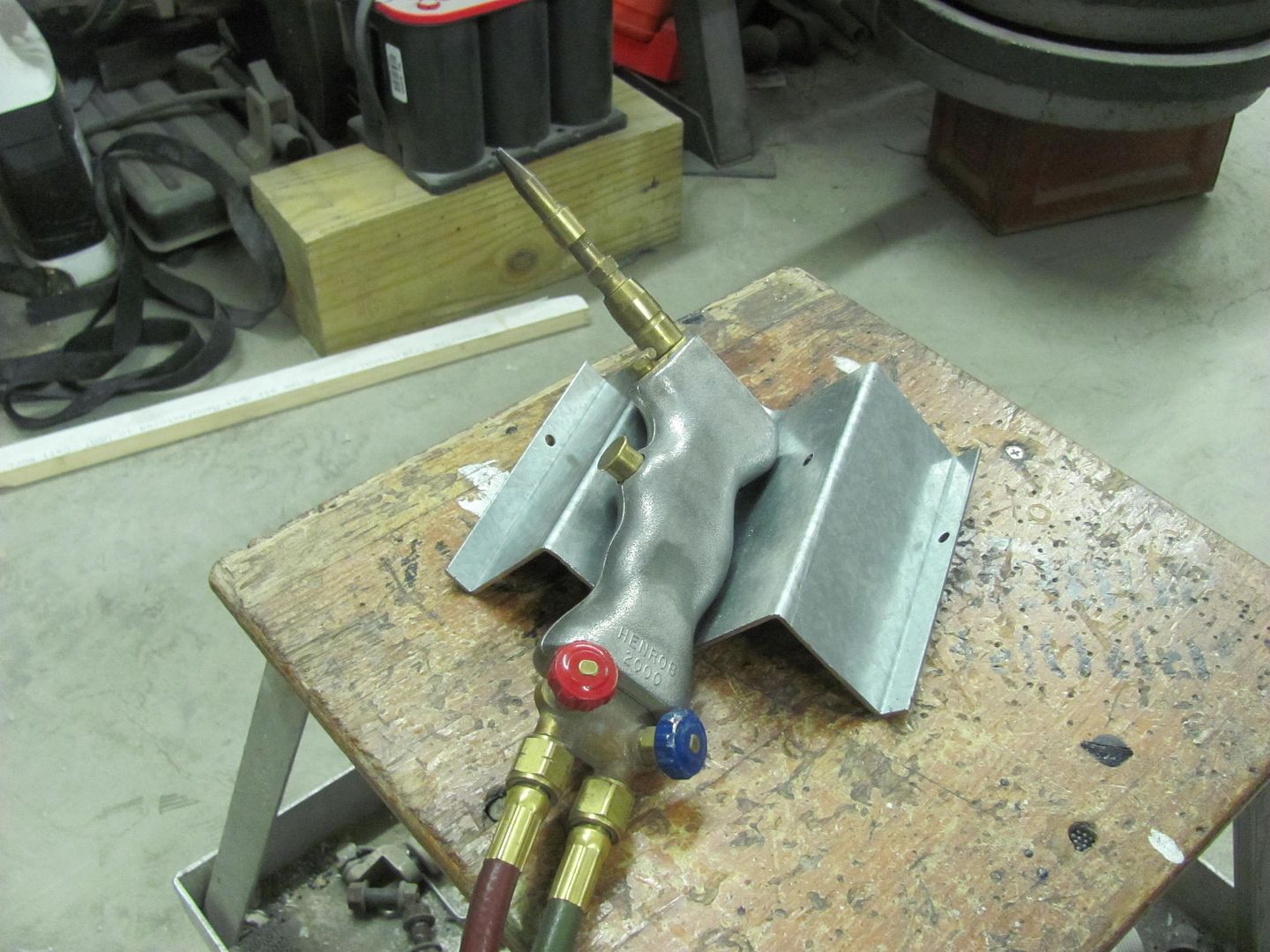
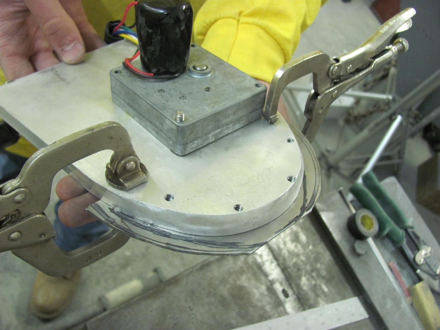
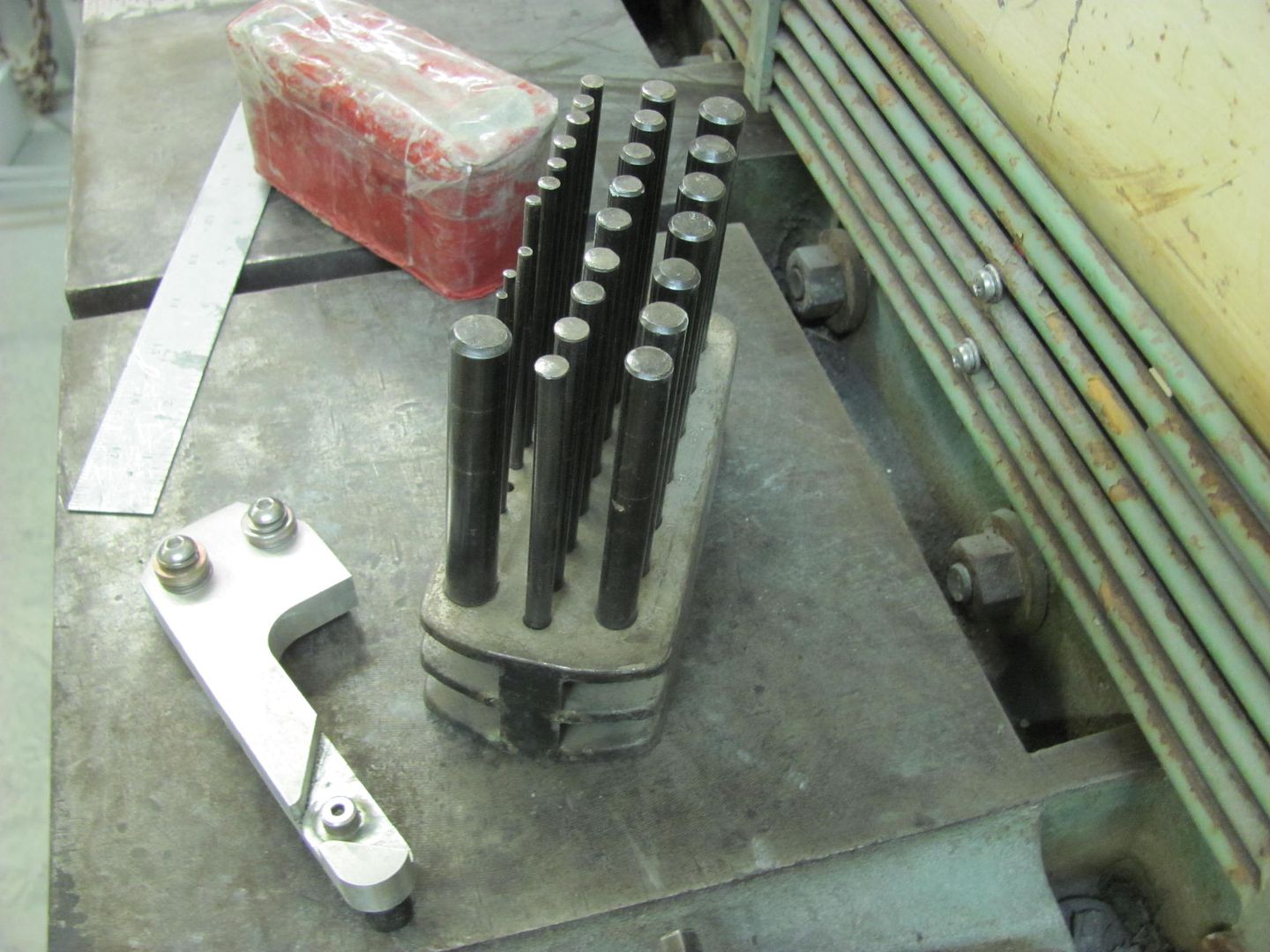
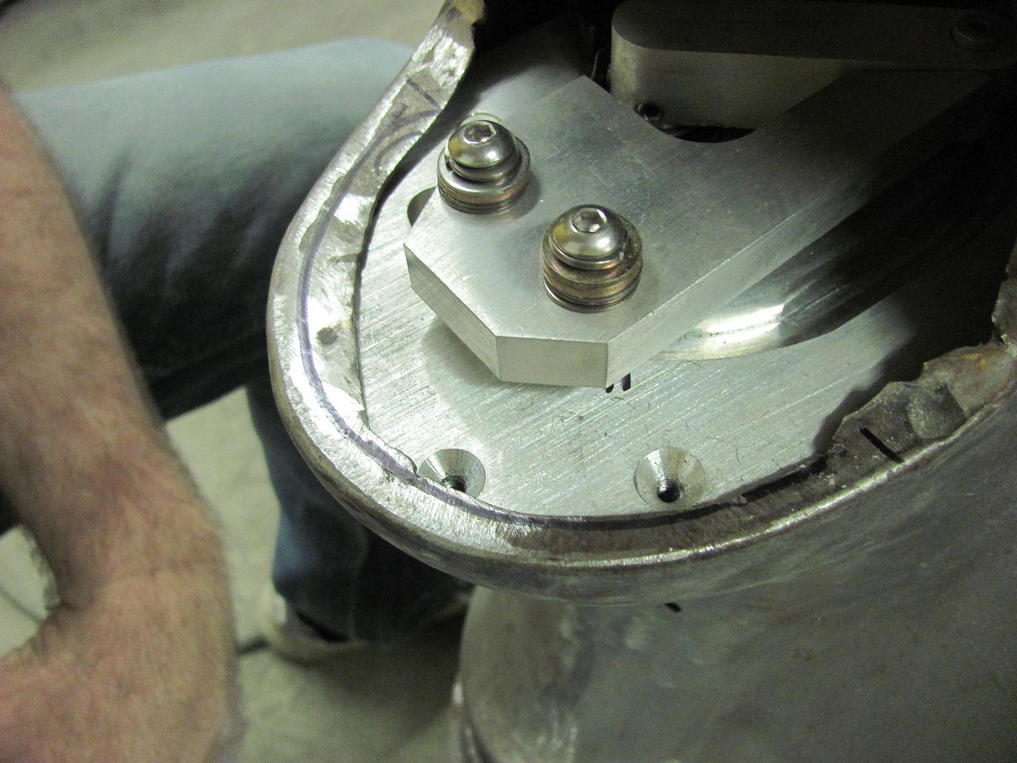
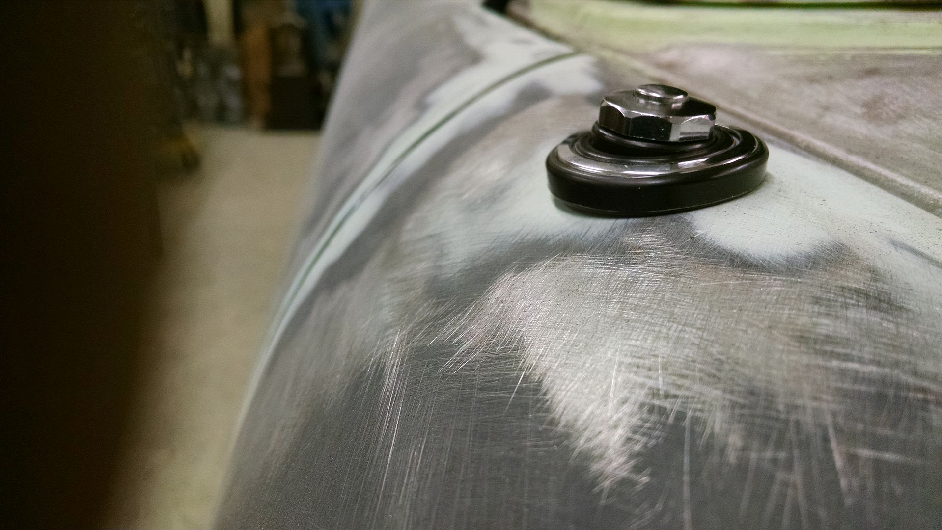
To provide the proper "pressed" countersink, we broke out the tubing flare kit...
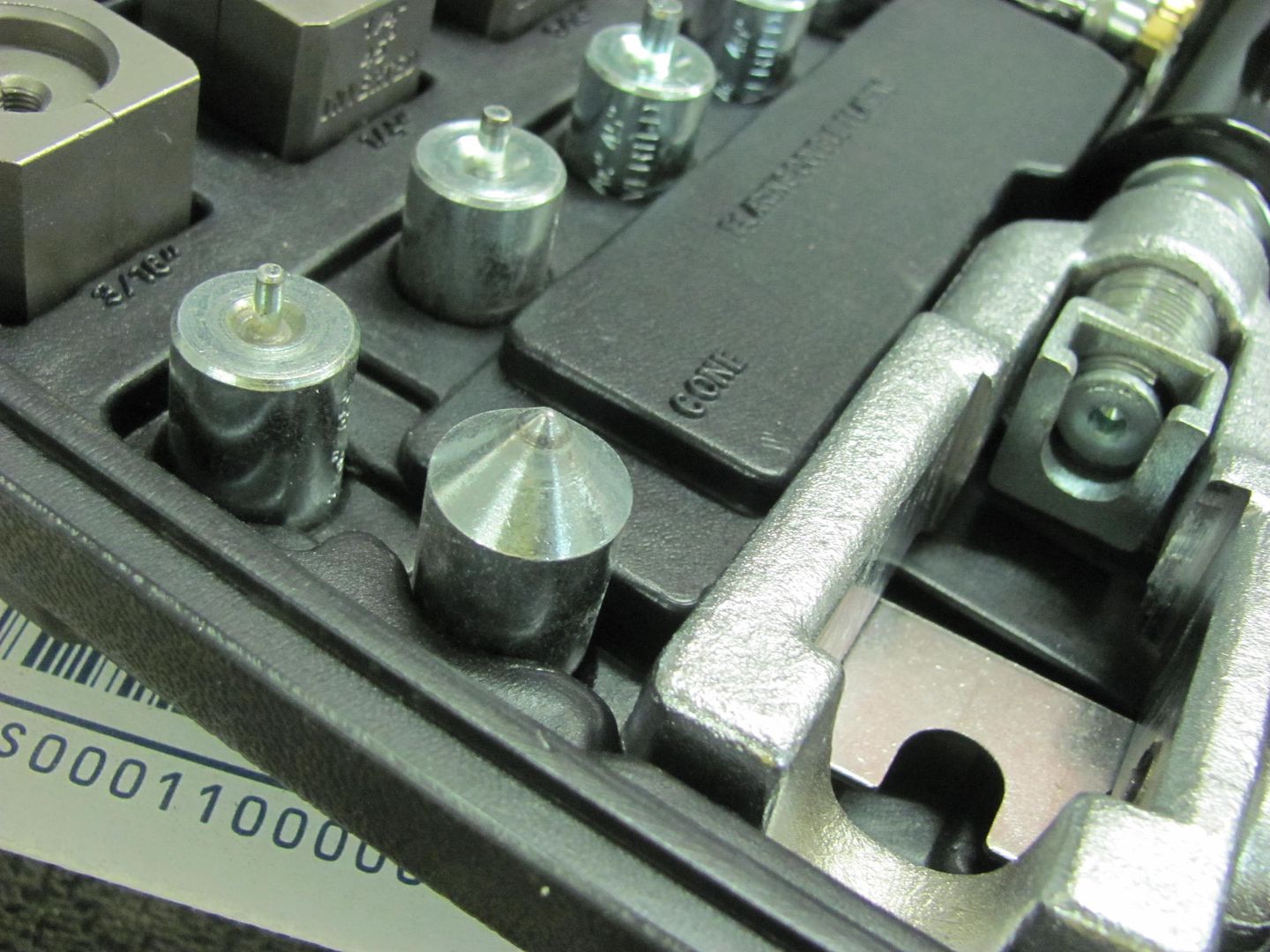
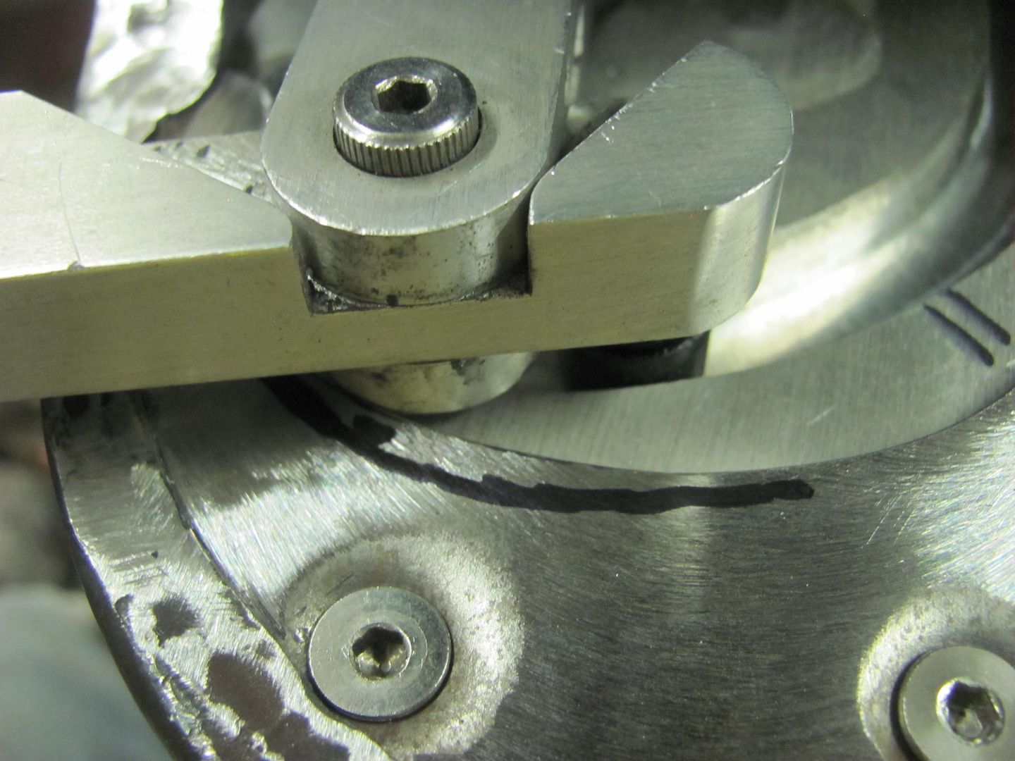

Picture%202615.jpg


Redneck press...


Picture%202614.jpg


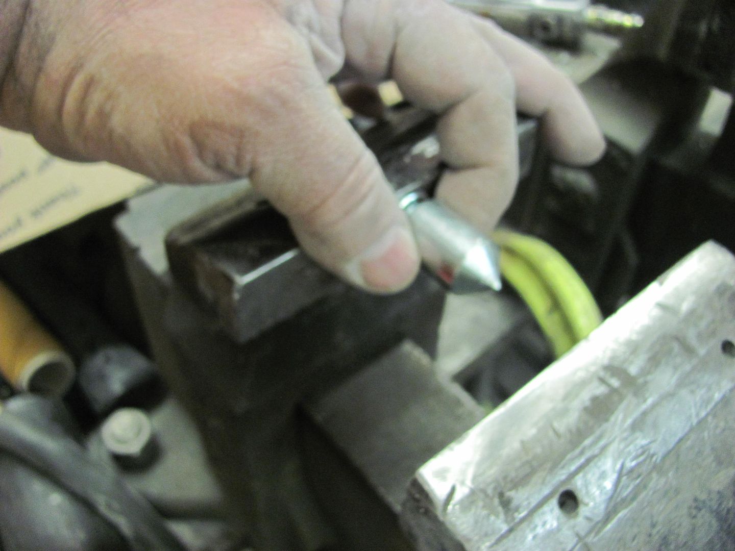
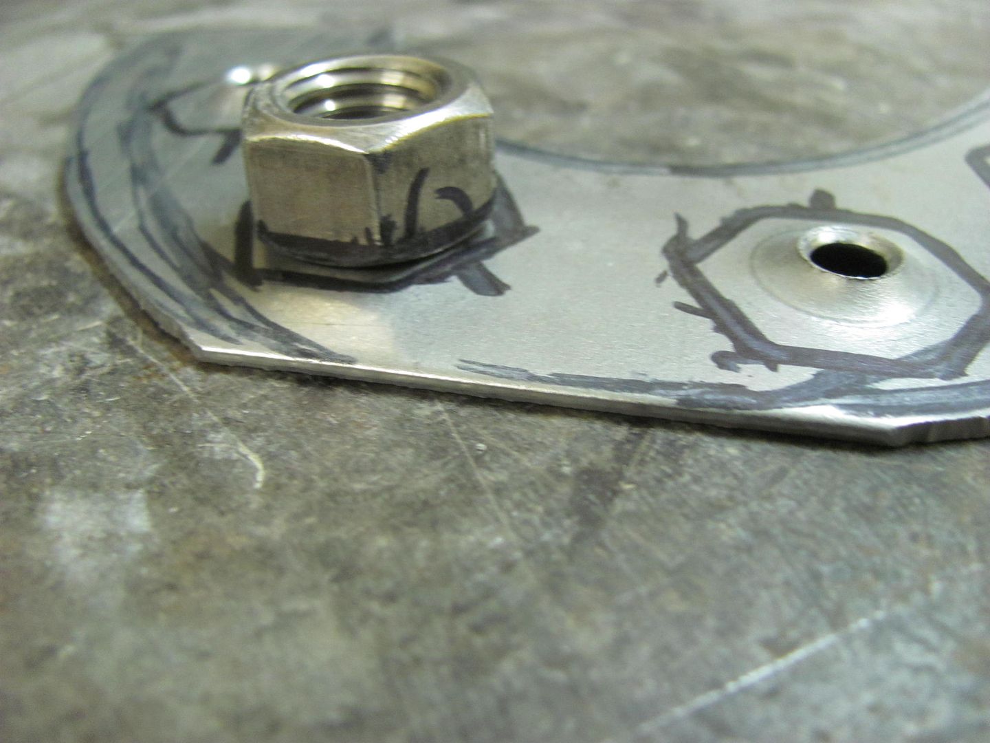
Our lower "die" was a 1/2-13 nut, centered over the hole, perimeter marked, and then taped in place before locating this into the press. Hey, it wasn't pretty, but it worked!


Picture%202616.jpg


Picture%202617.jpg


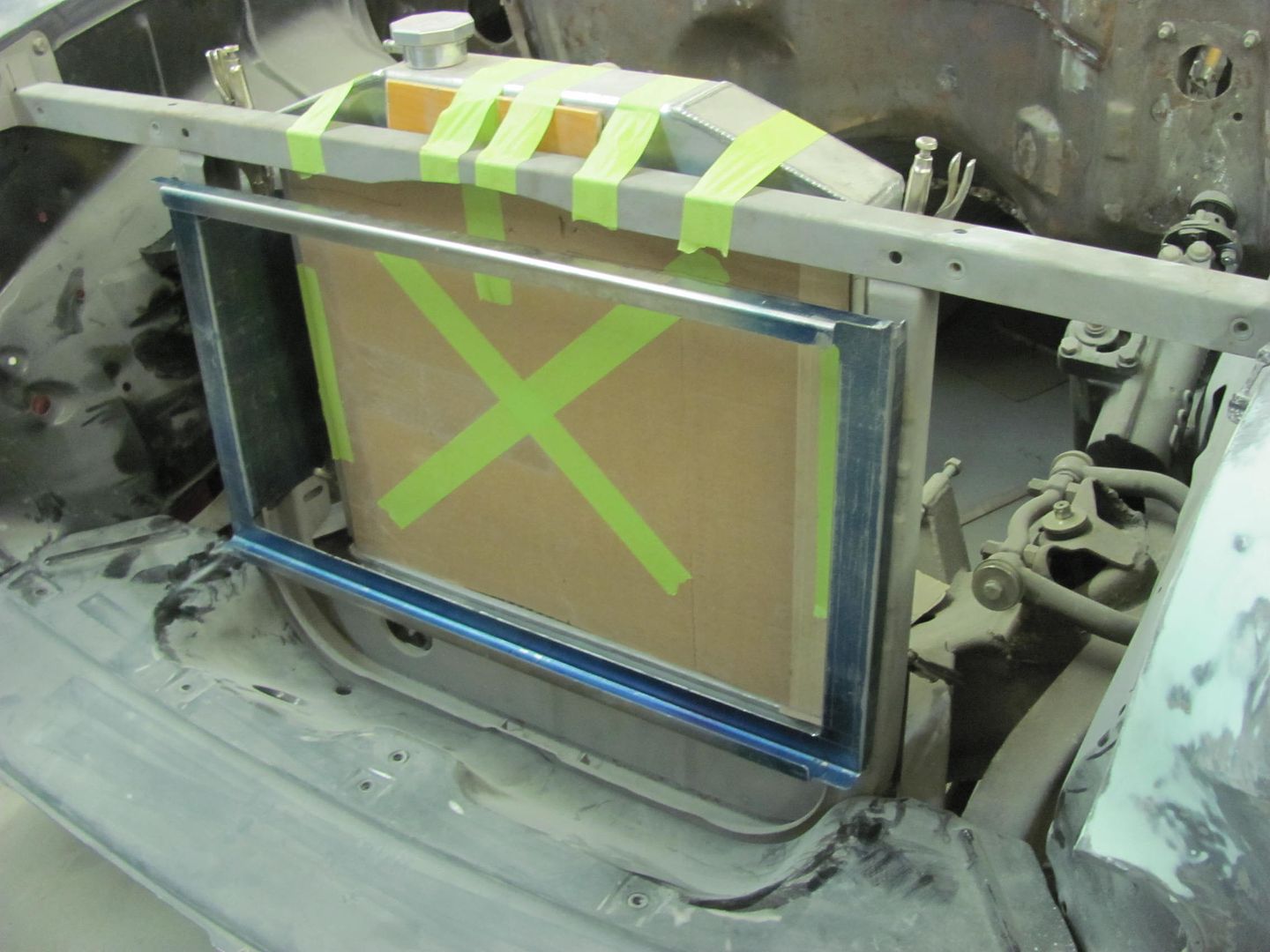
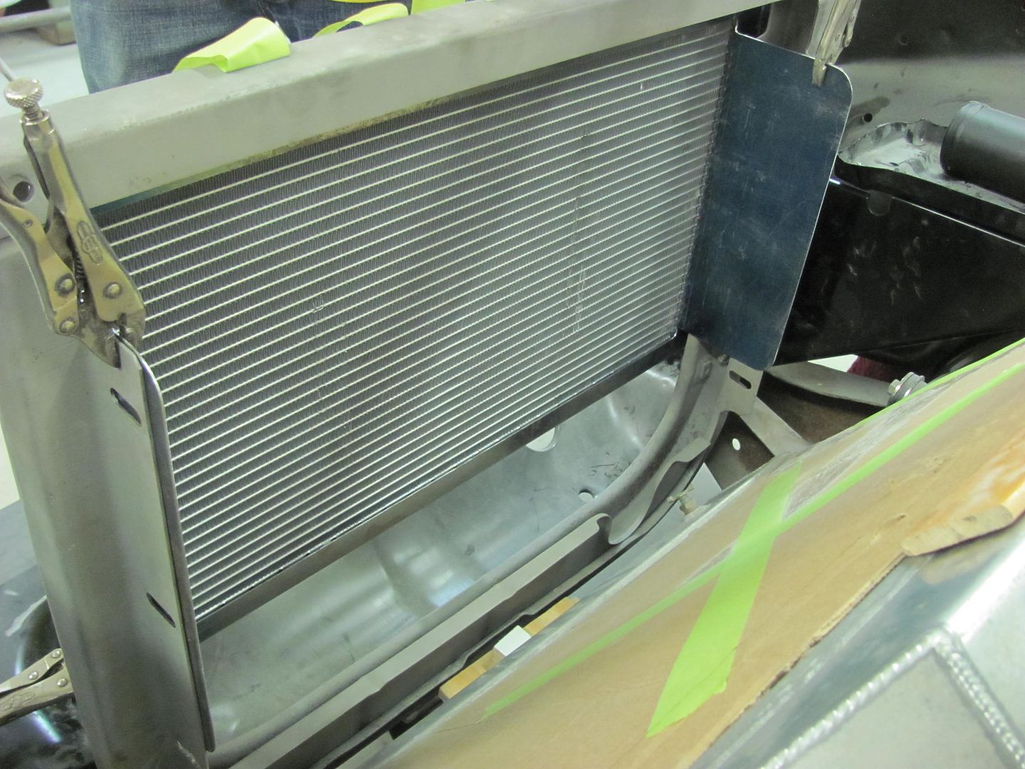
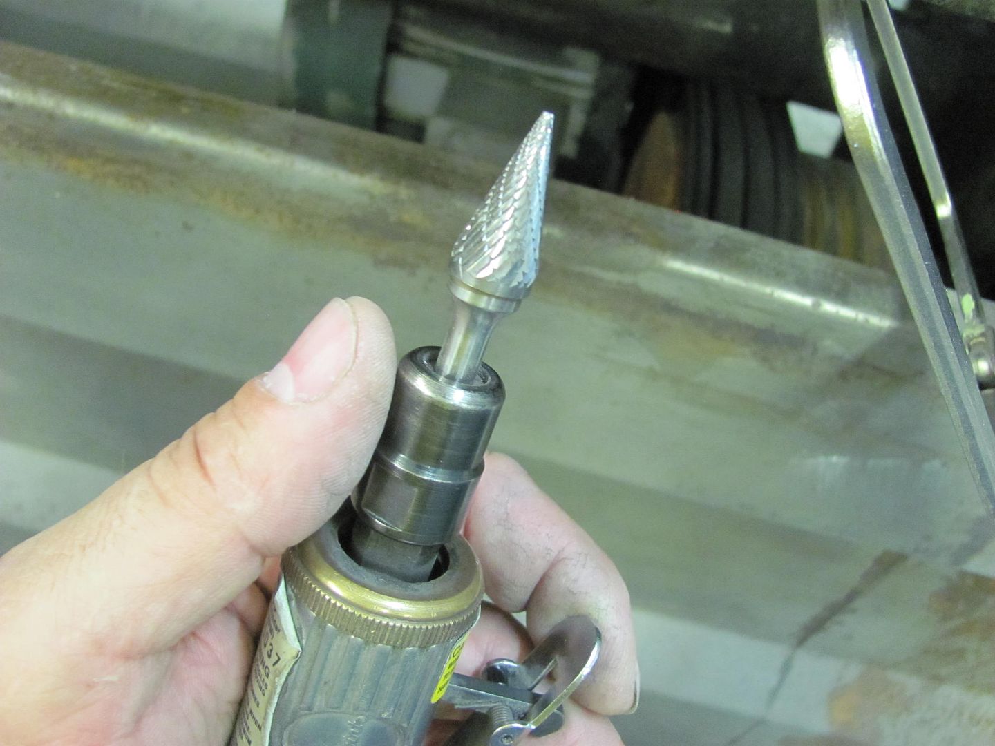
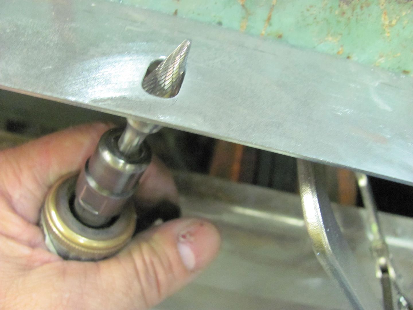
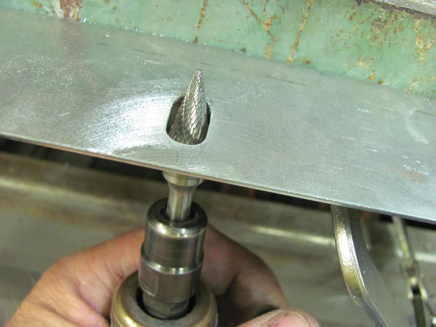
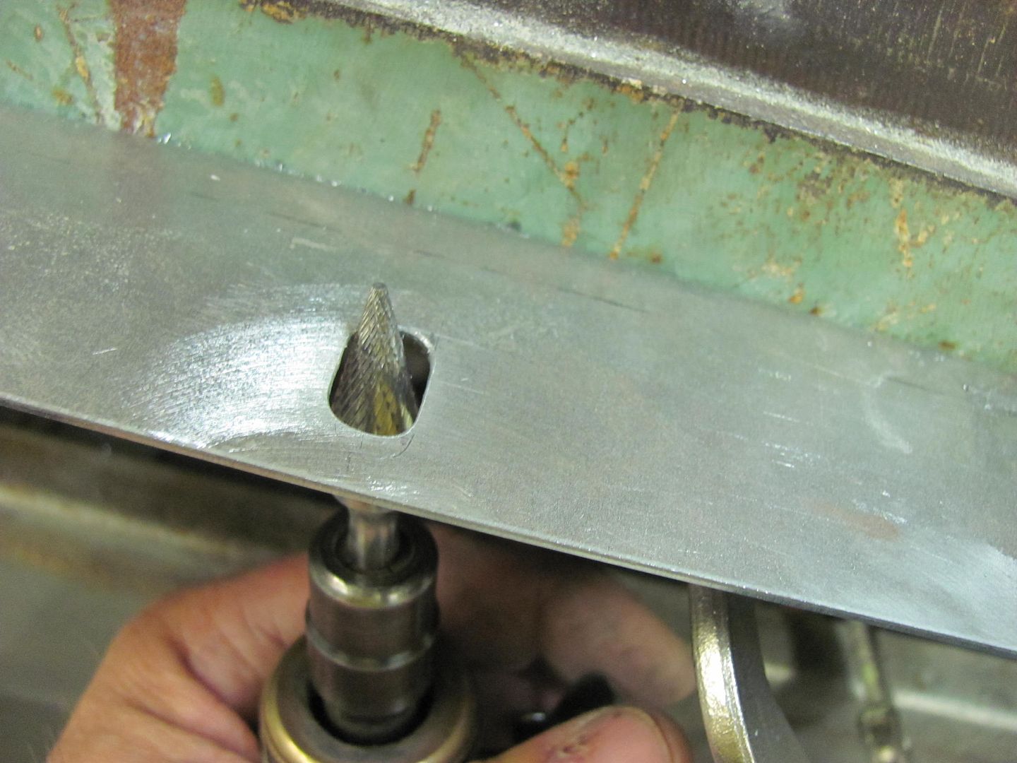
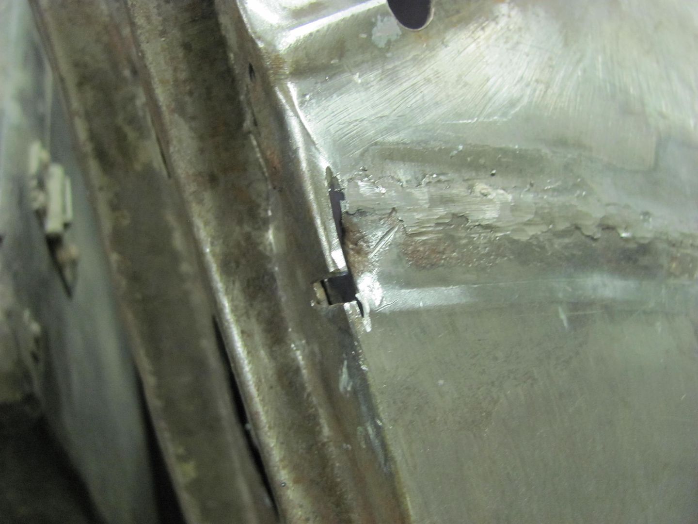
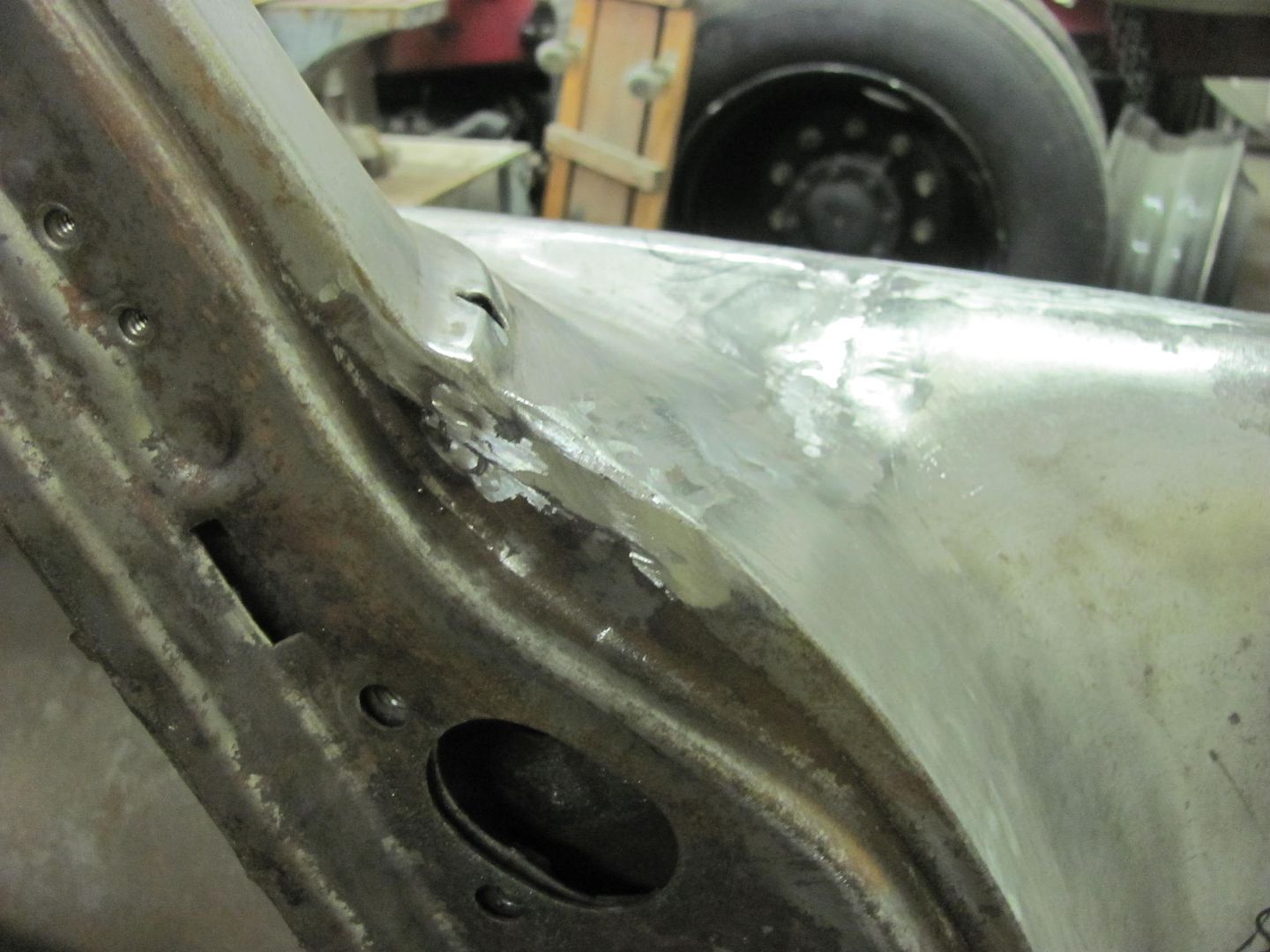
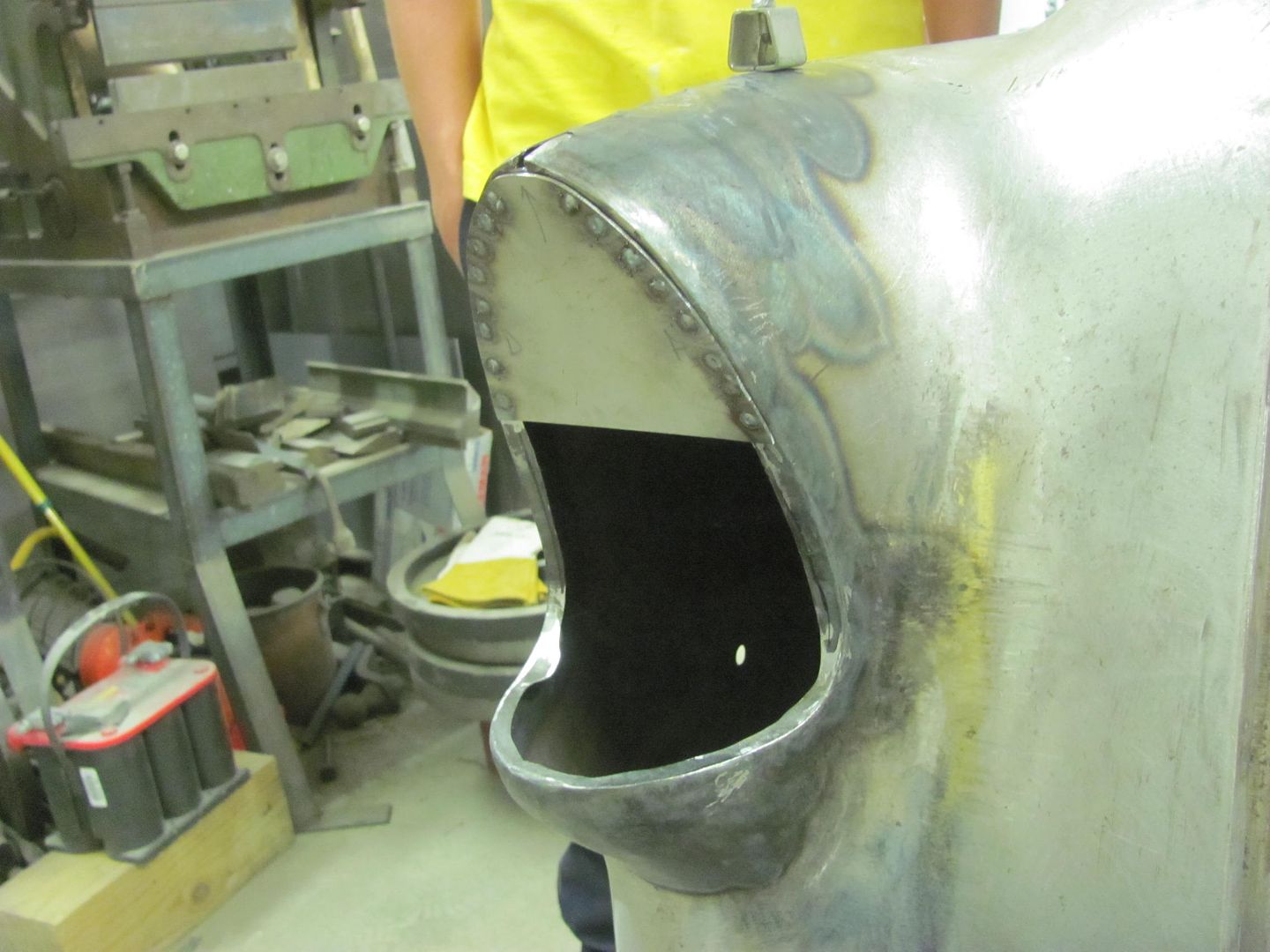
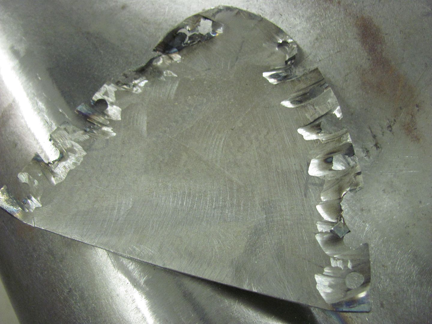
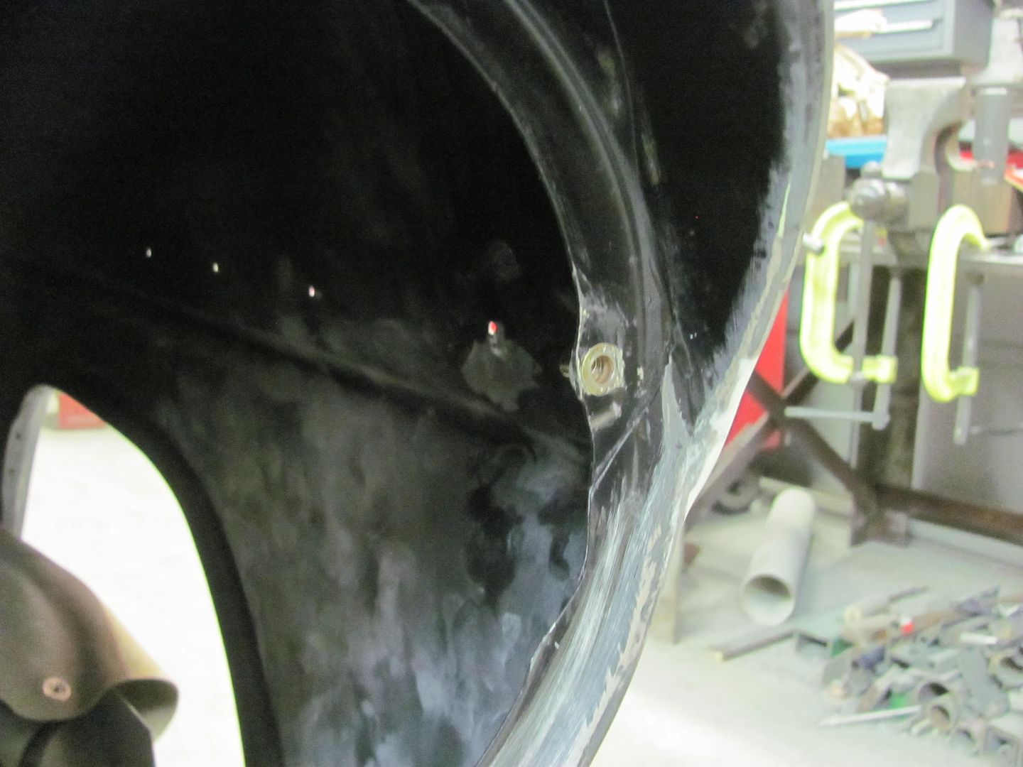
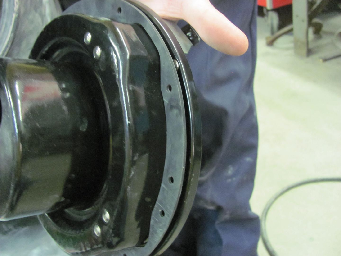
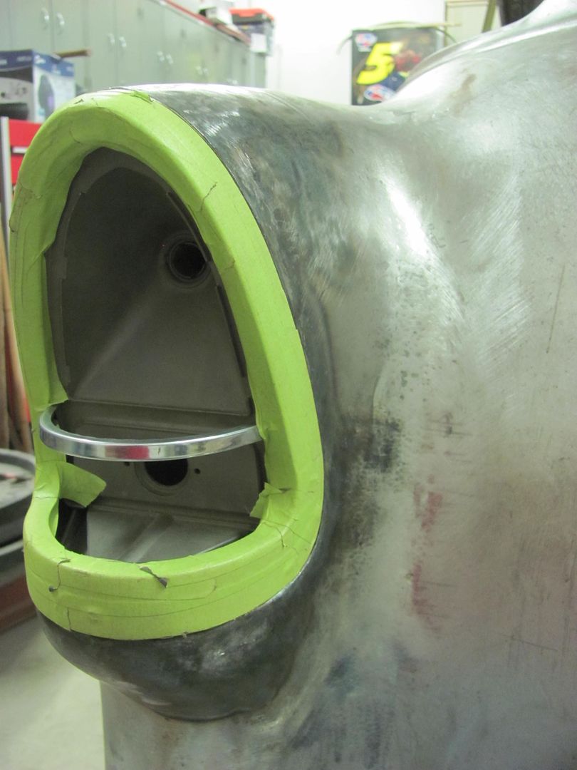
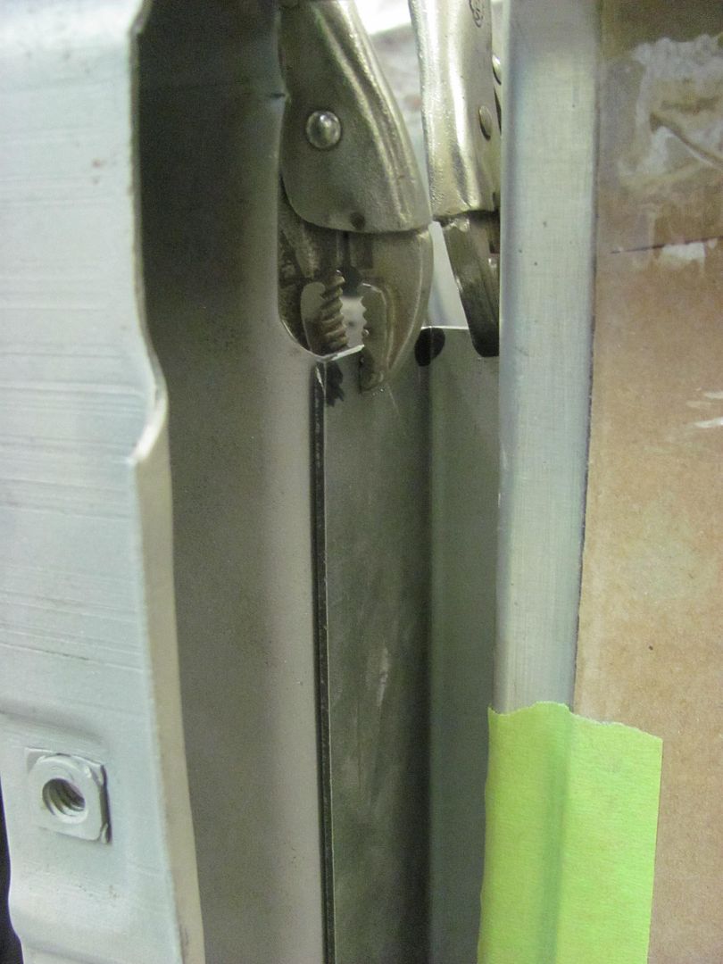
Some trimming of the hole to provide room for the weld-in mounting plate....


Picture%202619.jpg


Picture%202618.jpg


Picture%202623.jpg


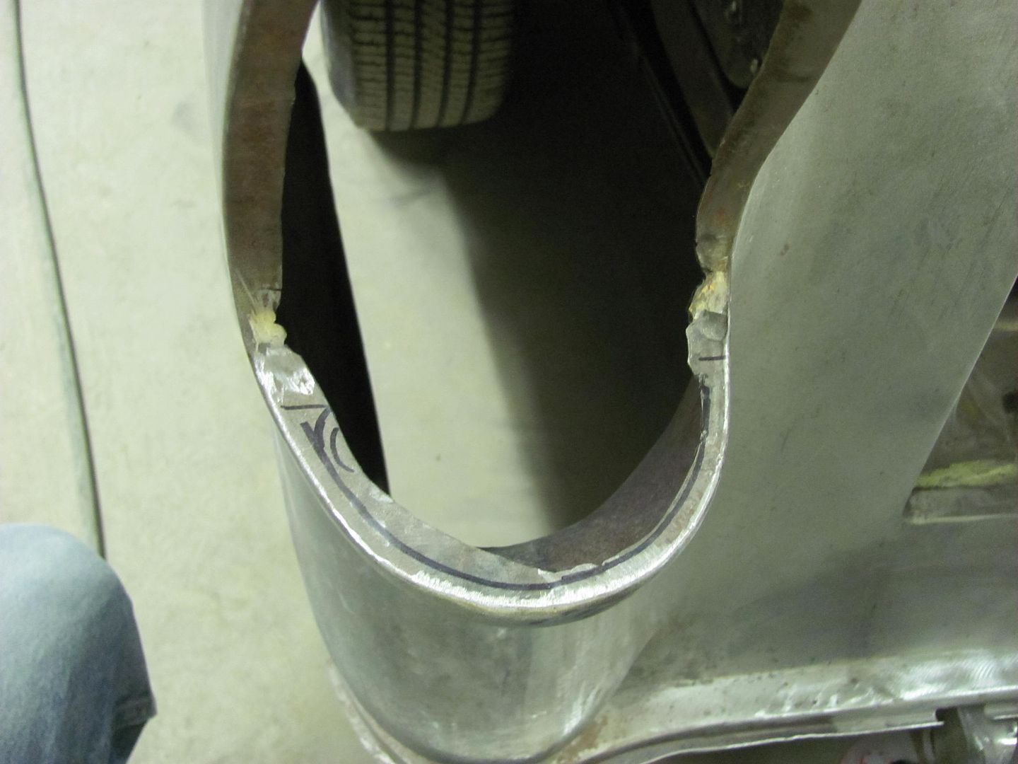
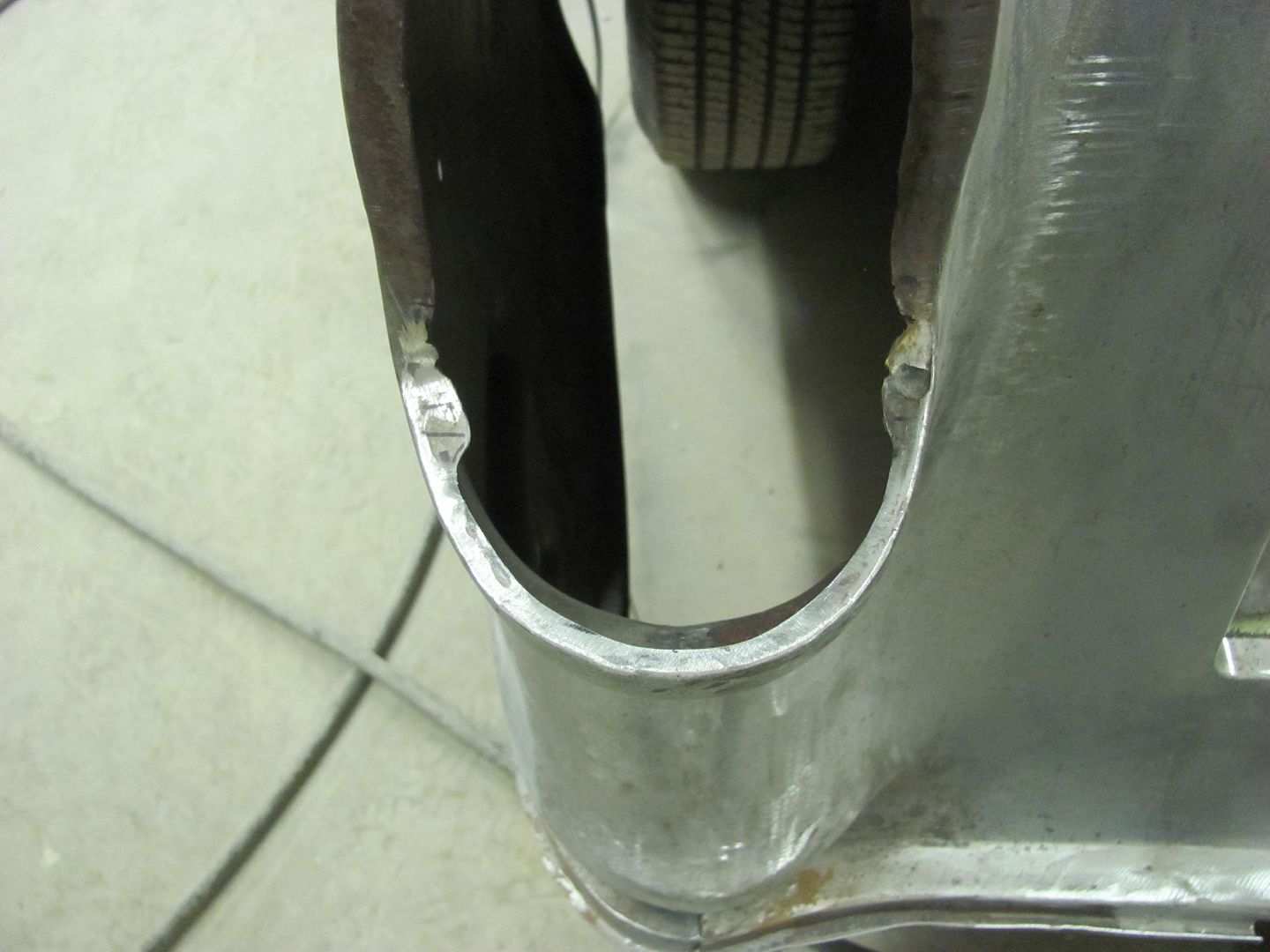
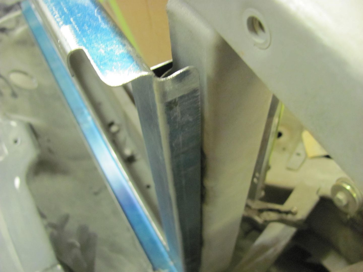
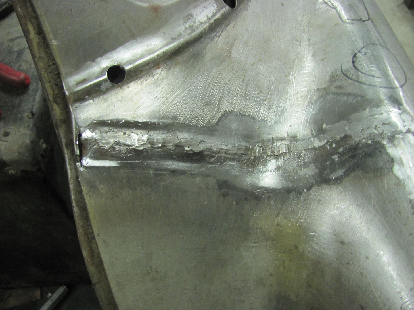
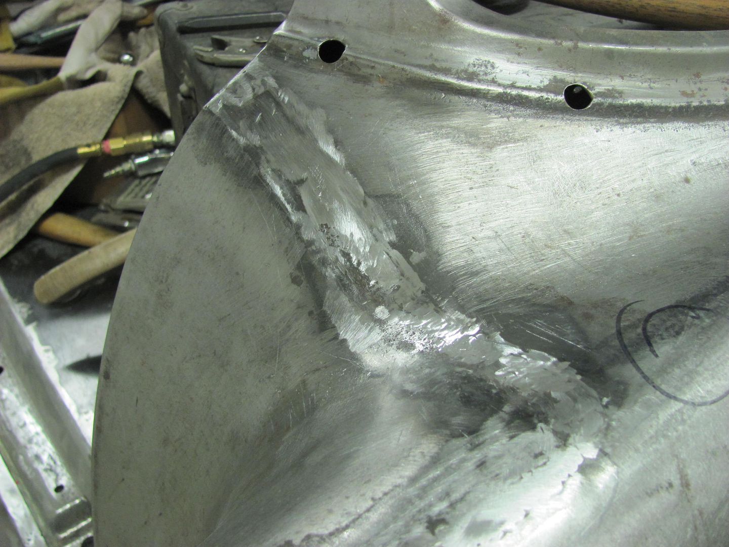
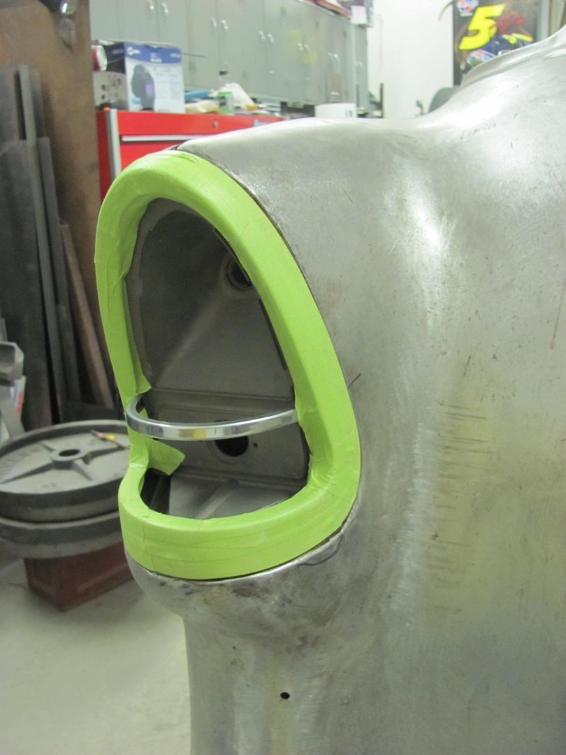
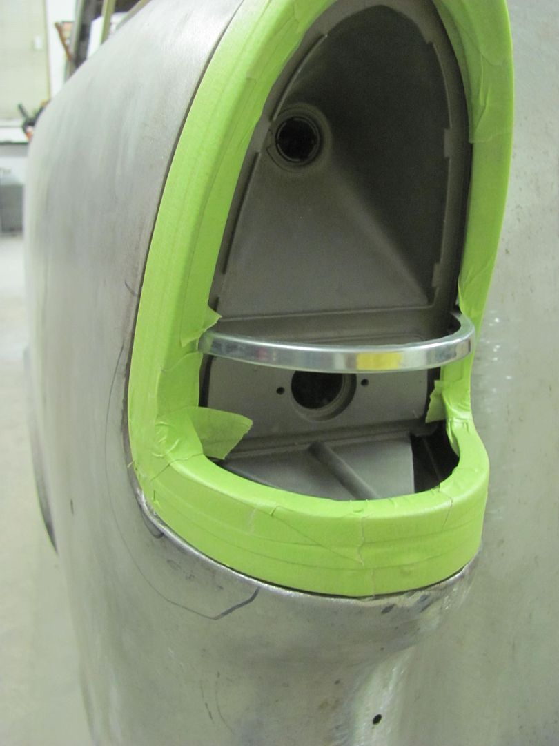
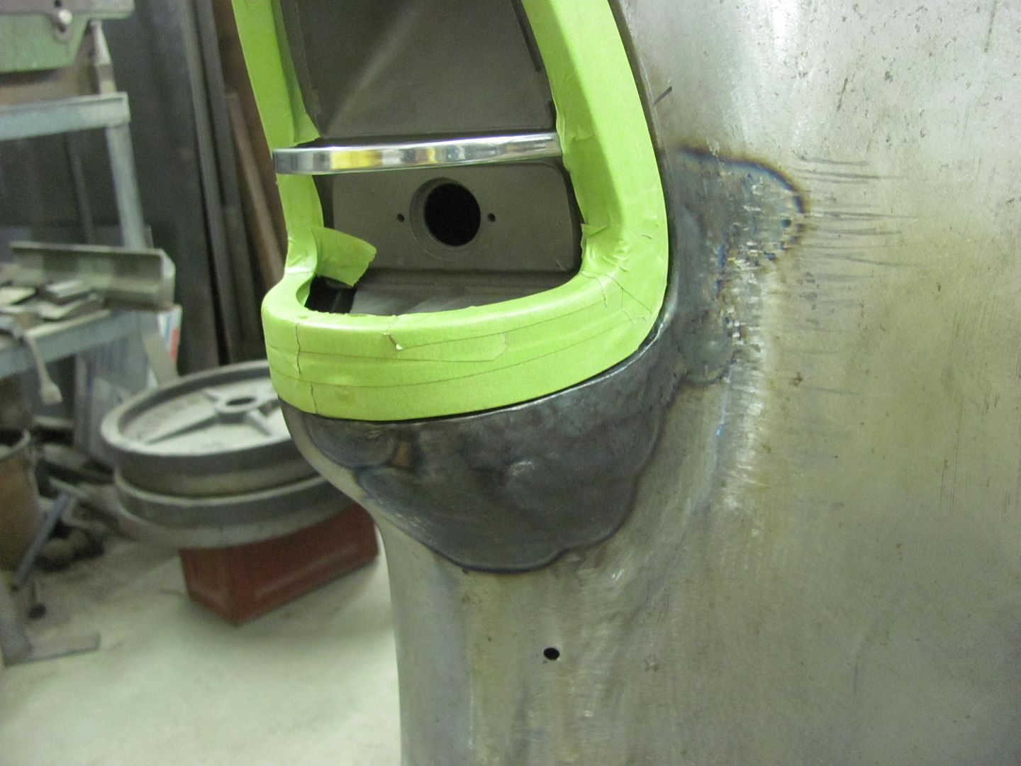
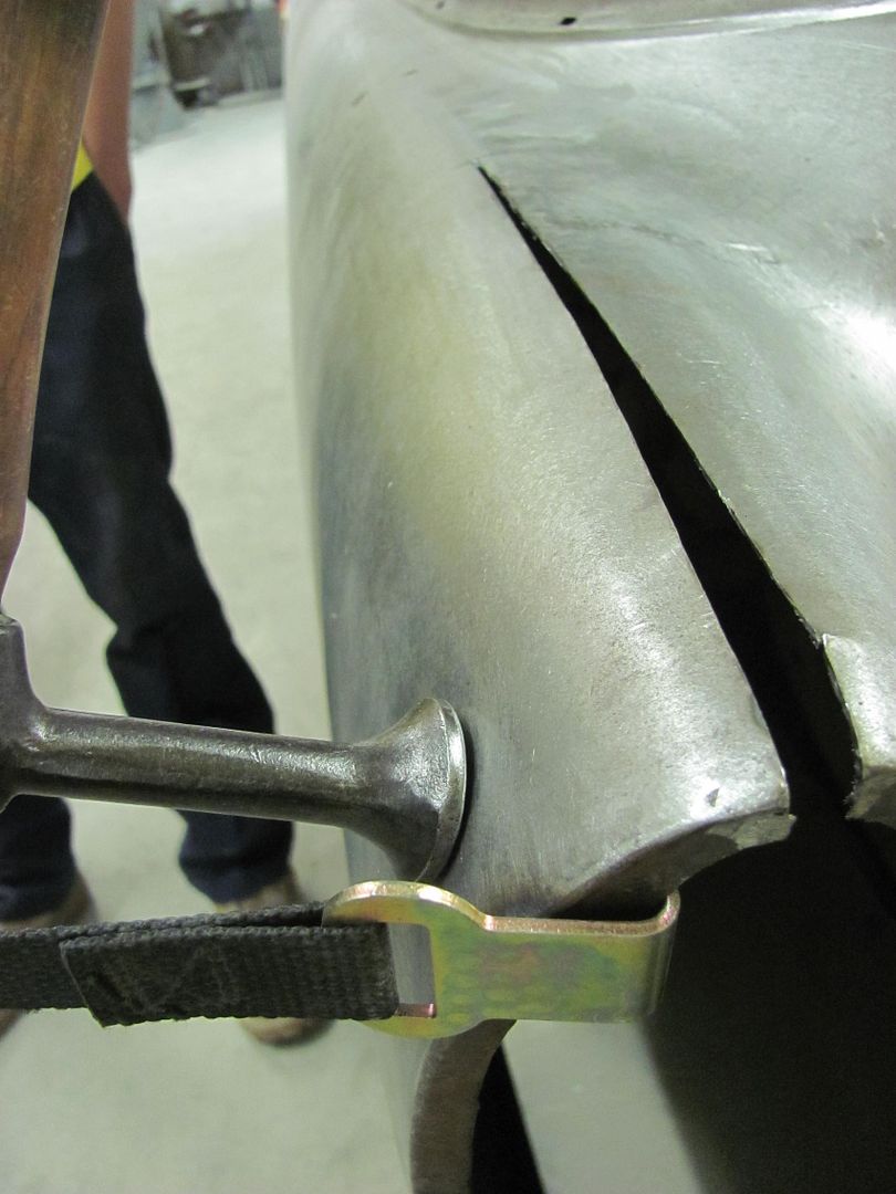
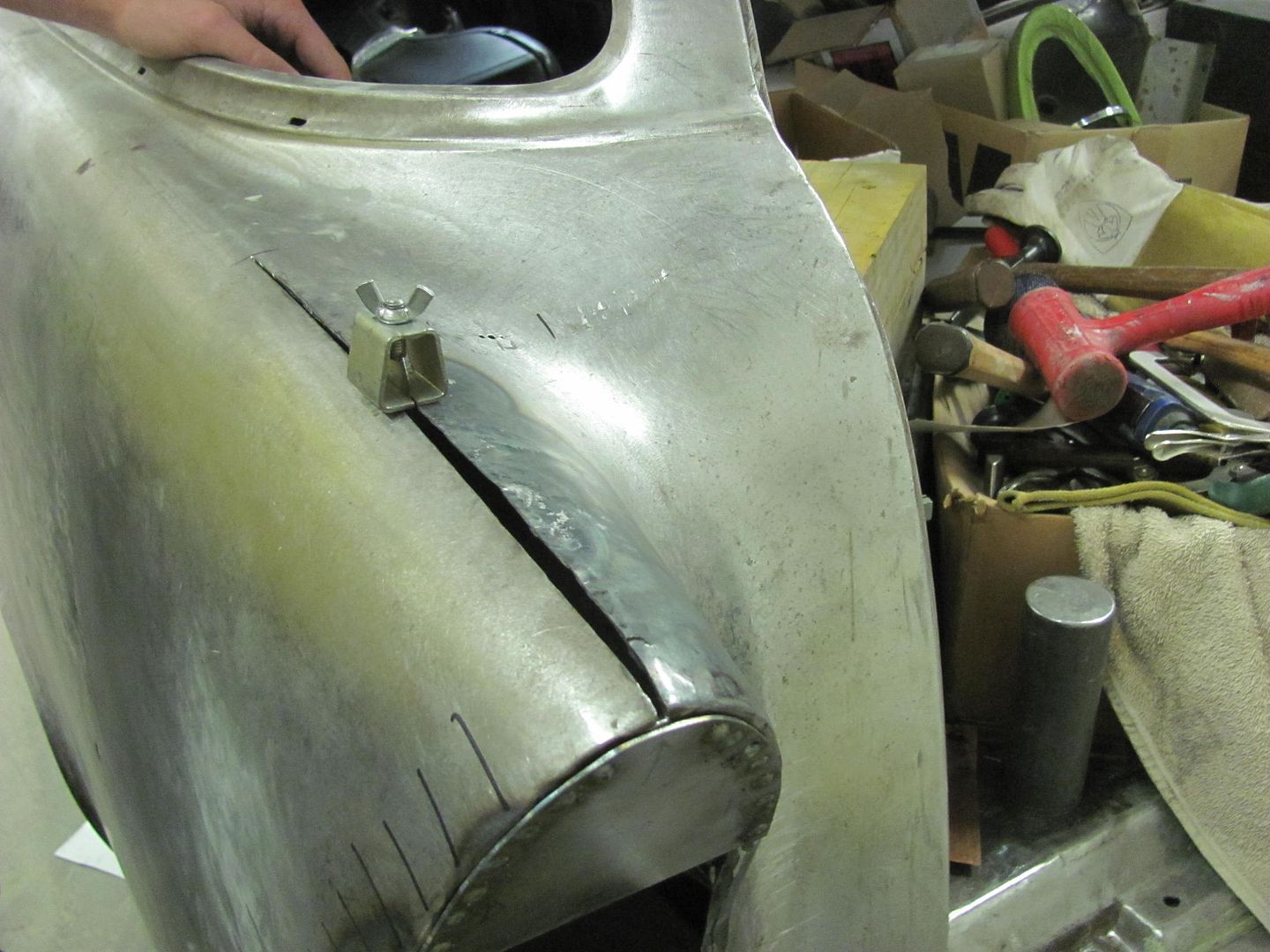
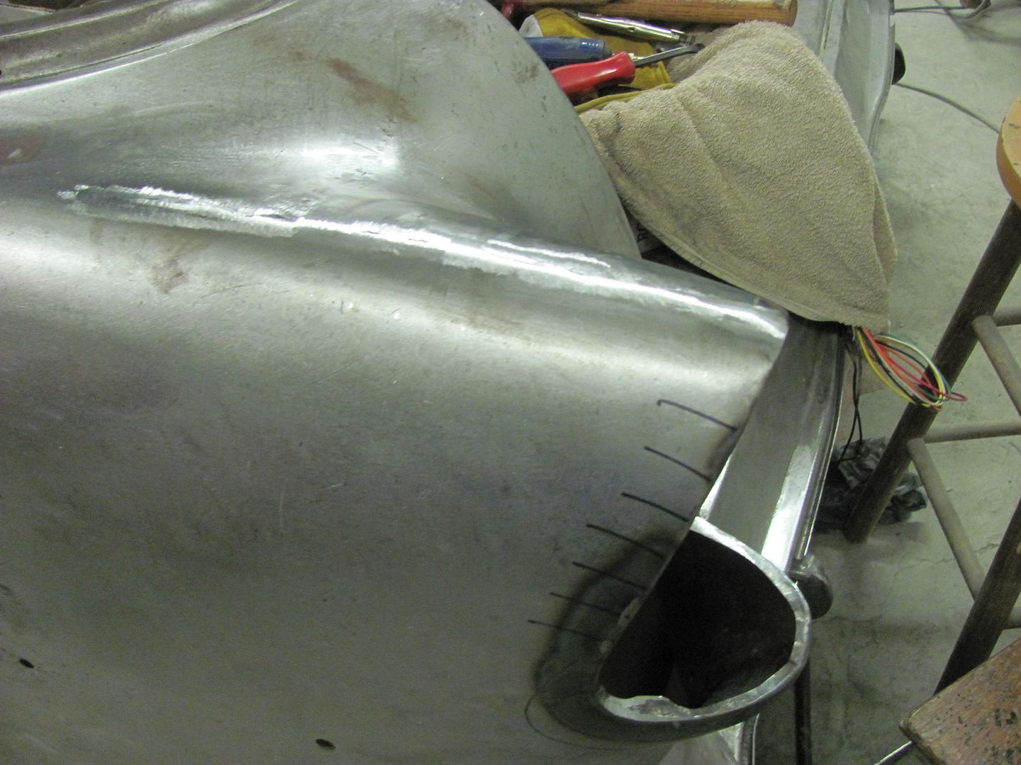
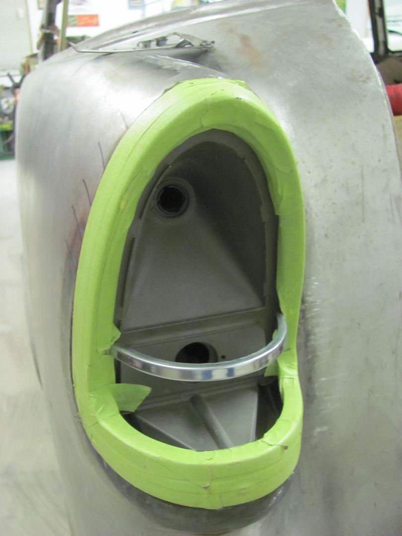
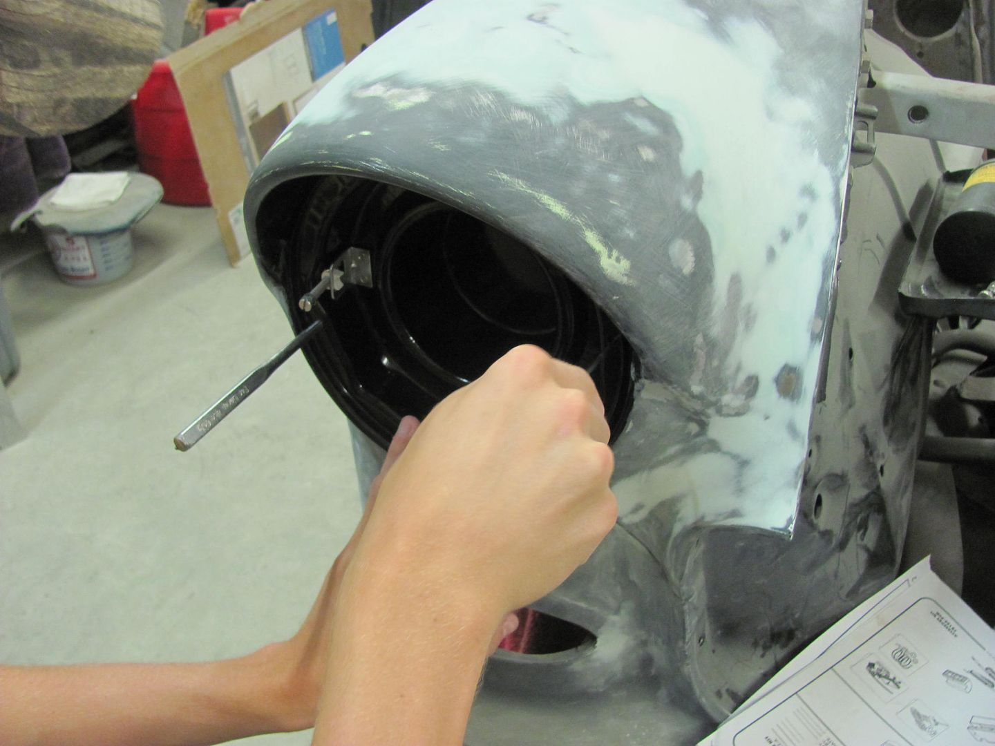
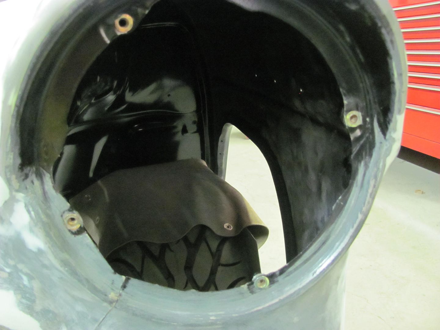
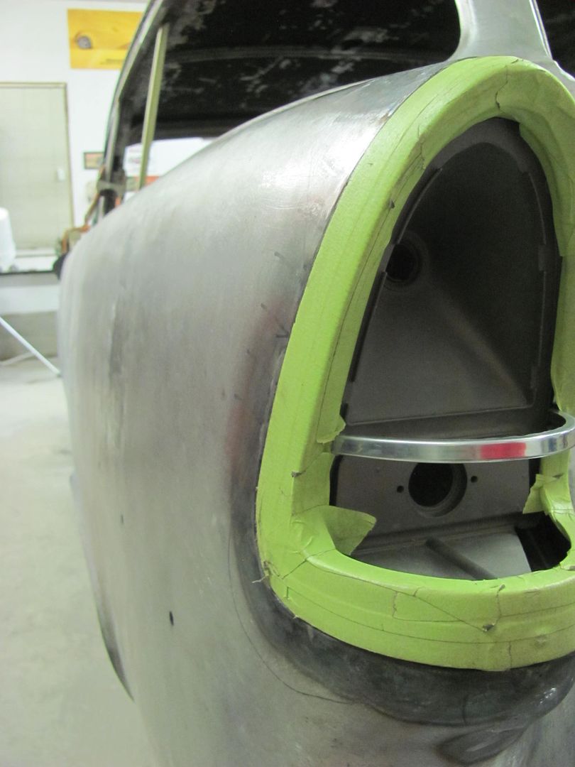
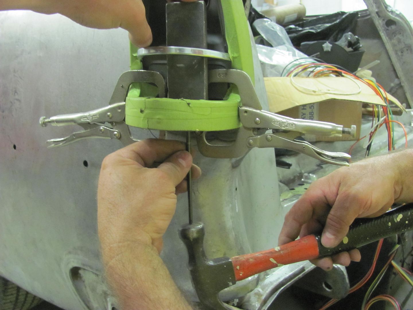
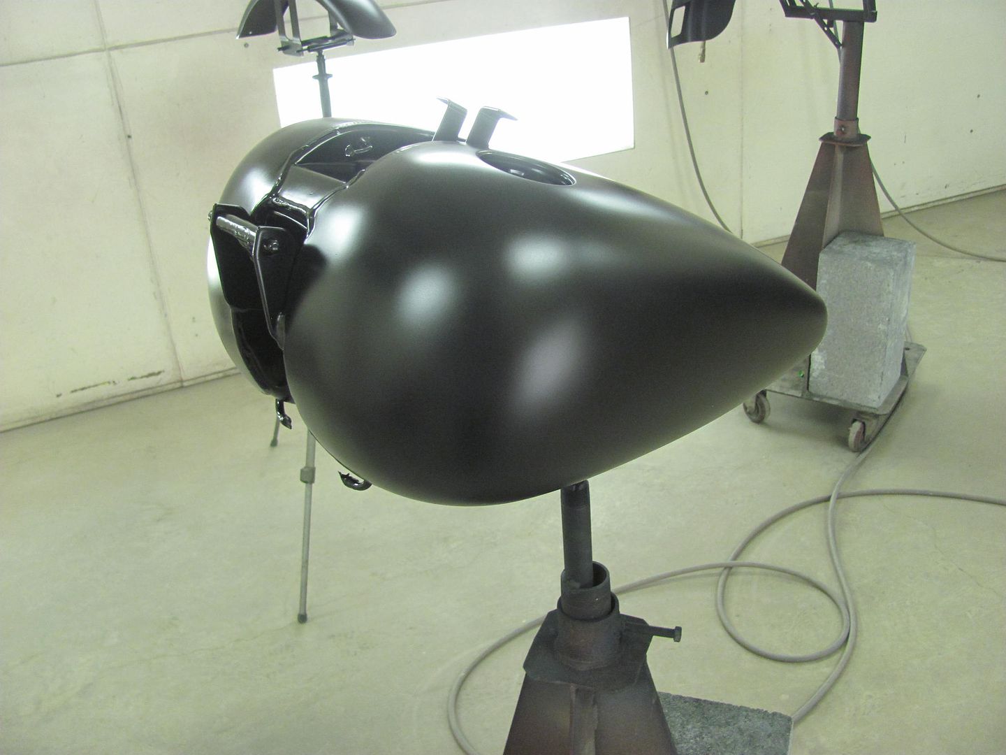
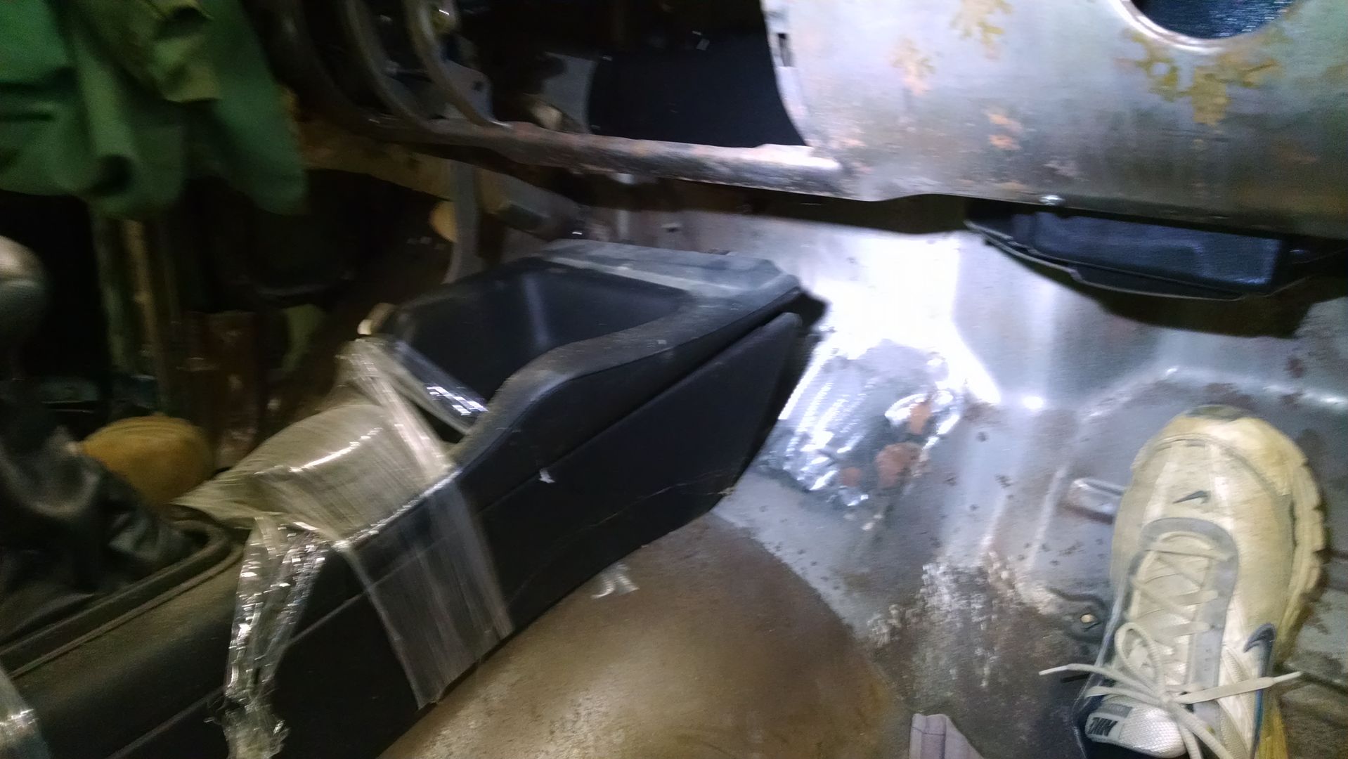
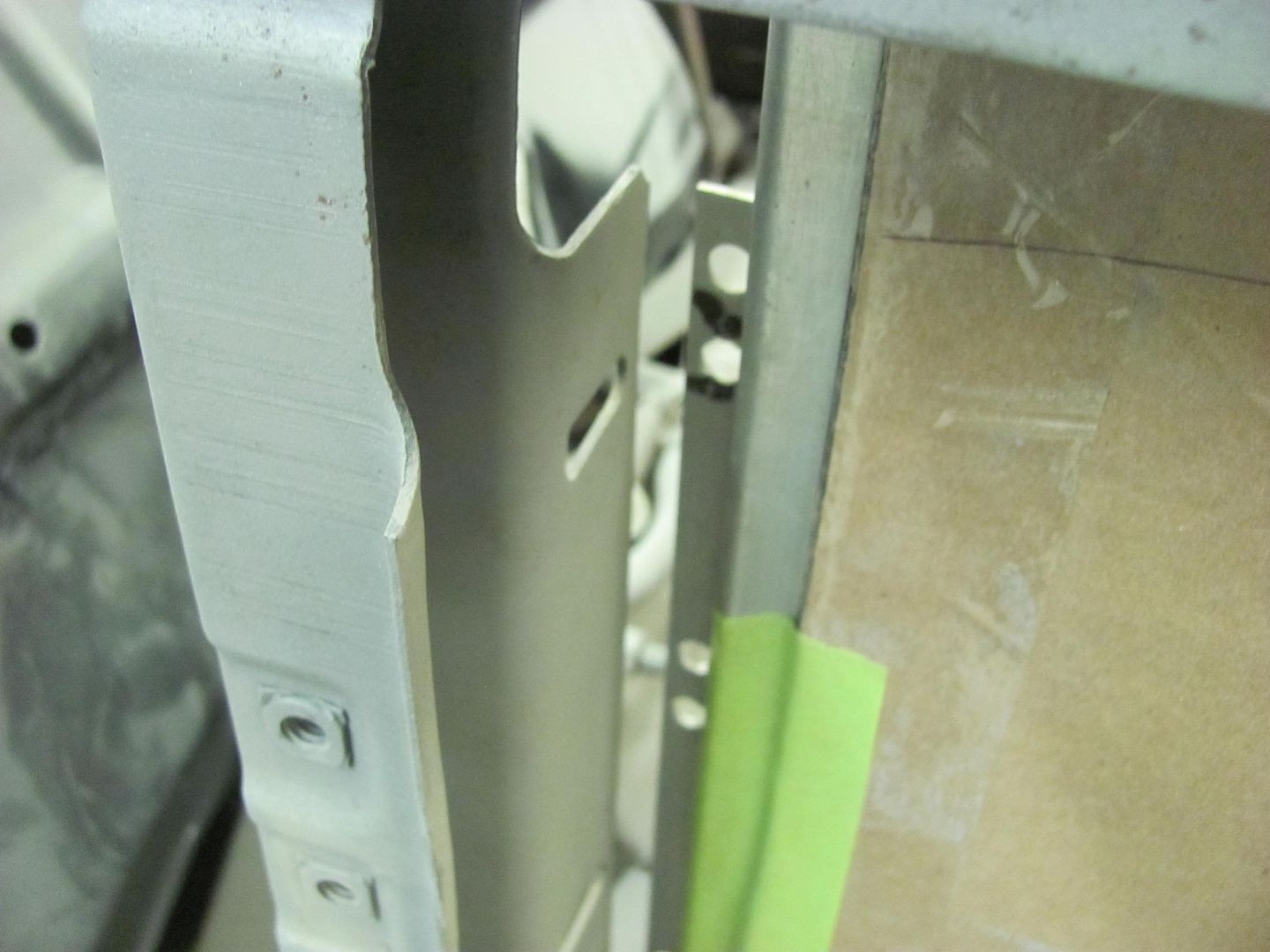
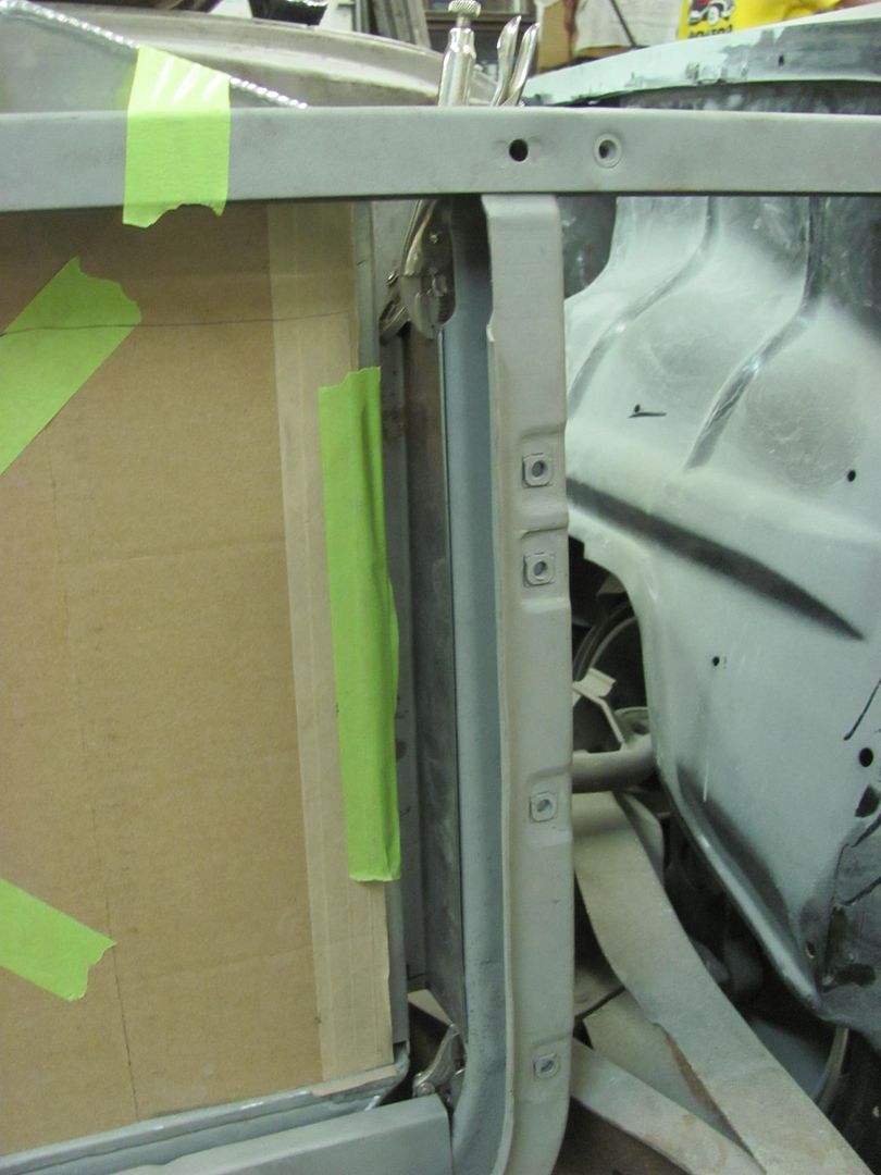
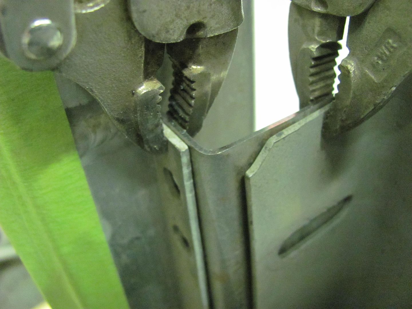
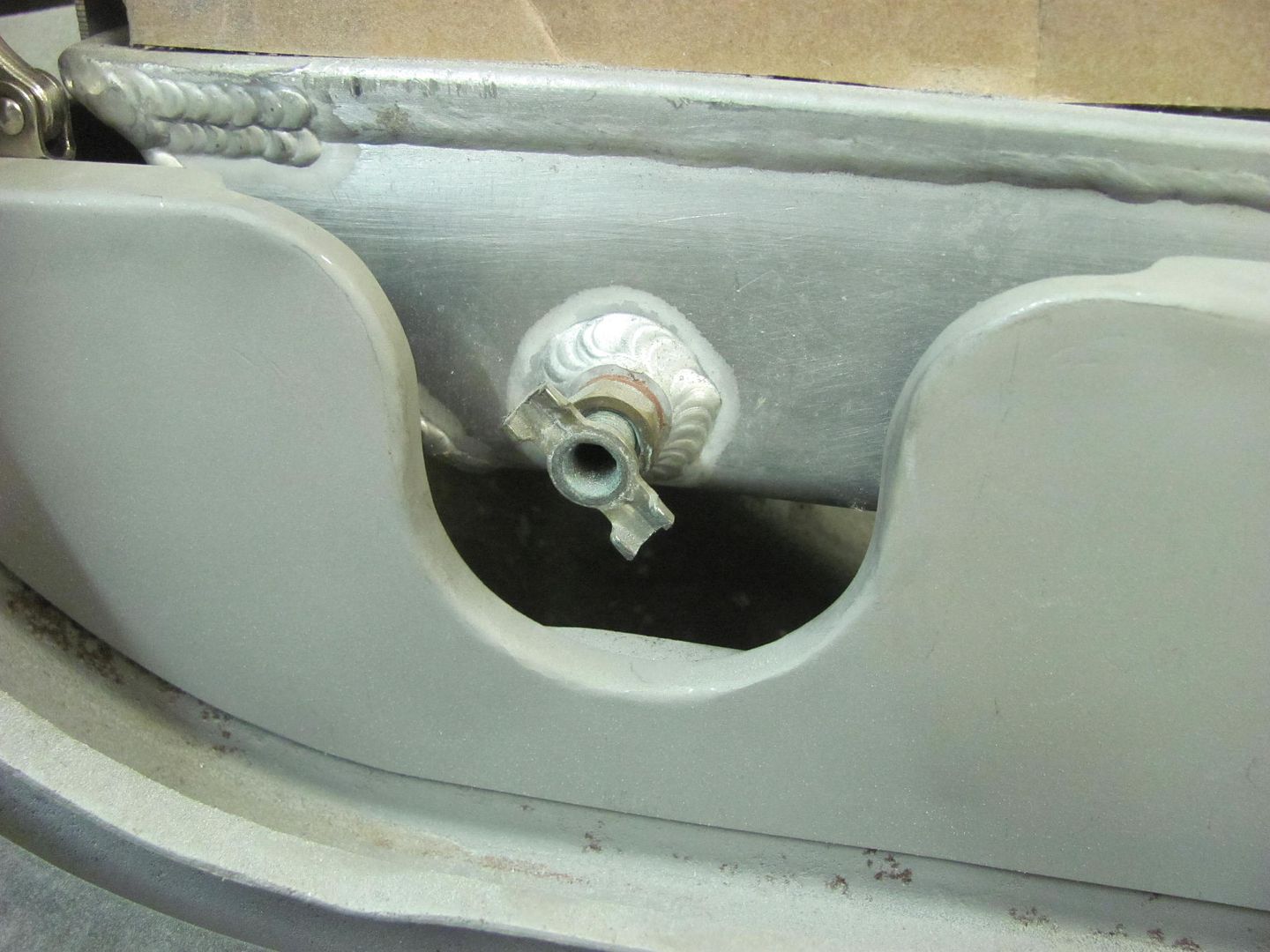
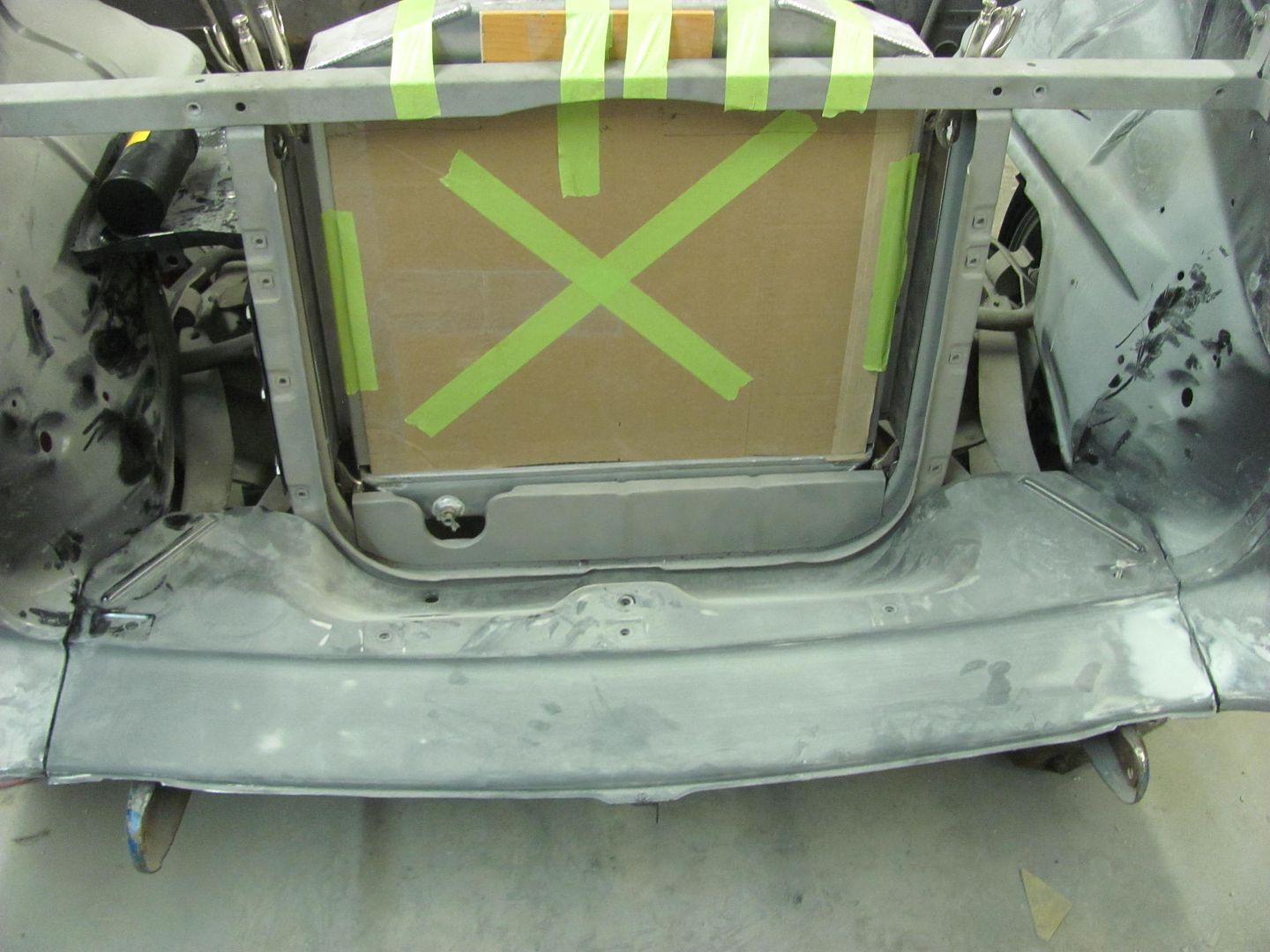
Test fit of the tail light housing showed the opening was a bit wide, especially to the inside towards the tailgate. So some glancing blows with too large a hammer provided a bit of stretch in this inner valley to persuade the panel over to the left, tightening up the opening....


Picture%202624.jpg


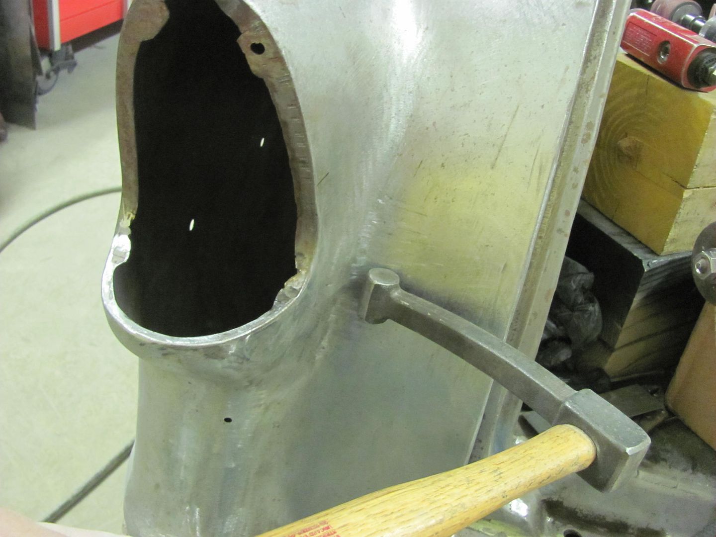
A bit better here, but more tweaking will be needed on the outside before the mounting plate gets welded in place..


Picture%202622.jpg
 
Received a couple of care packages today, first was some of the tailgate hinge trim rings, shown here after Kyle media blasted them. So to all the guys that were watching the ebay auction for these, sorry..


Picture%202630.jpg


Picture%202631.jpg


Next, we got our AC vent samples in.. Here is the test fit with tape... Only have two of the round ones to show, but if we go with these there will be three in a row here in the center of the dash.


Picture%202632.jpg


Picture%202633.jpg


Any thoughts on the vents now with them mocked up?


Then Kyle tried his hand at block sanding epoxy on the inside of the hood..


Picture%202634.jpg
 
Well, the past couple of shop nights we've had some detours and some back up and punts. Where to start..


Started with a test fit of the power antenna the owner had bought, installed somewhat easily and even clears the door hinge when closed by 1/4". But this trim ring on top is just......obnoxious. Anyone use a power antenna that is a bit easier to hide?


Picture%202700.jpg


Next, lets get the VA unit under the dash to see how much room we have to work with on a radio..


Picture%202701.jpg


Picture%202702.jpg


Doh! We had planned on a single DIN chassis, so it appears the radio will need to be 4" deep, or go back into the dash, or go in a console. She did buy a console with the bucket seats, they all came out of a late model Monte Carlo. Let's give that a go.


Picture%202703.jpg


Not much room for installing a single DIN chassis, but even worse the console tapers in at the bottom where the trans tunnel is spreading outward. So it looks like its teeter tottering. Doesn't match the car at all. So this looks like something else to add to the list, perhaps a custom made console is in order..

Since we're not doing too well inside the car, let's shift gears and move to the outside. We had a couple more parts to add to the pile awaiting powder coat. The side baffles of the core support had some hole alignment issues, must be off a 57 or something.... so we'll fill those in and get them re-drilled correctly. Next, we need mounting brackets for the radiator. These were made from some 16 gauge cold rolled steel..


Picture%202658.jpg


Picture%202659.jpg


Picture%202675.jpg


Picture%202676.jpg


Picture%202677.jpg


We do now have much better clearance around the radiator petcock with the new improved version of the lower baffle..


Picture%202678.jpg


Picture%202679.jpg


Kyle had learned some Tig welding this past weekend at GatorMeet, from Gator's boy Dakota. Dakota is quite accomplished for his youth, having won the state competition for welding. Here Kyle runs a couple of practice samples to get the machine dialed in... Seems he forgot his long sleeve welding shirt this evening. :)


Picture%202684.jpg


Picture%202685.jpg


Picture%202686.jpg


I had shown him how to tack without using filler, and gave him more aspiration by showing him a no-filler fusion weld. All in due time..


Practice aside, here is the hole filling effort in the baffle panels...


Picture%202688.jpg


While Kyle worked on filling the holes, I had directed attention to the condenser and the holes we would need to add to the passenger side baffle prior to powder coat... just as shown in the book..


Picture%202662.jpg


....only Murphy had other plans, it appears our condenser was intended for a cross flow radiator...


Picture%202668.jpg


Picture%202665.jpg


Picture%202667.jpg


Hmm..... don't think this is going to work. So to back up and punt, the plan is to make a mounting bracket that will hold this universal condenser to a top flow radiator all while hiding those ugly holes that scream "I'm a universal fit". Then we'll have to get some new hard lines made up that fit correctly.


Picture%202664.jpg


Layout of the mounting bracket...


Picture%202687.jpg


Don't try this at home, it was done on a closed test track...


Picture%202690.jpg


Picture%202692.jpg


Picture%202694.jpg


The ears inside will be folded inward to use the same bolts on the side of the radiator.. Here we are making the top and bottom folds in the magnetic brake, this design will help to hide all those holes..


Picture%202695.jpg


Picture%202697.jpg


Picture%202699.jpg


....and we'll finish the mounting flanges next time..
 
More progress on the condenser mount... The flange fold marks are run through the tipping wheel to better show the bend location. I've found that when using the press brakes this helps to "feel" when the upper die is located properly, less guesswork with the eyeballs where it's harder to see in the press brake dies..


Picture%202712.jpg


Picture%202713.jpg


Clamped in place for a test fit..


Picture%202714.jpg


The side folds add some stiffening as well as hide the bolt heads for the core support baffle plates.


Picture%202715.jpg


Test fit of the condenser...


Picture%202718.jpg


Picture%202719.jpg


Picture%202720.jpg


Picture%202722.jpg


Picture%202723.jpg


Radiator brackets got a nut welded in the bottom hole, the condenser mount will get nuts welded in place for the top 2 sets of holes, so everything will bolt in from the outside in..


Picture%202724.jpg


Picture%202726.jpg


Making the slots for the radiator brackets, used a cone shaped burr....


Picture%202728.jpg


Found that this cutter had less chatter when the cutting edge was perpendicular to the hole opening...


Picture%202729.jpg


Picture%202730.jpg


Picture%202731.jpg


Picture%202727.jpg
 
More progress on the condenser, used some machine screws to attach to the bracket, and some AVK style rivet-nuts in the frame of the condenser to act as a captive nut.


Picture%202747.jpg


Picture%202749.jpg


Bolted in place...


Picture%202752.jpg


Picture%202753.jpg


Meanwhile Kyle ties up some loose ends, finishing the weld across the remaining "shaved" lead seam on the passenger quarter.. It does need some grinding on the underside of the weld still but we'll wait for the car to be on the rotisserie for easier access.


Picture%202765.jpg


Picture%202766.jpg


Picture%202770.jpg


Picture%202771.jpg


Fitment of the Driver's side tail light... this was even worse than the passenger side in fitment, and we did need to make a relief cut at the top, but after some massaging, it's getting close. A few more tweaks to get this done and then the headache of installing the motorized tail light pivot for fuel fill access..


Picture%202768.jpg


Picture%202769.jpg
 
Sorry for the slight hiatus, been in UK and just got back this past weekend. Time to catch up on what we had done before I left and what Kyle did while I was gone to take up my slack..


Part of our fitment issue with the passenger tail light was that we are installing the "hidden fuel fill" which required the removal of the brace welded in the opening. Next, when the old quarter was cut off and the new one installed, without the brace in place both pieces tended to wrap to the right, which can sort of be seen in the following picture, where its flush above the inside corner and rotates to the right upwards of that. The outer quarter was rotated in a similar fashion. We weren't having much luck in resolving the issue with the top weld seam remaining, so a relief cut was added, a restraint device employed to make use of some off dolly bumping to eliminate some of the right rotation. I didn't get a good picture of it, but you can see where the inner quarter comes in considerably upwards of the tail light right corner..


Picture%202772.jpg


Anchor


Picture%202778.jpg


Off-dolly bumping...


Picture%202779.jpg


Then some shrinking was used to pull in the inner quarter, and a 16 ga plate used to hold things in place while the top seam was re-welded.


Picture%202780.jpg


Picture%202782.jpg


Kyle got the seam welded closed...


Picture%202789.jpg


And temporary brace removed...


Picture%202791.jpg


Much better, almost ready to tackle the "fuel door" pivot...


Picture%202793.jpg
 
Got another care package in the mail... The new escutcheon for the antenna looks like it will work, the hole size matches the nut on the antenna and we'll just need to get rid of the flat spot/keyway in the hole. Only I don't think we'll be using this one. Between a recess under the chrome and visible scratches in it, this one's going back.


Picture%202817.jpg


Picture%202818.jpg


Picture%202819.jpg


On to the next new pieces, hopefully these fit better, Reproduction headlight buckets..... wanted to test fit all the headlight and turn signal pieces before re-priming the fenders..


Picture%202801.jpg


Decided to use some AVK rivet nuts over the u-clips..


Picture%202801.jpg


Picture%202802.jpg


Picture%202804.jpg


Picture%202805.jpg


Picture%202816.jpg


Parts fitted..


Picture%202812.jpg


Picture%202814.jpg
 
Well this isn't much of an update, but since Kyle was busy media blasting some parts I had torch and hammer duty.. So to have a place to drop the torch quickly, bent this up:


Picture%202820.jpg


Picture%202821.jpg


When the top seam was welded we had a slight bulge just in from the tail light. So some dime sized spots were heated and then hammered with glancing blows to bring things down a bit.. The fit of the tail light is much better now, and we've started the fitup of the motor assembly's mounting plate. Should get that welded in tomorrow..


Picture%202822.jpg


Picture%202823.jpg
 
i remember the first time i saw that torch set . a guy was welding beer cans together at a show. was also cutting some 3/4 in steel. amazing tool .
bought one and still cant weld beer cans...... but i can make them available :)
 
HaHa, I hear that.. This one is a Henrob, one of the many names this torch has gone through as the company changed hands.
 
Worked on the Rocky Hinge hidden fuel door this evening. The mounting plate we made is plug welded to the tail light opening..


Picture%202825.jpg


Slight trimming needed.....


Picture%202827.jpg


Then some 3M body molding adhesive tape is added to the top of the pivot bracket and the lens pressed in place. Here's the initial test...


https://youtu.be/oZ6JYr988dc


That worked fairly well, so it was clamped in place and a transfer punch used to mark the housing for drilling mounting holes..


Picture%202829.jpg


Then the holes were slightly slotted using a dremel for side to side adjustability. Here's the results, from different views....


https://youtu.be/848V2PbuQJw


https://youtu.be/N_Qz0NZxh5g


https://youtu.be/PVeWQyb35j8


OK, now for the bad that we found with the kit... The original lamp housing must be removed for clearance, and a new (included) one gets installed below the original position. The new housing has those spring loaded contacts that some tend to bend over and short out, so I gave the wires a couple gentle tugs to see if the contacts deflected toward the outside shell...


Picture%202834.jpg


Picture%202835.jpg


Surprise, surprise, the contacts pulled clean off....


Picture%202836.jpg


Note there is no copper inside the contacts, indicating these had a loose crimp...


Picture%202837.jpg


Picture%202838.jpg


Next, the operation of the motor function seemed to be intermittent. A recheck of the power connections showed no issues, so we pressed a bit harder on the switches toggle, and the function returned. Multiple repeat attempts were performed and the switch proved to be the culprit. It appears to be a cheapo switch that has intermittent contact function. So looks like we'll be replacing a couple of the parts for this kit... So much for everything you need in one package....


Picture%202833.jpg
 
Neither one of the "junk pieces" had the country of origin, so they must have known it was absolute junk when they were making it.. ;)


Recently I took delivery of a ball glove pounding pad, $39 on Amazon per a link posted by Johnny Arial on AllMetalShaping. It was very light, and where I did not give it a go with a sheet metal test sample, something in me wanted to see what was inside the bag. So here we go, can't leave well enough alone... :p

Picture%202848.jpg


Picture%202850.jpg


Picture%202849.jpg


Looks like a high density felt pad...

Picture%202851.jpg


Picture%202852.jpg


My previous shot bag had become a casualty inside of a quarter panel when using it as a dolly... It found a sharp piece of metal which caused the tear... and I caused the cut so I could empty it out and pull it out of the cavity it was in.. It had approx. 50 lbs or better of lead shot in it at the time, and for some reason I didn't think about removal when I was dropping it in the hole.

Picture%202853.jpg


Picture%202854.jpg


So I had put in an order last night for another bus seat cover (Kevlar material) and took it today with all the pieces to Anthony's Upholstery. This one is a bit smaller, so also more manageable. I think I had about 1/3 of the 50 lbs left over, so may have to make another smaller shot bag..

Comparison, the old to the new one..

Picture%202855.jpg


Picture%202856.jpg


Something told me when that Amazon order was placed that this thing would have lead shot inside before all was said and done.. It does make a nice shot bag, and has a nice look. :D

Picture%202857.jpg


Picture%202859.jpg


Picture%202860.jpg
 
More progress on the wagon, got some SPI epoxy sprayed, hopefully this will wet sand out and be ready for BC/CC.


Picture%202888.jpg


Picture%202889.jpg


Picture%202890.jpg


Picture%202891.jpg


Also got some primer on the sheetmetal for an 01 Dyna


Picture%202892.jpg


Picture%202893.jpg


Picture%202894.jpg


Look Scott, the dent's gone...


Picture%202896.jpg
 
Kyle learning the fine art of blocking....


Picture%202898.jpg


Picture%202903.jpg


Picture%202908.jpg


Meanwhile, I was wet sanding the motorcycle parts...


Picture%202900.jpg


Picture%202904.jpg


Picture%202905.jpg


Picture%202907.jpg


This SPI epoxy sure is nice sanding!
 
Back
Top