You are using an out of date browser. It may not display this or other websites correctly.
You should upgrade or use an alternative browser.
You should upgrade or use an alternative browser.
Wagon Progress
- Thread starter MP&C
- Start date
MJM
Promoted Users
The metal fabrication that has been done, and the metal fabrication that is being done now, just amazes me.
I don't know who the young man is that's assisting you but, I hope he's paying attention. He's getting hands on experience that could last him a life time.
Seriously, thanks for sharing. I know it takes time to make these threads and posts. Many here greatly enjoy them, including myself.
I don't know who the young man is that's assisting you but, I hope he's paying attention. He's getting hands on experience that could last him a life time.
Seriously, thanks for sharing. I know it takes time to make these threads and posts. Many here greatly enjoy them, including myself.
MP&C
Member
Thanks guys!
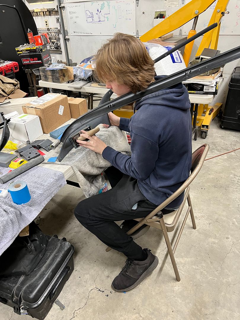
I have two guys helping out, one is a Jet mechanic and the other just graduated high school with plans on a Mechanical Engineering degree.
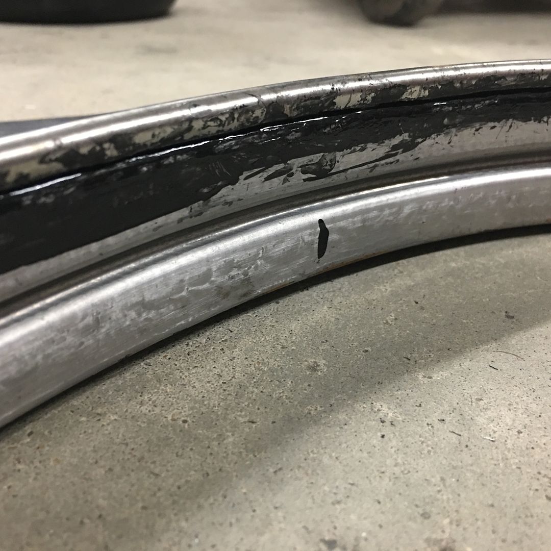
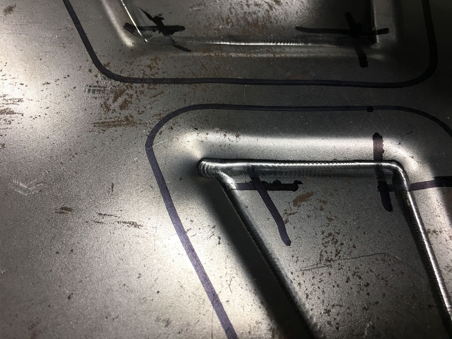
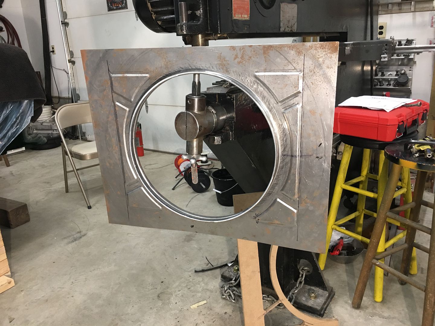
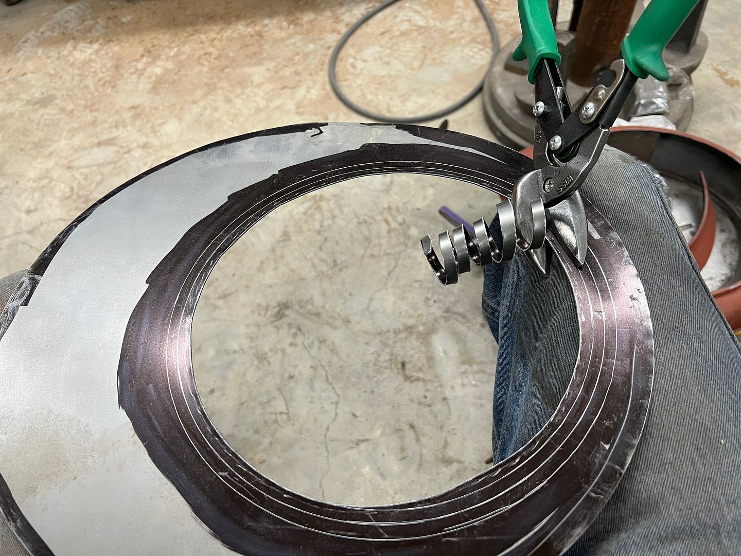
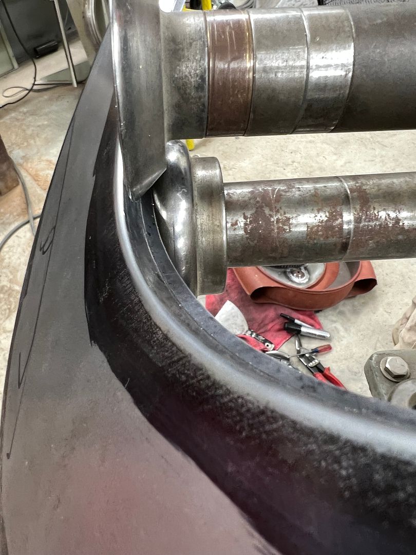
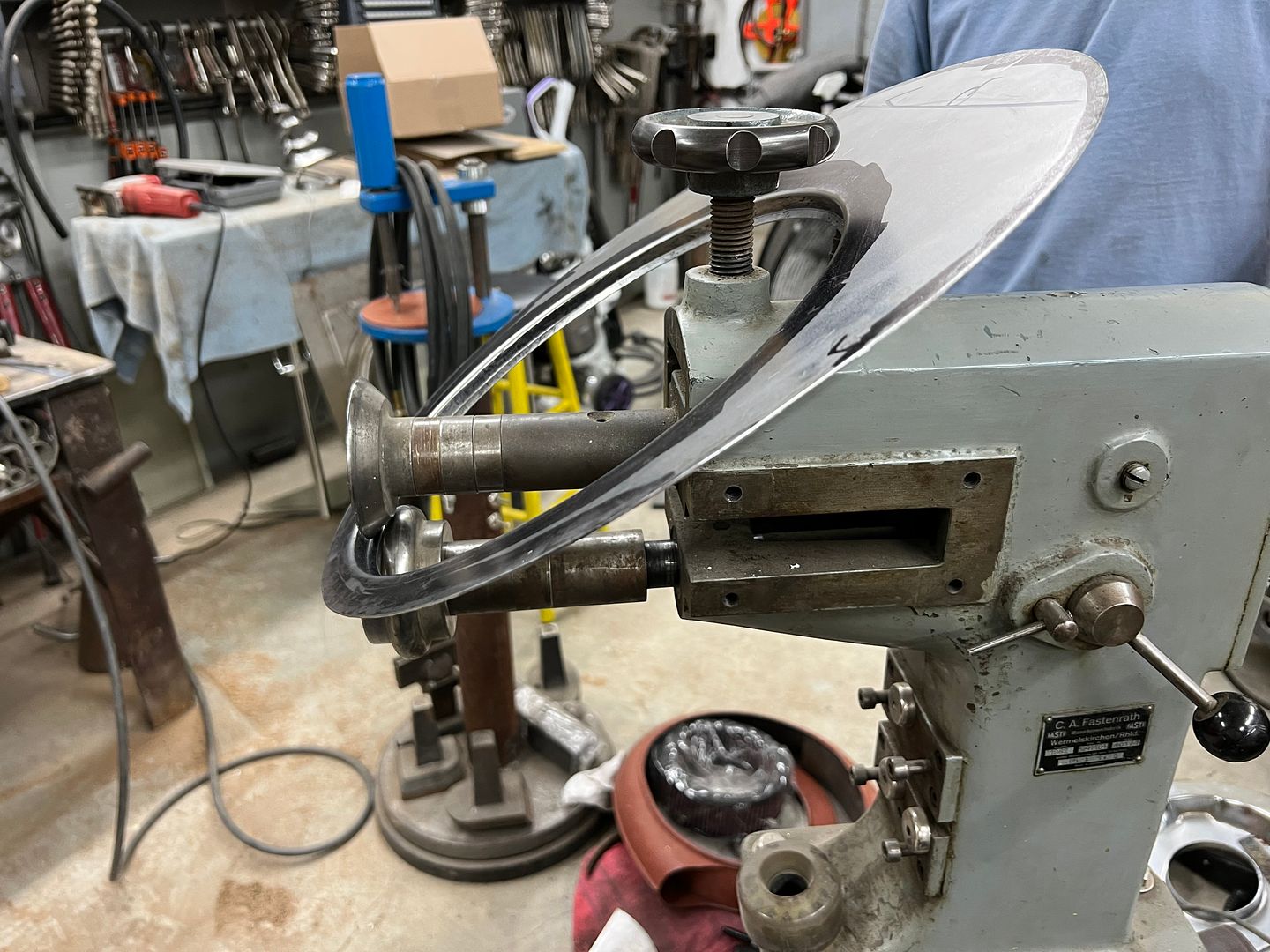
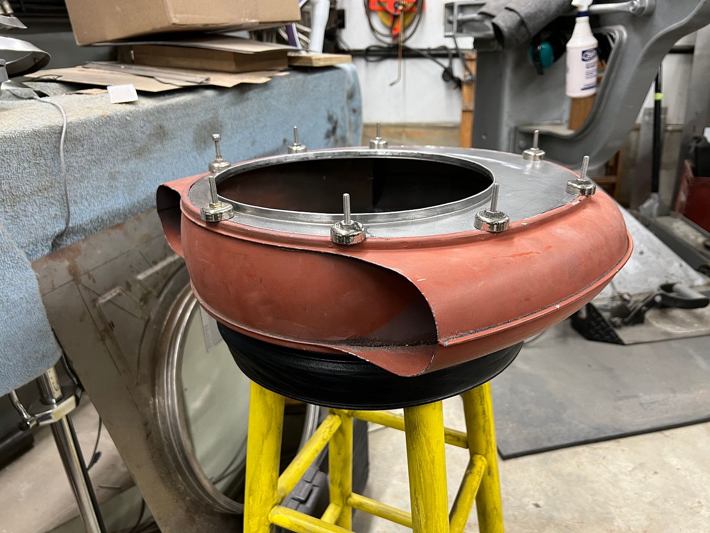
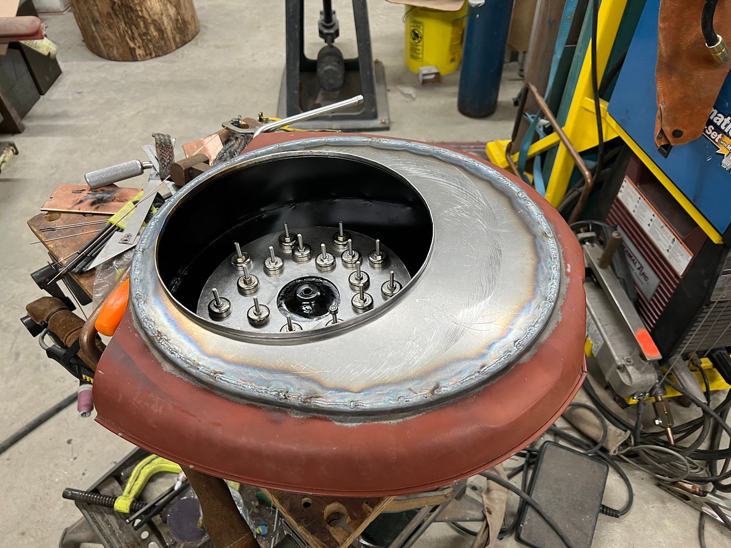
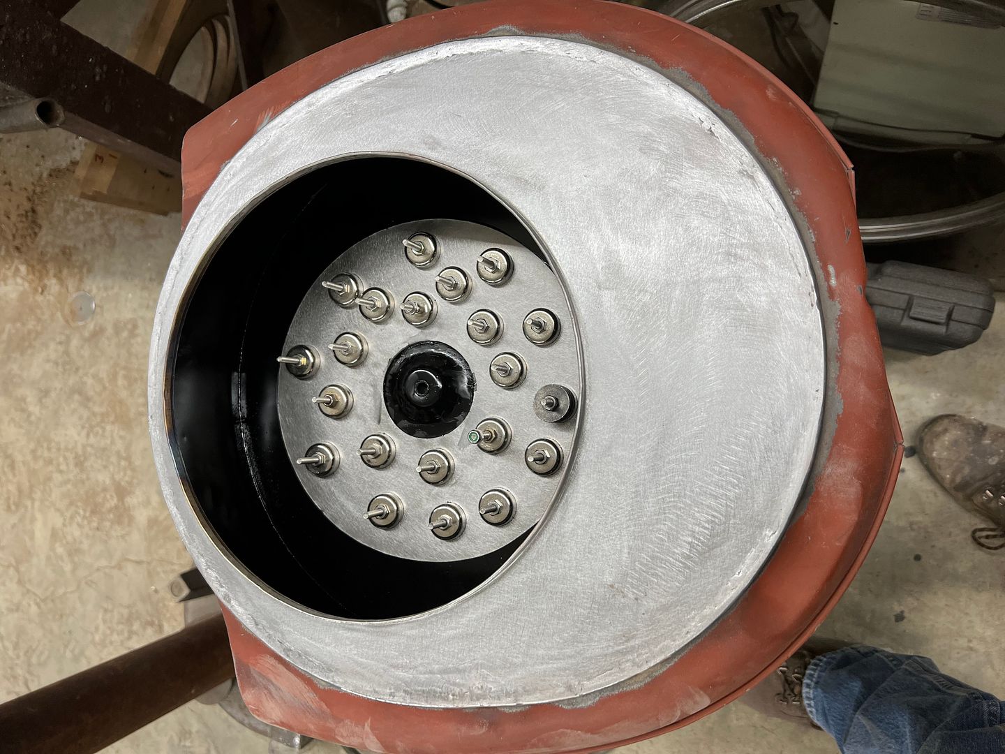
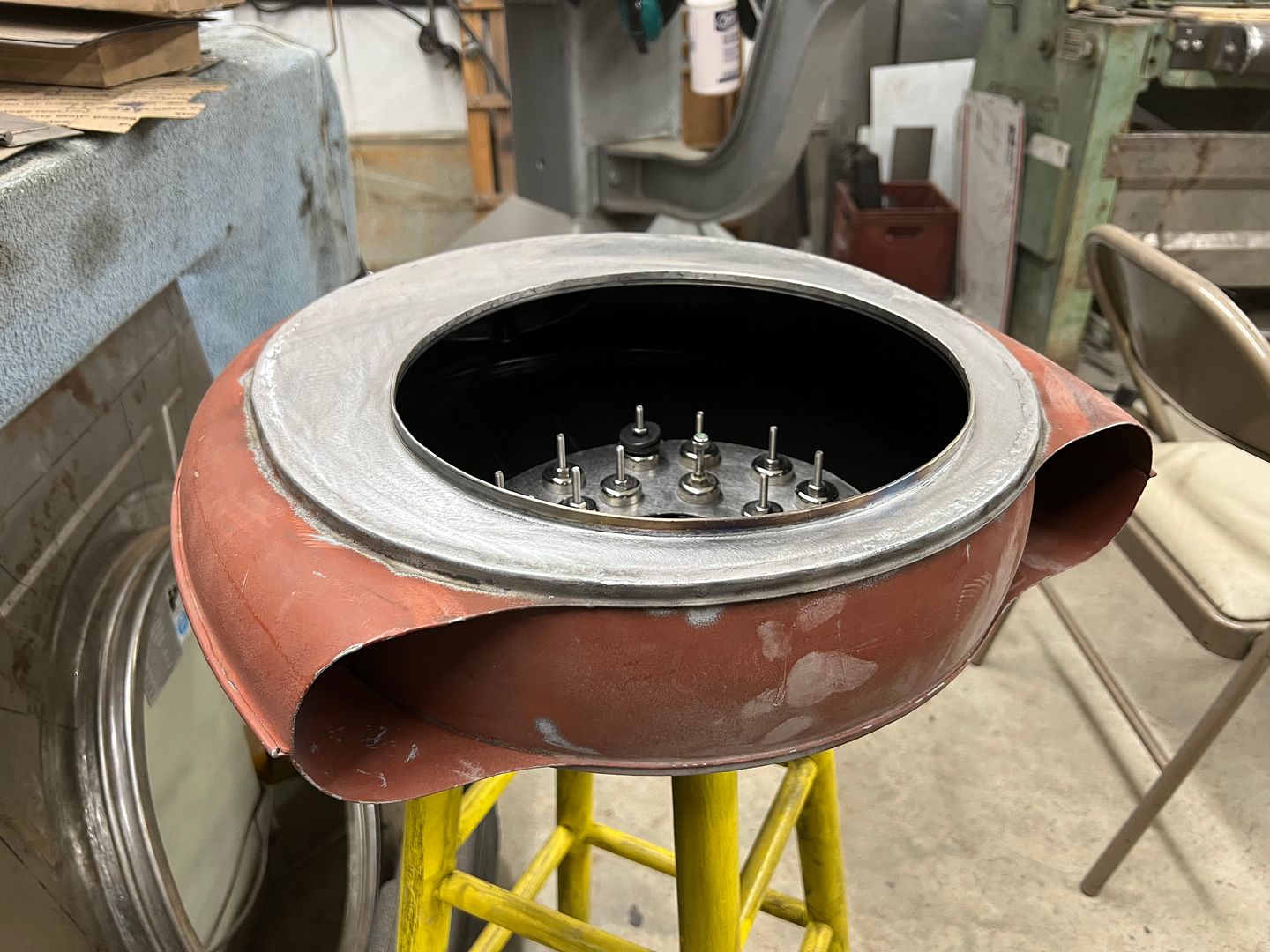
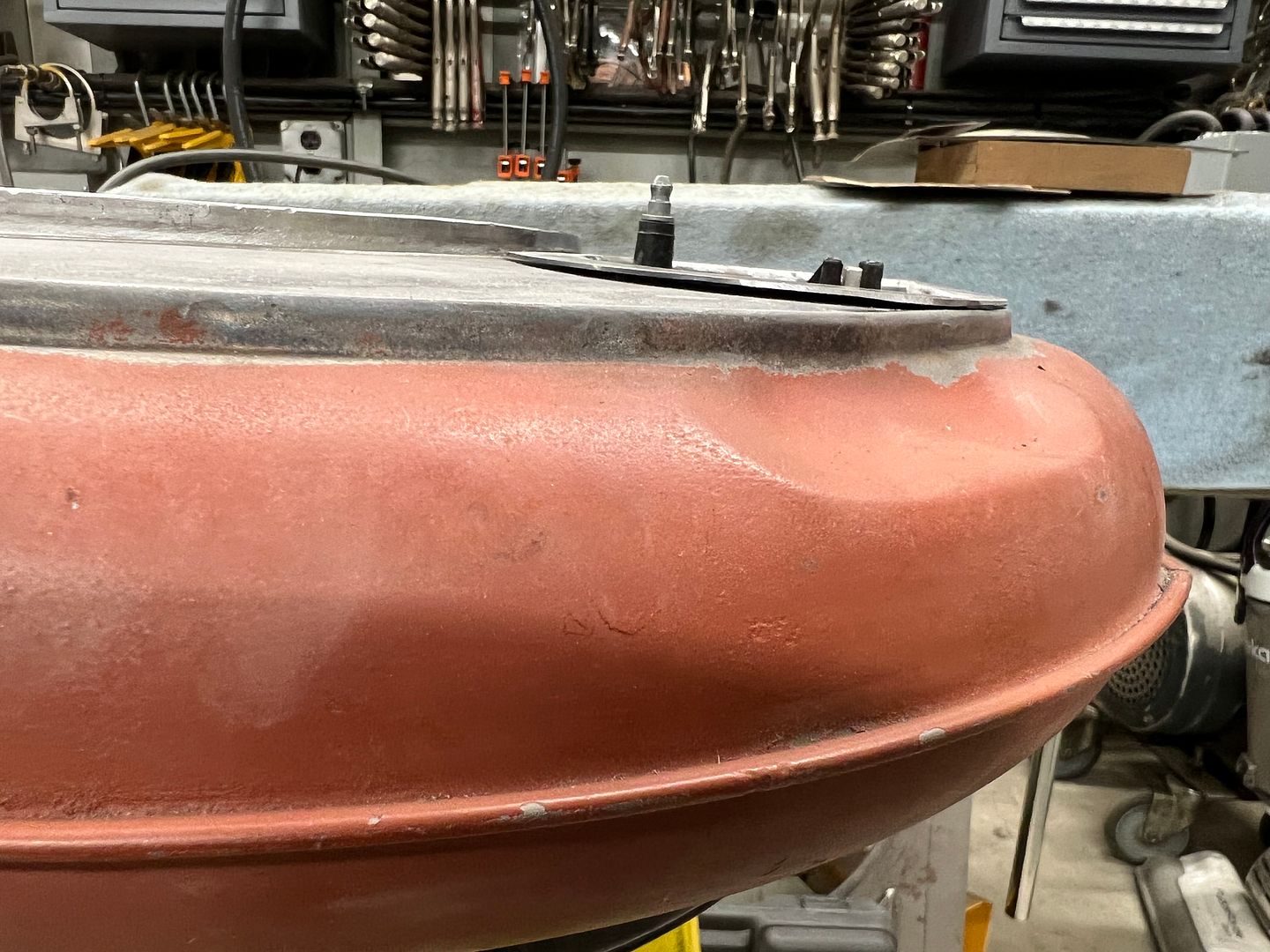
More progress on the fan shroud... Wire edging!! In order to stave off any rust issue as long as we can, I normally treat the wire channel to epoxy primer from the inside-out. So we used a scotchbrite pad and some Ivory liquid in warm water to remove any last remnants of the WD40 used for the last shaping effort on the Lennox.
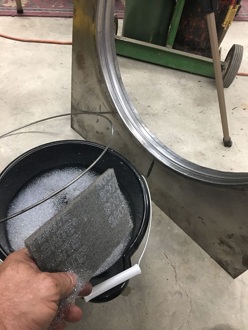
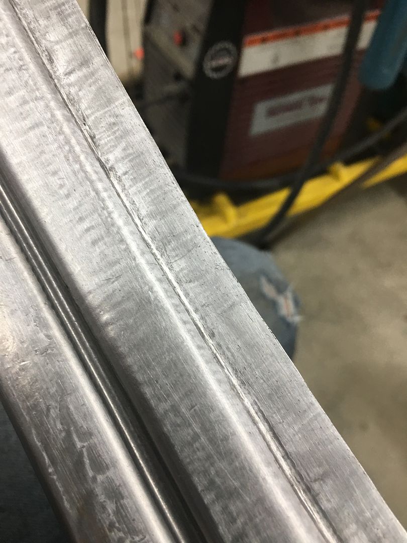
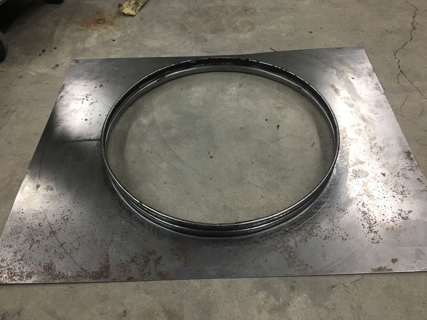
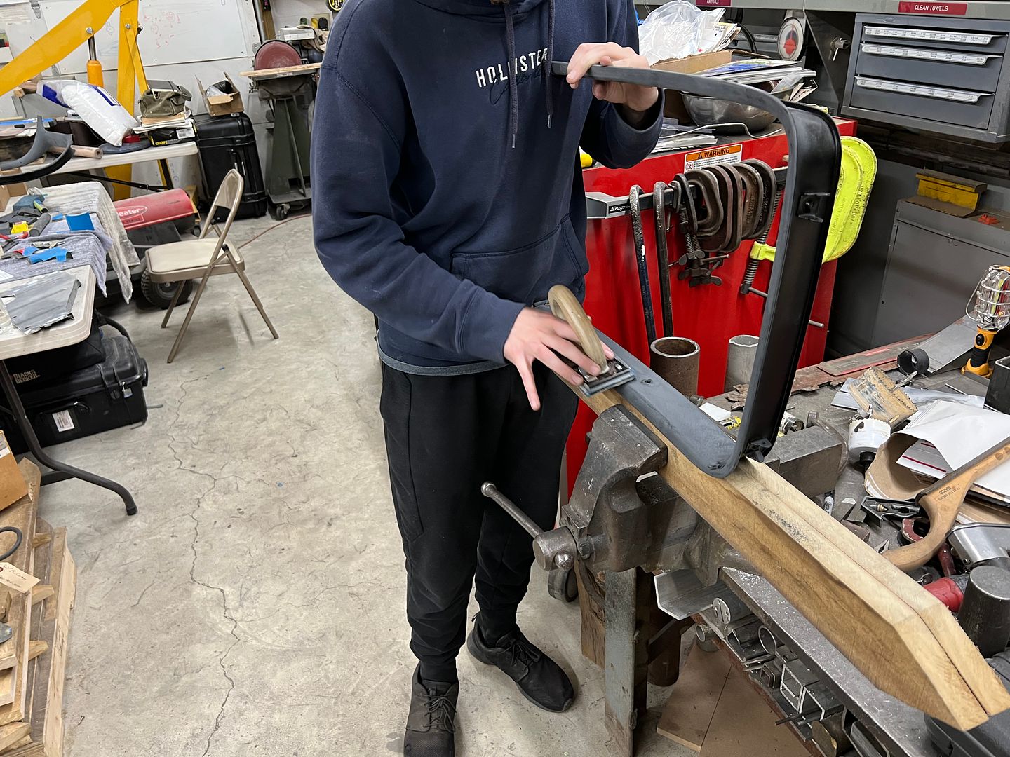
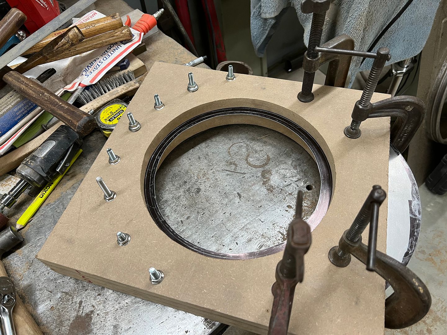
Our wire had been test fitted, sized, and tig welded together to form a continuous ring. This adds tremendous strength to the edge and helps to maintain a concentric circle. The wire was then cleaned as well. SPI epoxy was hand applied (acid brush) to the channel, the wire ring pressed in place (it was that tight) and then any bare spots on the ring epoxied as well..
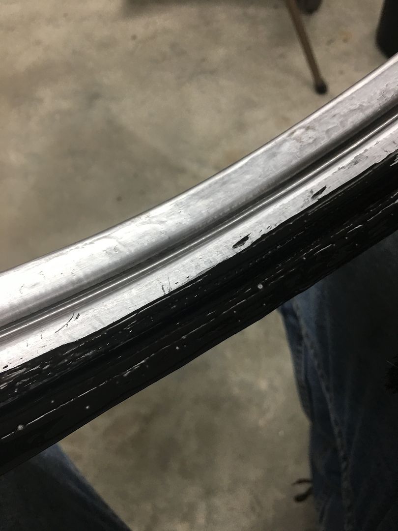
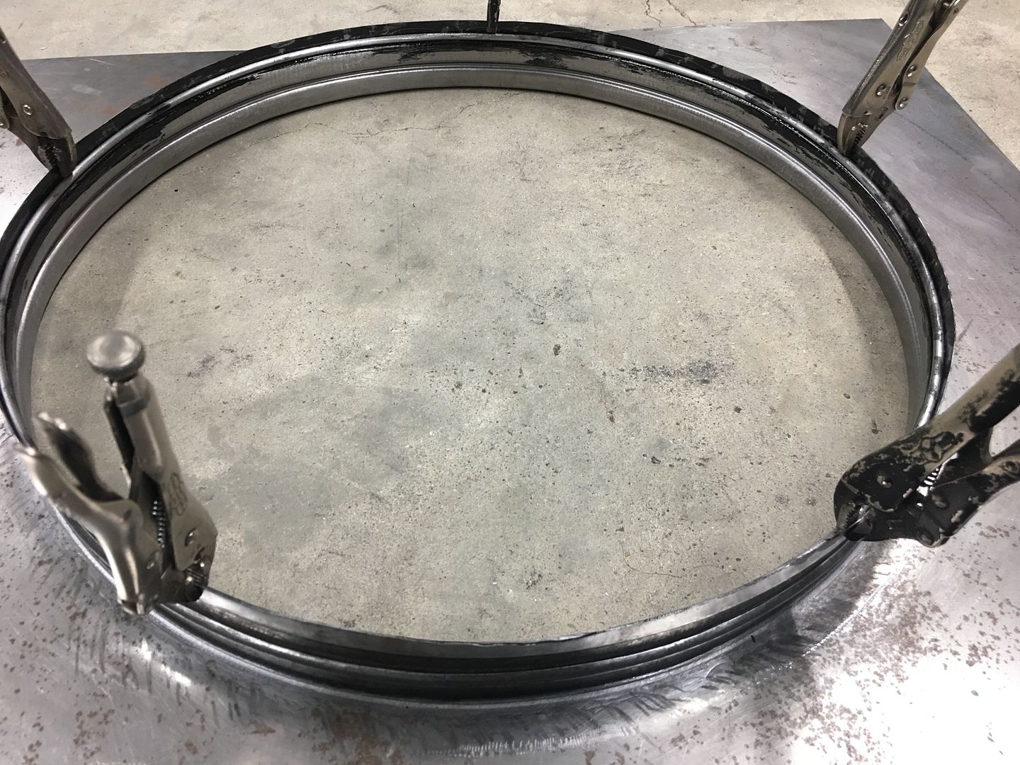
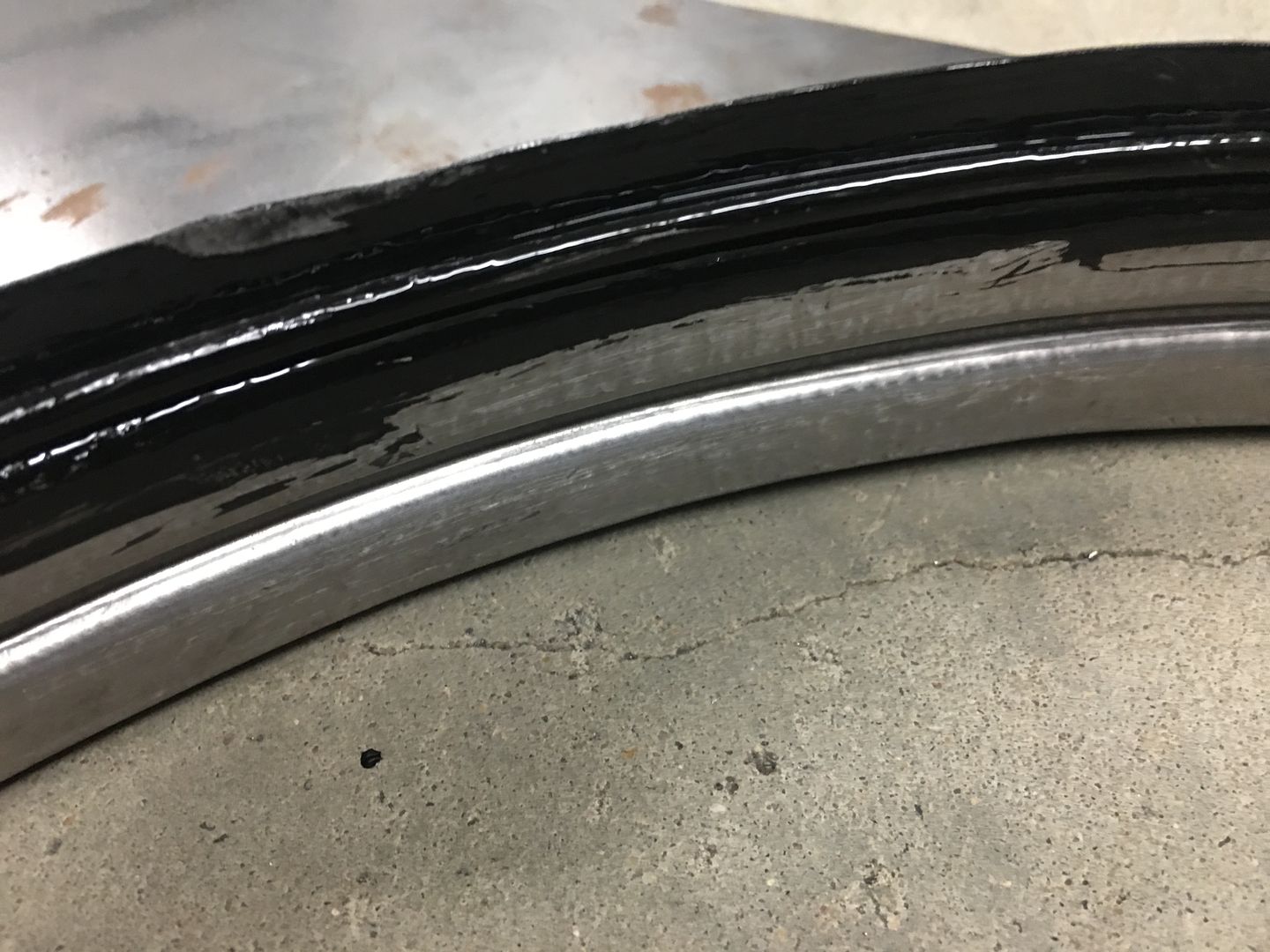
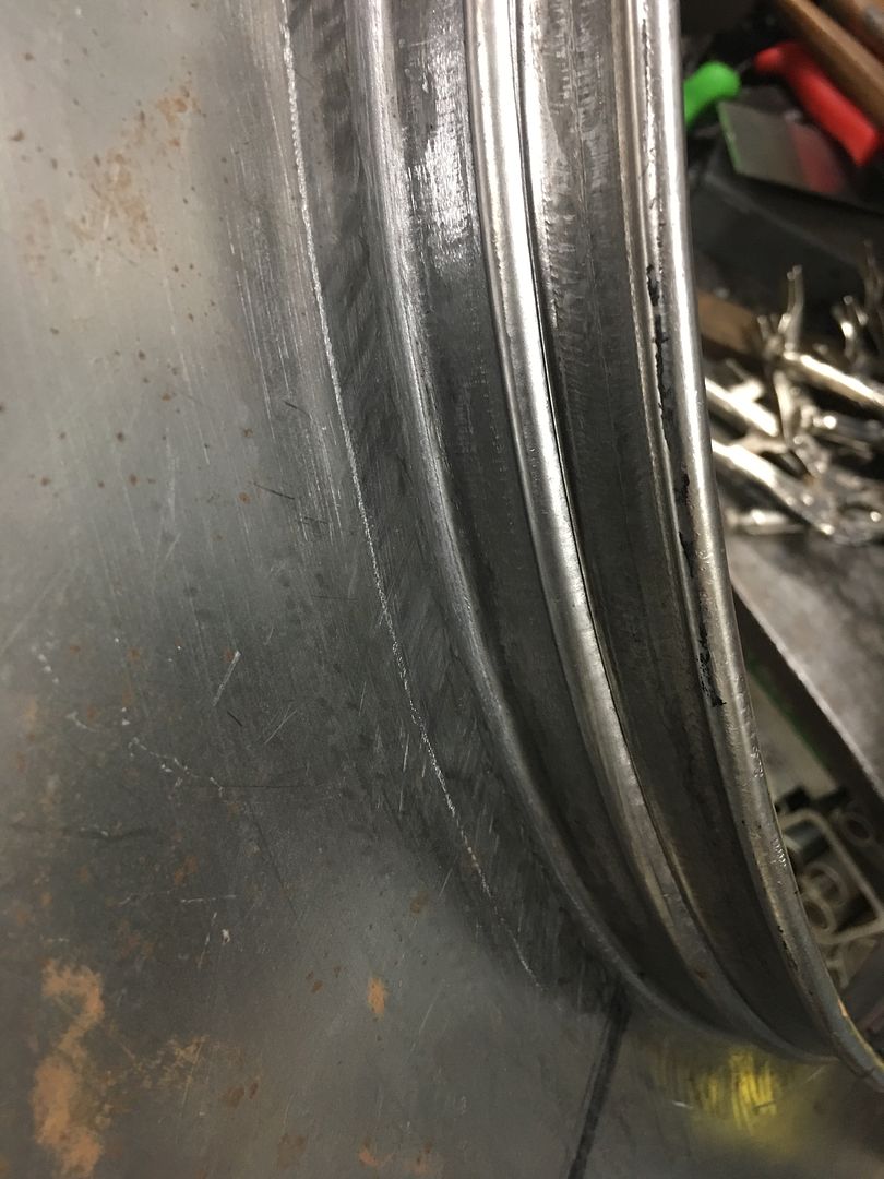
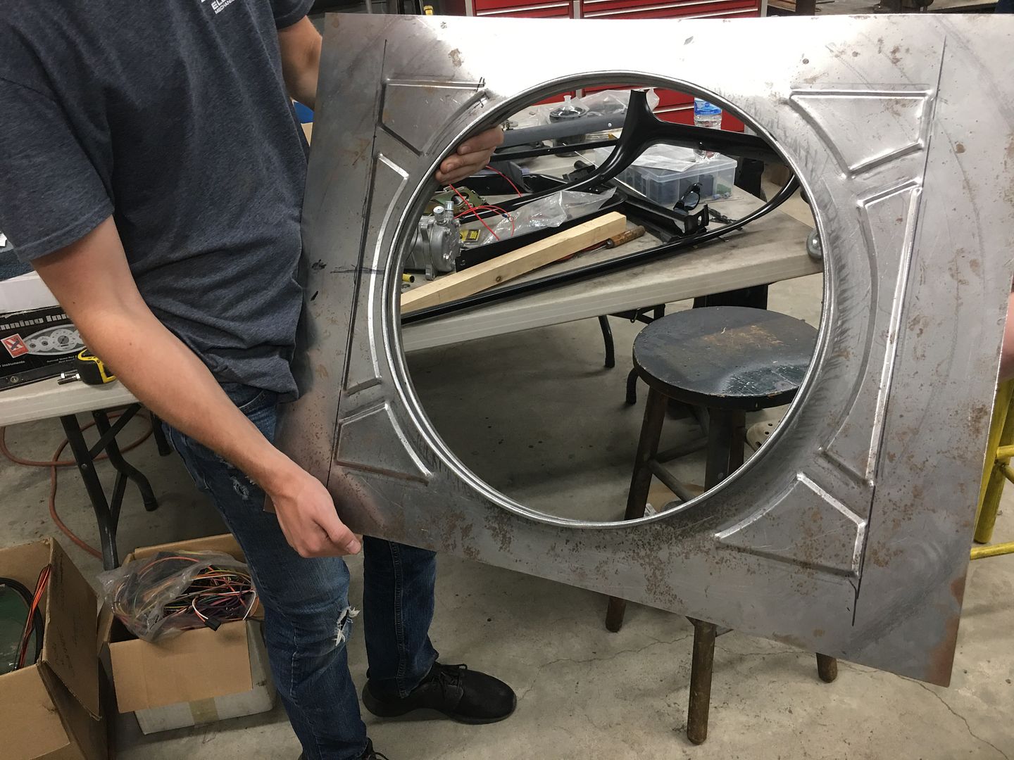
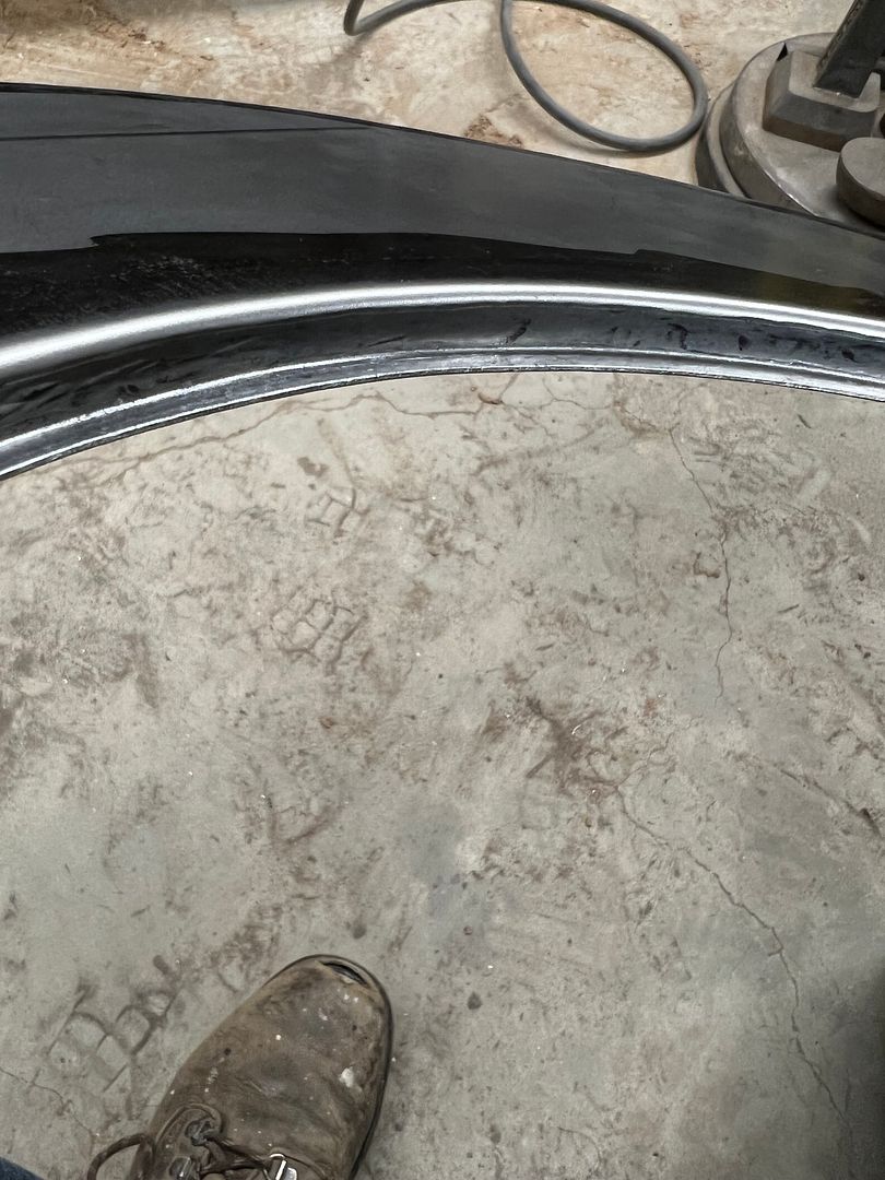
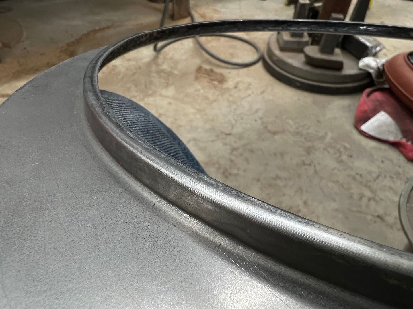
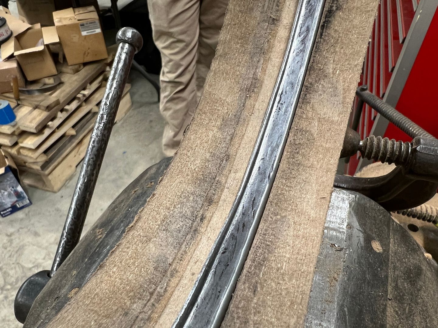
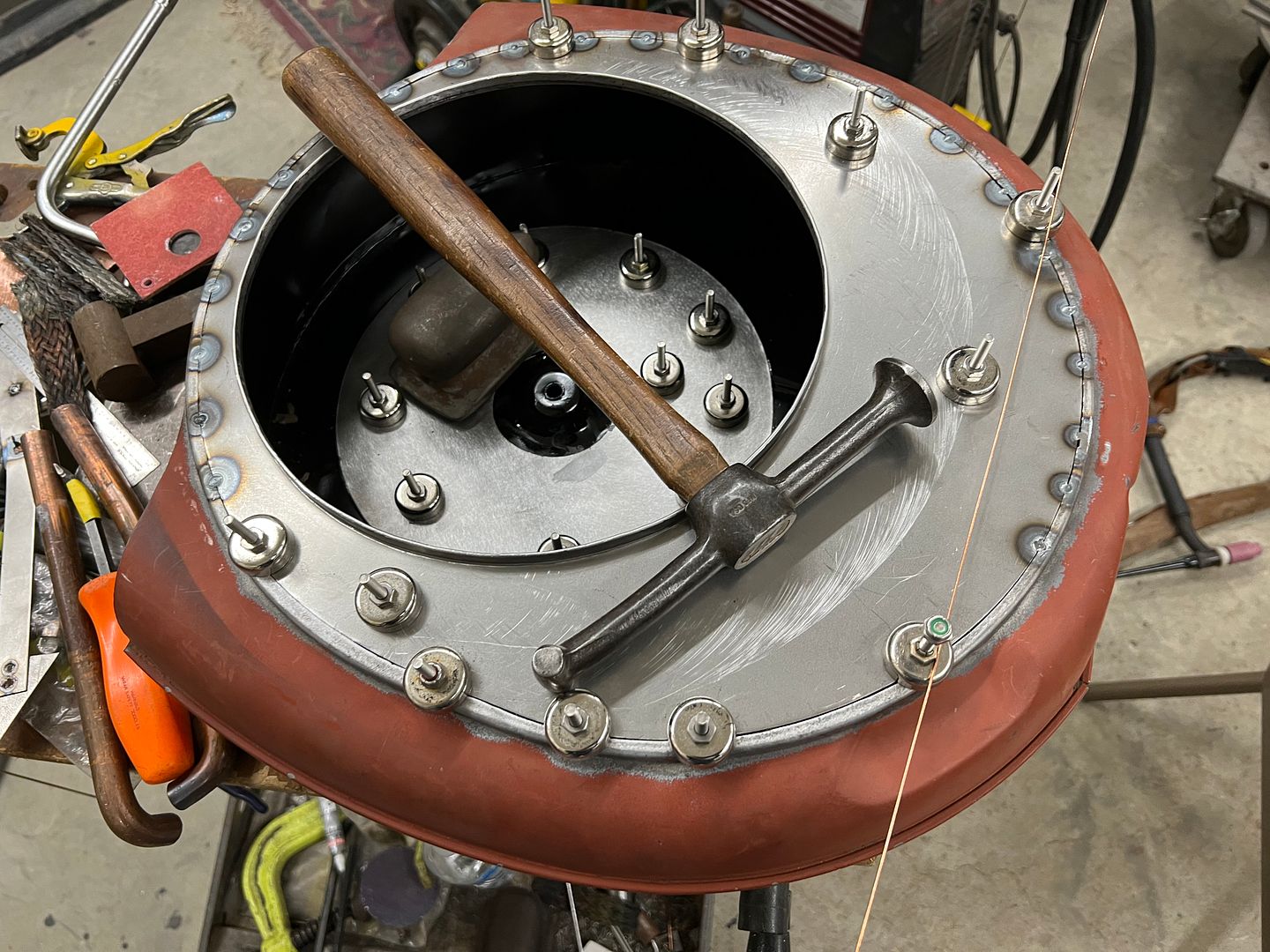
The vise grips hold the wire snug to the bottom of the channel until the edge of the flange can be staked in place. Wire edging process, done using our cone anvil, various hammers, and a 90 durometer polyurethane pad for the final closure of the wrap..
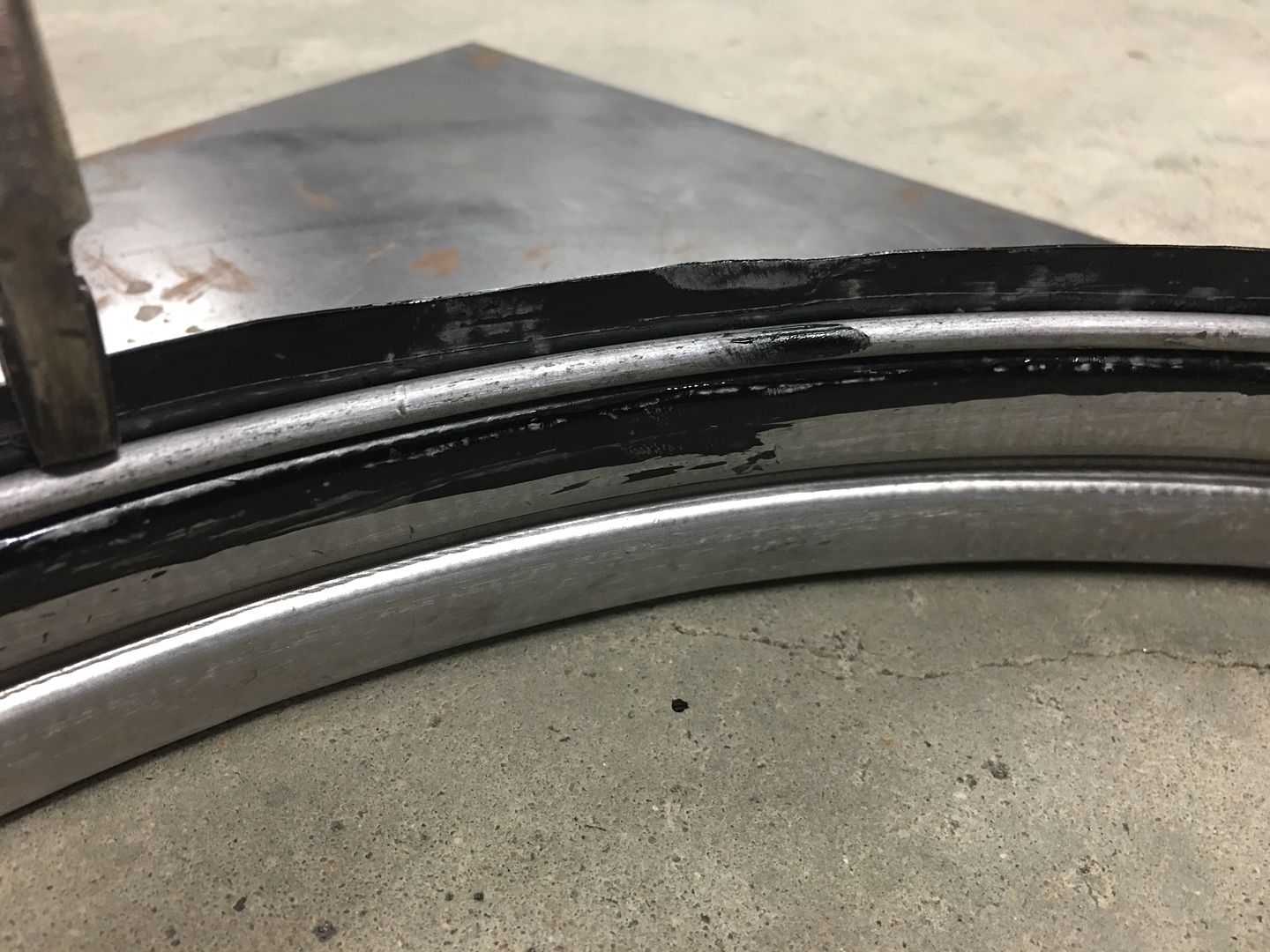
At the point we were hammering, the epoxy had set up approx 10-15 minutes, so it was not dry yet, but not running either. We'll let the epoxy set a couple days and get additional coats in the slight gap at the edge of the wrap in order to seal things well for rust prevention.
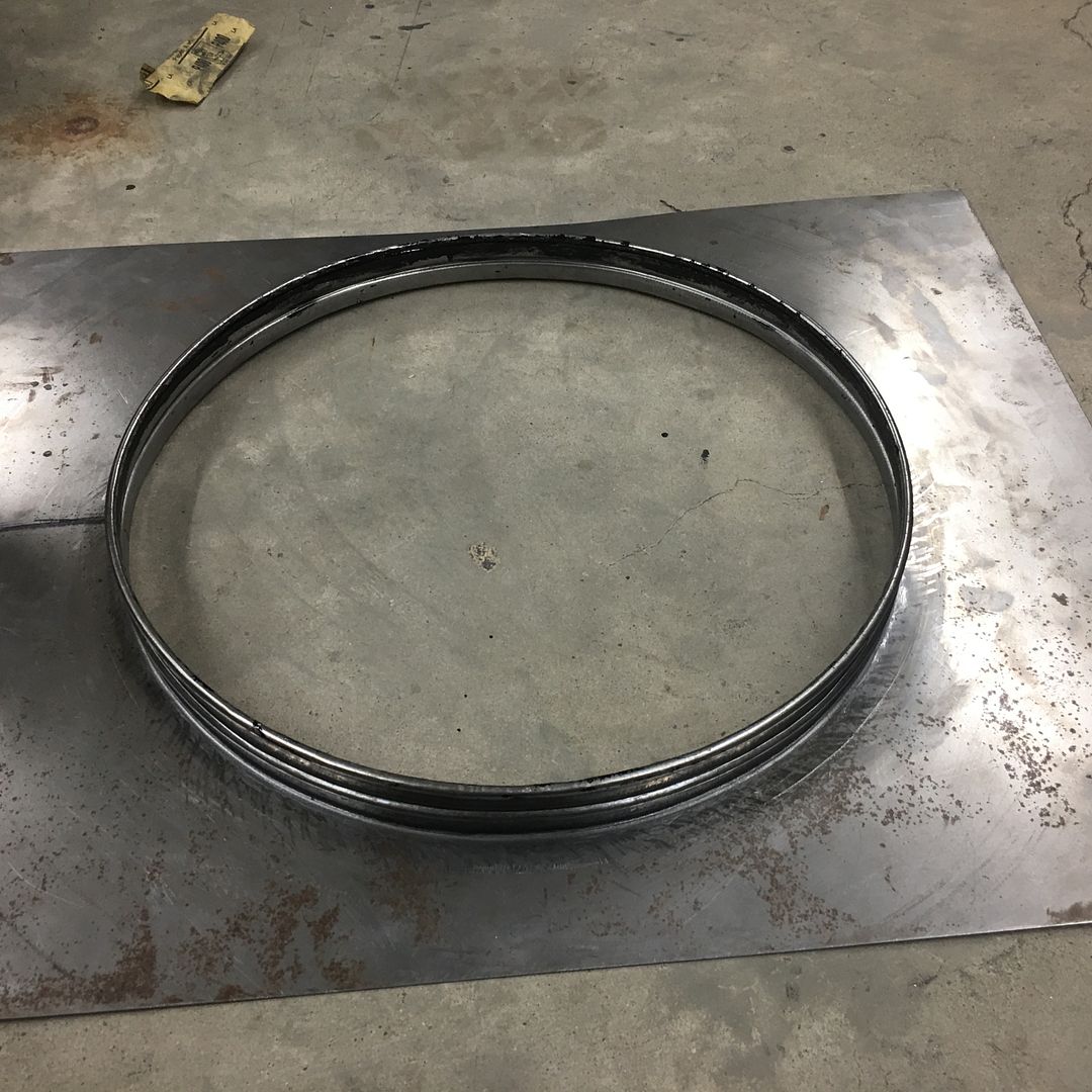
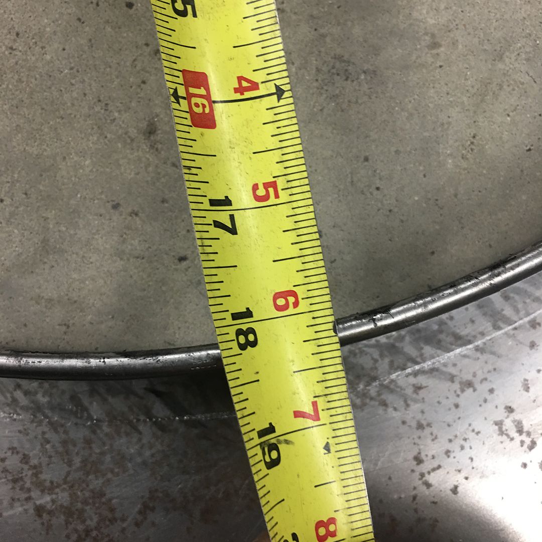
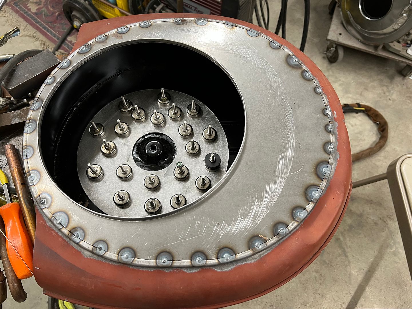
And our inside dimension worked out to what we were looking for, 18-1/8 diameter for our 17-1/4 fan blade.
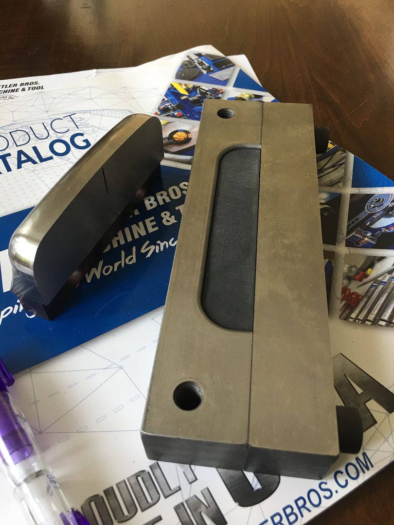
We also got another delivery, some 4" louver dies from Mittler Bros Machine and Tool for another job coming up. Will have to sneak it in here on some wagon parts as well.
I don't know who the young man is that's assisting you but, I hope he's paying attention. He's getting hands on experience that could last him a life time.
I have two guys helping out, one is a Jet mechanic and the other just graduated high school with plans on a Mechanical Engineering degree.
More progress on the fan shroud... Wire edging!! In order to stave off any rust issue as long as we can, I normally treat the wire channel to epoxy primer from the inside-out. So we used a scotchbrite pad and some Ivory liquid in warm water to remove any last remnants of the WD40 used for the last shaping effort on the Lennox.
Our wire had been test fitted, sized, and tig welded together to form a continuous ring. This adds tremendous strength to the edge and helps to maintain a concentric circle. The wire was then cleaned as well. SPI epoxy was hand applied (acid brush) to the channel, the wire ring pressed in place (it was that tight) and then any bare spots on the ring epoxied as well..
The vise grips hold the wire snug to the bottom of the channel until the edge of the flange can be staked in place. Wire edging process, done using our cone anvil, various hammers, and a 90 durometer polyurethane pad for the final closure of the wrap..
At the point we were hammering, the epoxy had set up approx 10-15 minutes, so it was not dry yet, but not running either. We'll let the epoxy set a couple days and get additional coats in the slight gap at the edge of the wrap in order to seal things well for rust prevention.
And our inside dimension worked out to what we were looking for, 18-1/8 diameter for our 17-1/4 fan blade.
We also got another delivery, some 4" louver dies from Mittler Bros Machine and Tool for another job coming up. Will have to sneak it in here on some wagon parts as well.
MP&C
Member
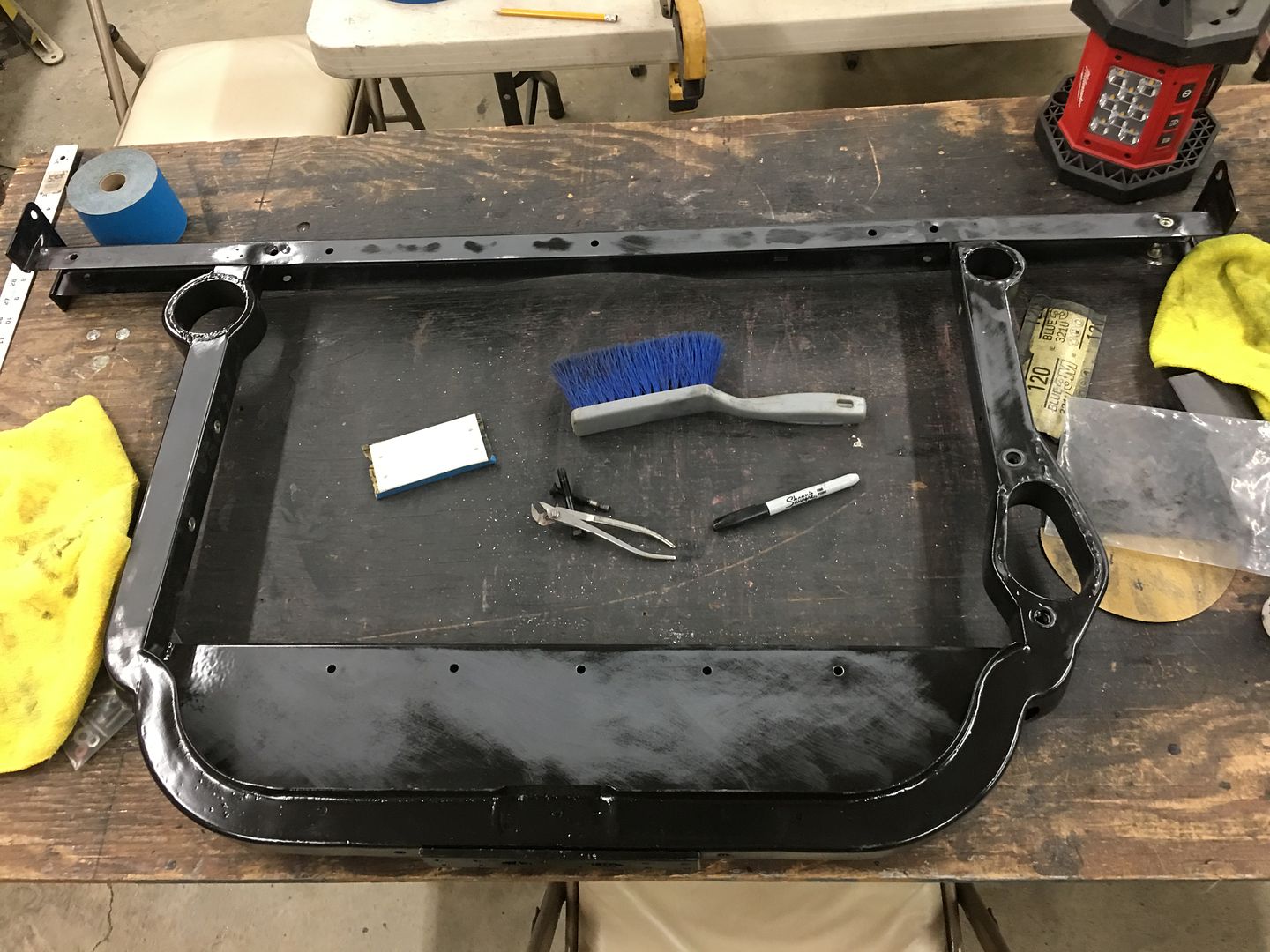
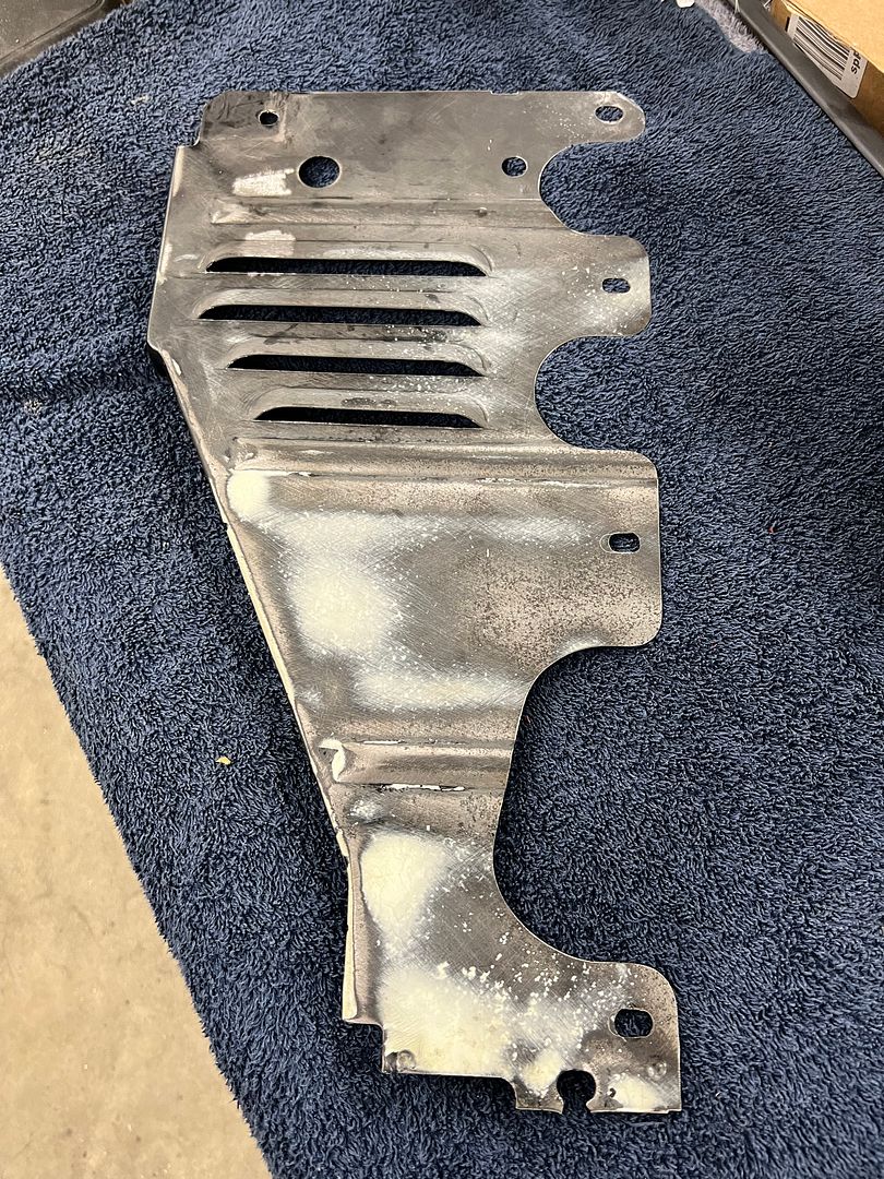
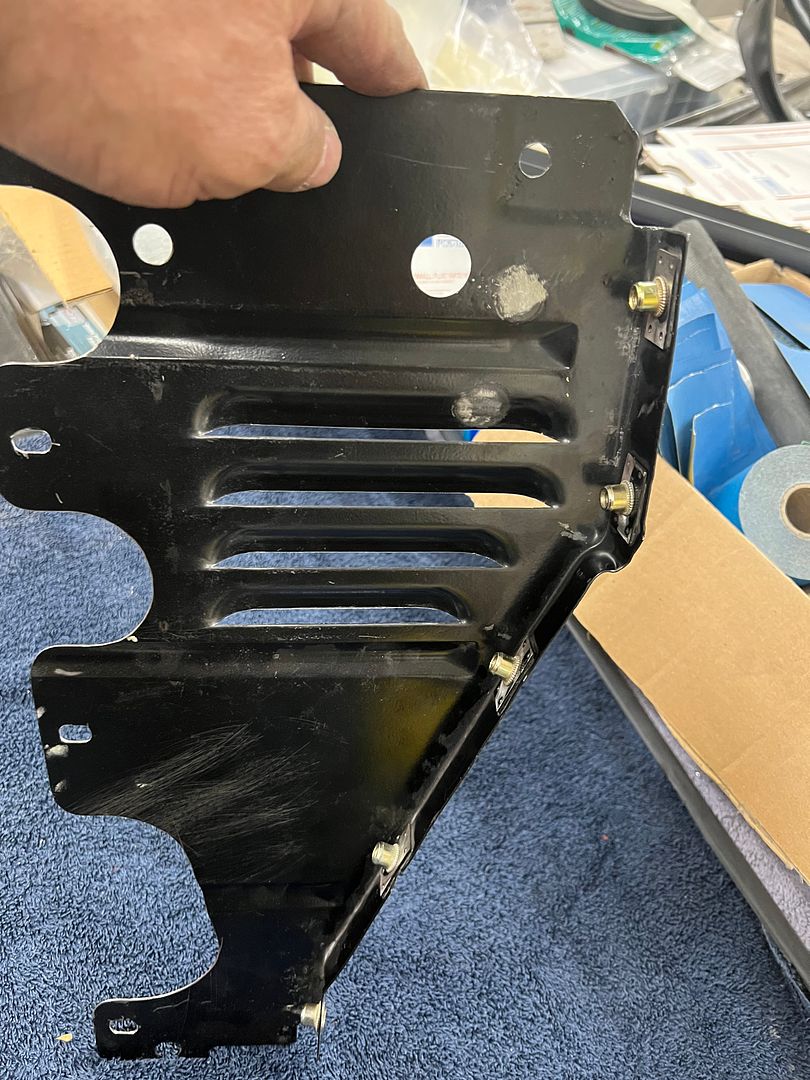
Looking at the fan shroud, the top and bottom will be stepped where it bolts behind the rear edge of the core support.
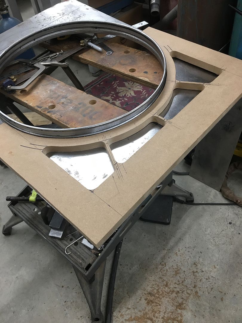
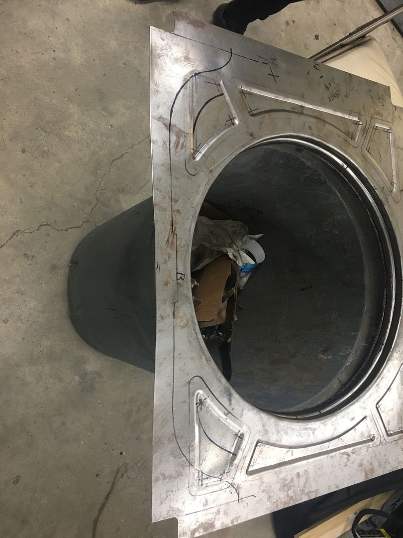
The sides will get a radius bend to bolt to the inside vertical of the core support. This still leave quite a bit of flat metal that just doesn't have much style to it. So let's try some embossing on the side panels.. To better keep things a consistent pattern from left to right, we made a pattern using MDF board..
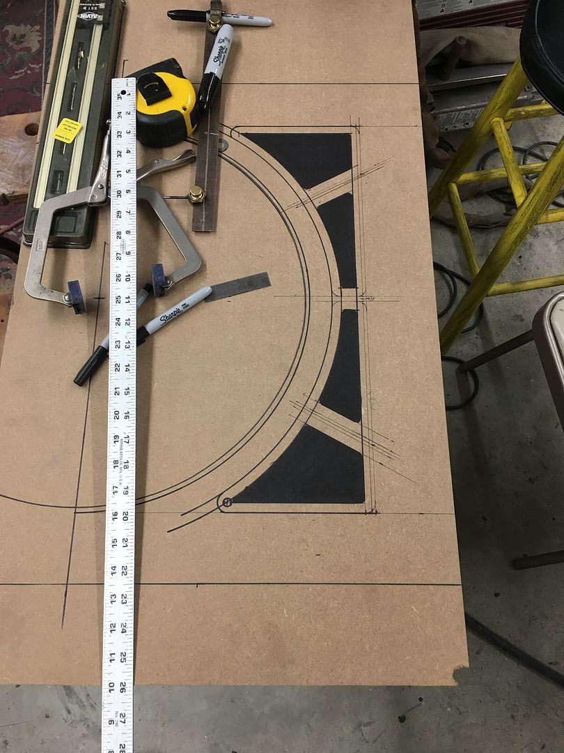
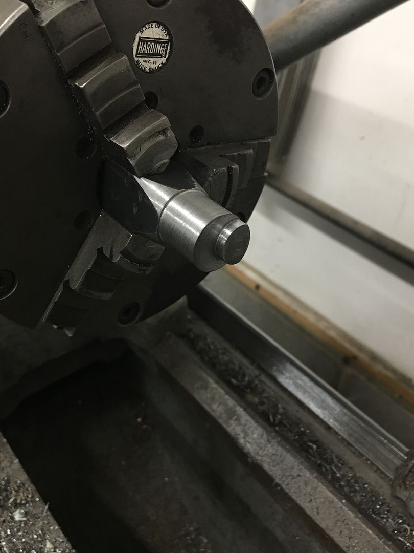
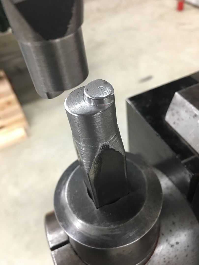
An offset die set is made in the Southbend lathe, the rounded sides will allow it to better travel along the pattern cutout.
We did a test run on our split original shroud, I had intended for the pattern to be inset when looking at the back.. Someone had the pattern clamped on the wrong side, and it was pressed outward instead.. Hindsight, when looking in the engine compartment from the side, the inset version would be more difficult to see the embossing, and this next "mistake" would be easier to see.
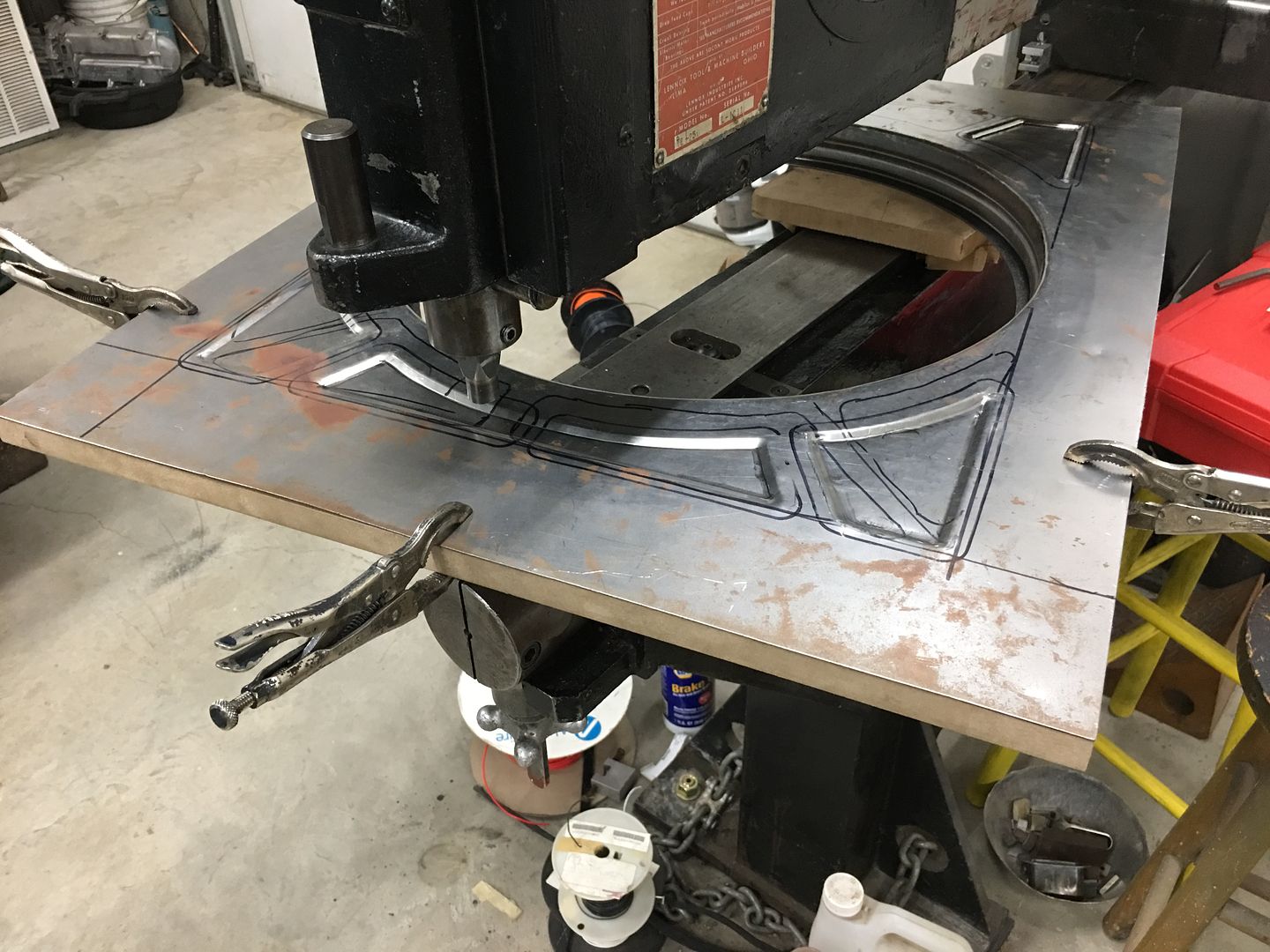
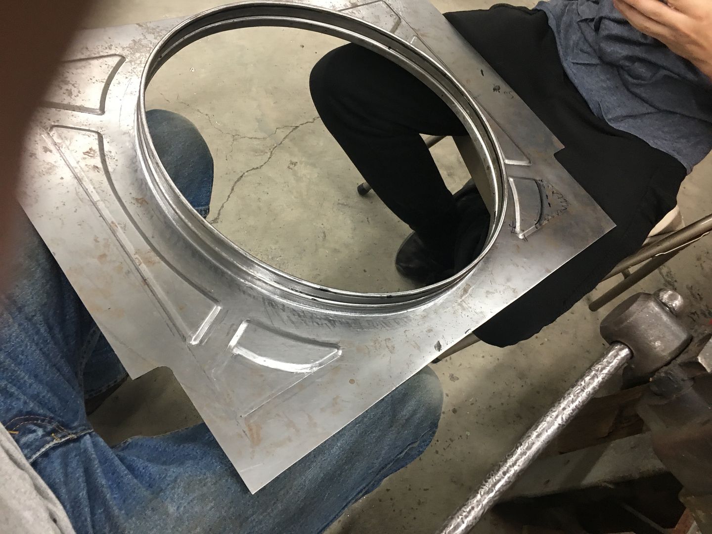
Sometimes things happen for a reason. So guess what we're going with.... The pattern did not have enough real estate to make a wide sweeping turn in the corners, so when using the dies we'll stop short of the corners and will coin them afterward by hand. Time lapse:
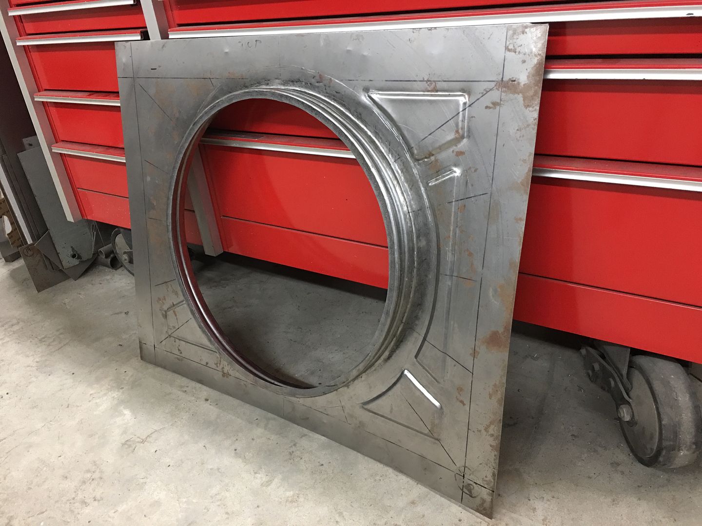
We did have one slip-up, should be an easy fix...
Looks a bit less blah now....
The sides will get a radius bend to bolt to the inside vertical of the core support. This still leave quite a bit of flat metal that just doesn't have much style to it. So let's try some embossing on the side panels.. To better keep things a consistent pattern from left to right, we made a pattern using MDF board..
An offset die set is made in the Southbend lathe, the rounded sides will allow it to better travel along the pattern cutout.
We did a test run on our split original shroud, I had intended for the pattern to be inset when looking at the back.. Someone had the pattern clamped on the wrong side, and it was pressed outward instead.. Hindsight, when looking in the engine compartment from the side, the inset version would be more difficult to see the embossing, and this next "mistake" would be easier to see.
Sometimes things happen for a reason. So guess what we're going with.... The pattern did not have enough real estate to make a wide sweeping turn in the corners, so when using the dies we'll stop short of the corners and will coin them afterward by hand. Time lapse:
We did have one slip-up, should be an easy fix...
Looks a bit less blah now....
MP&C
Member
Sorry for the hiatus, more travel for the day job.. hanging more TV's...
Back on the wagon, sometimes I get ahead of myself. The core support has rounded corners at the bottom....
Our embossing did not....
So the lower embossing was flattened, and marked for the new..
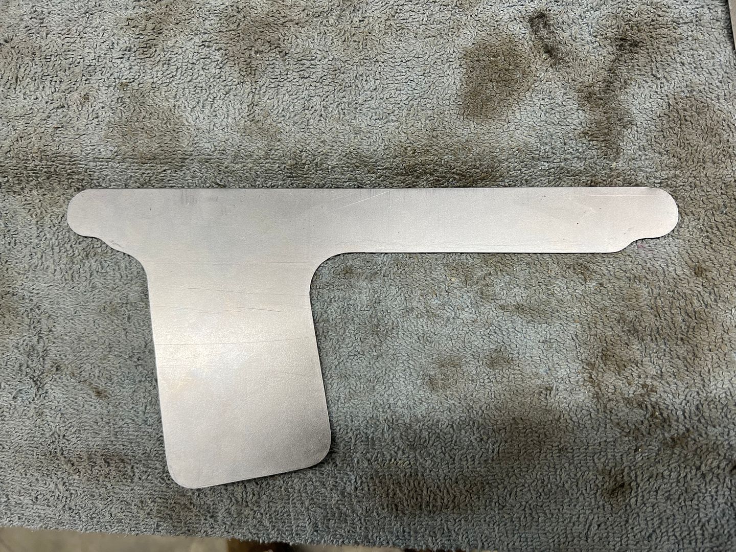
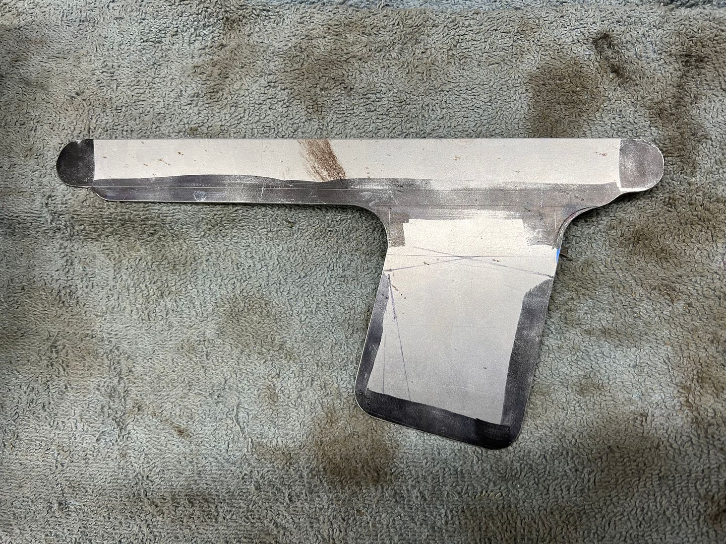
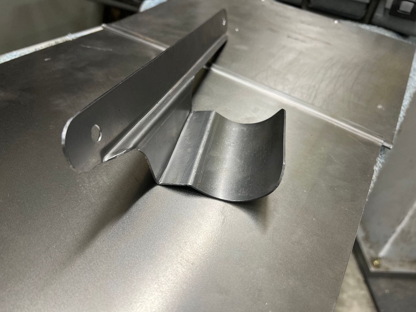
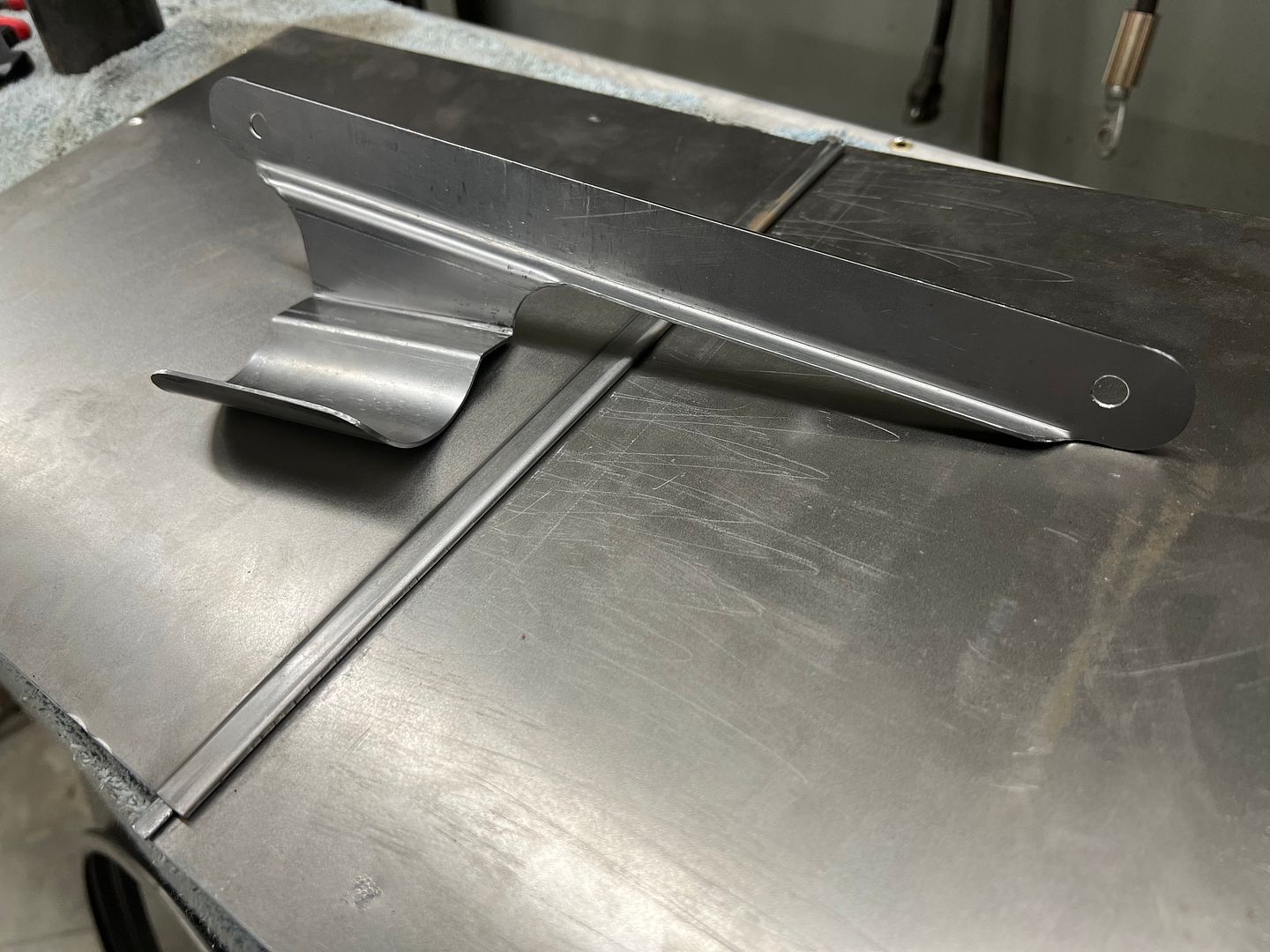
Next on the list, our upper radiator hose is a bit long and needed some support to keep it out of the fan. It's actually a lower hose for a Ford Explorer, but is a perfect fit for our cross flow radiator. So some 16 gauge cold rolled steel is used to fabricate a support bracket..
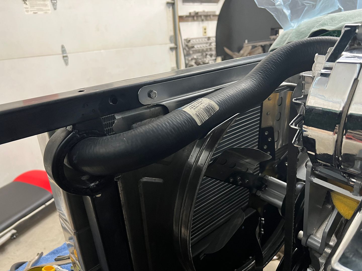
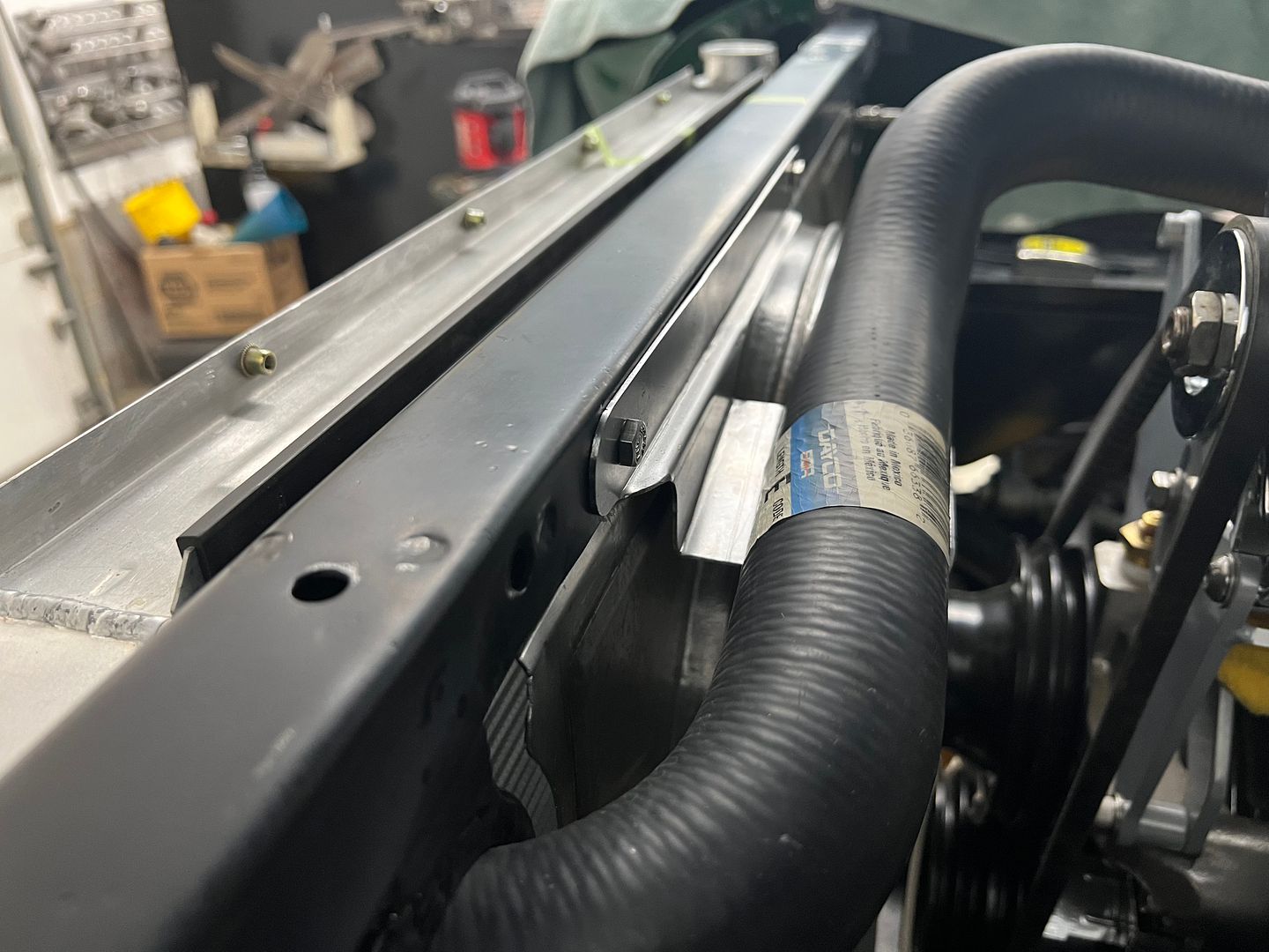
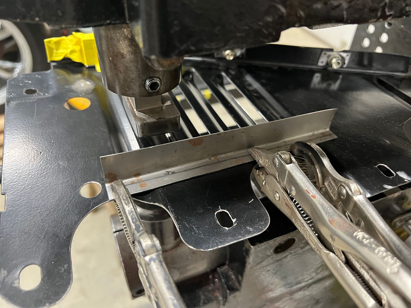
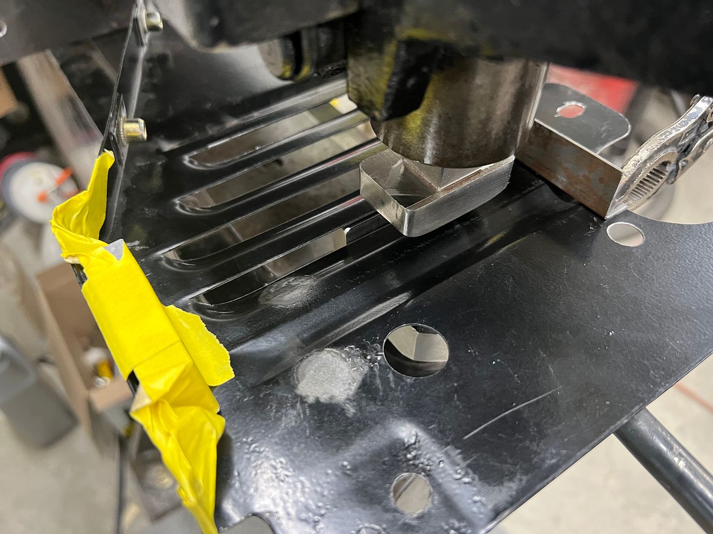
Next, we had moved the battery from the OEM location on the firewall to the dealer installed Air Conditioning location behind the core support. This has the battery in close proximity to the passenger side header, so we punched some louvers on the core supports side baffle to allow for air flow.
Back on the wagon, sometimes I get ahead of myself. The core support has rounded corners at the bottom....
Our embossing did not....
So the lower embossing was flattened, and marked for the new..
Next on the list, our upper radiator hose is a bit long and needed some support to keep it out of the fan. It's actually a lower hose for a Ford Explorer, but is a perfect fit for our cross flow radiator. So some 16 gauge cold rolled steel is used to fabricate a support bracket..
Next, we had moved the battery from the OEM location on the firewall to the dealer installed Air Conditioning location behind the core support. This has the battery in close proximity to the passenger side header, so we punched some louvers on the core supports side baffle to allow for air flow.
'68 Coronet R/T
Oldtimer
I know you mentioned it before but where do you get those nut inserts? Do they require a special tool?
Klleetrucking
Promoted Users
I know you mentioned it before but where do you get those nut inserts? Do they require a special tool?

McMaster-Carr
McMaster-Carr is the complete source for your plant with over 595,000 products. 98% of products ordered ship from stock and deliver same or next day.
MP&C
Member
Yes, I use McMaster for most of my hardware related items, most things deliver the next day if I order before 3 PM. Here is the series of rivet nuts I use, splined for less chance of spinning. Here are the tools they carry for installation, they work pretty well.
tool link:
 www.mcmaster.com
Most of these rivet nut sizes have a grip range available to accommodate typical body panel thickness.

tool link:
McMaster-Carr
McMaster-Carr is the complete source for your plant with over 595,000 products. 98% of products ordered ship from stock and deliver same or next day.
Most of these rivet nut sizes have a grip range available to accommodate typical body panel thickness.
MP&C
Member
Wagon progress! So Jared has been tackling the fun task of prepping interior trim pieces, getting them ready for another round of epoxy..
Another modification we're undertaking, the air cleaner, when mocked up on the engine, showed a tight proximity to the back of the AC compressor. Looking at the clearance we had to the firewall, moving backward 1" will give us much needed breathing room for the AC lines. So out with the old ....
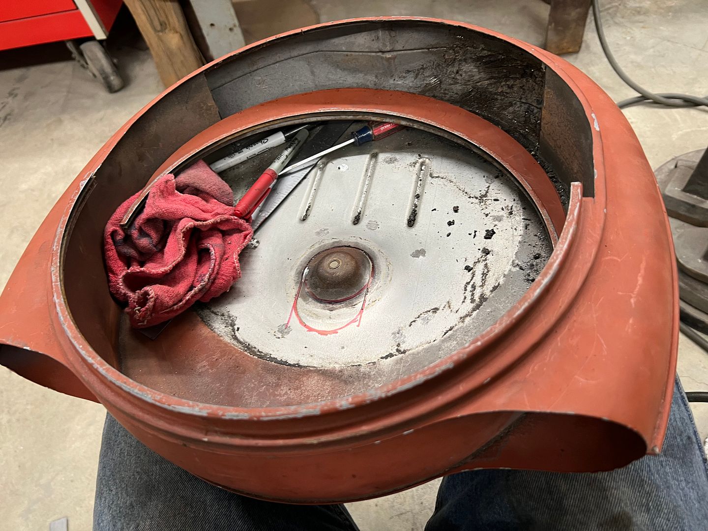
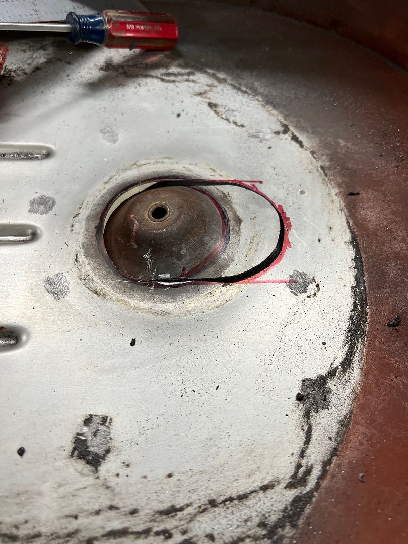
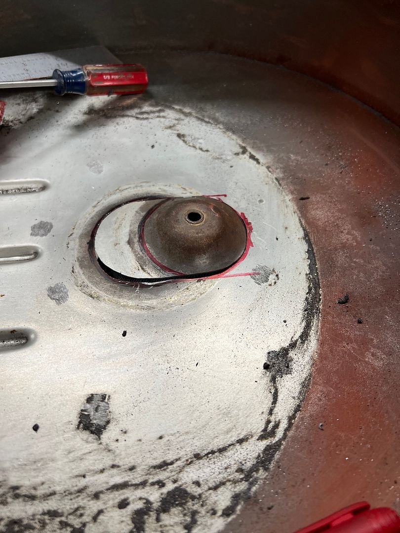
And to move rearward, the mounting hole is moved forward one inch..
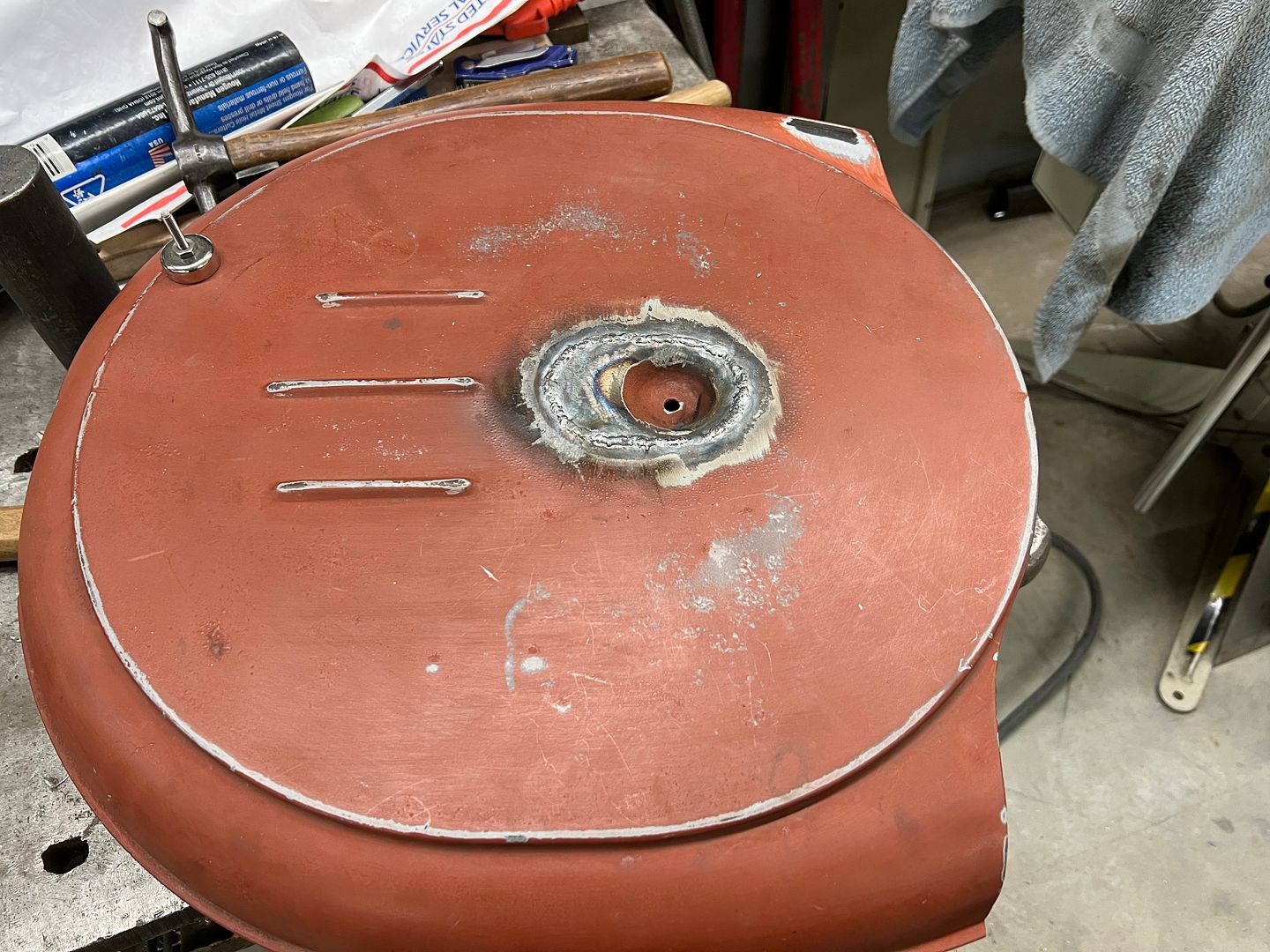
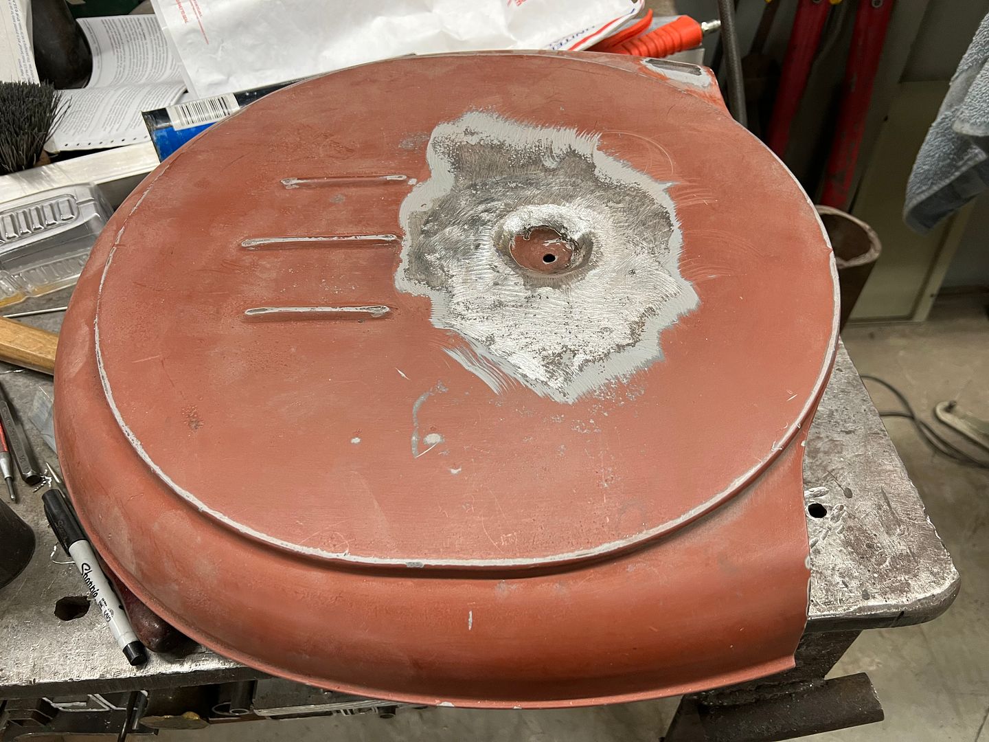
Next in store is a new bottom for the air cleaner..
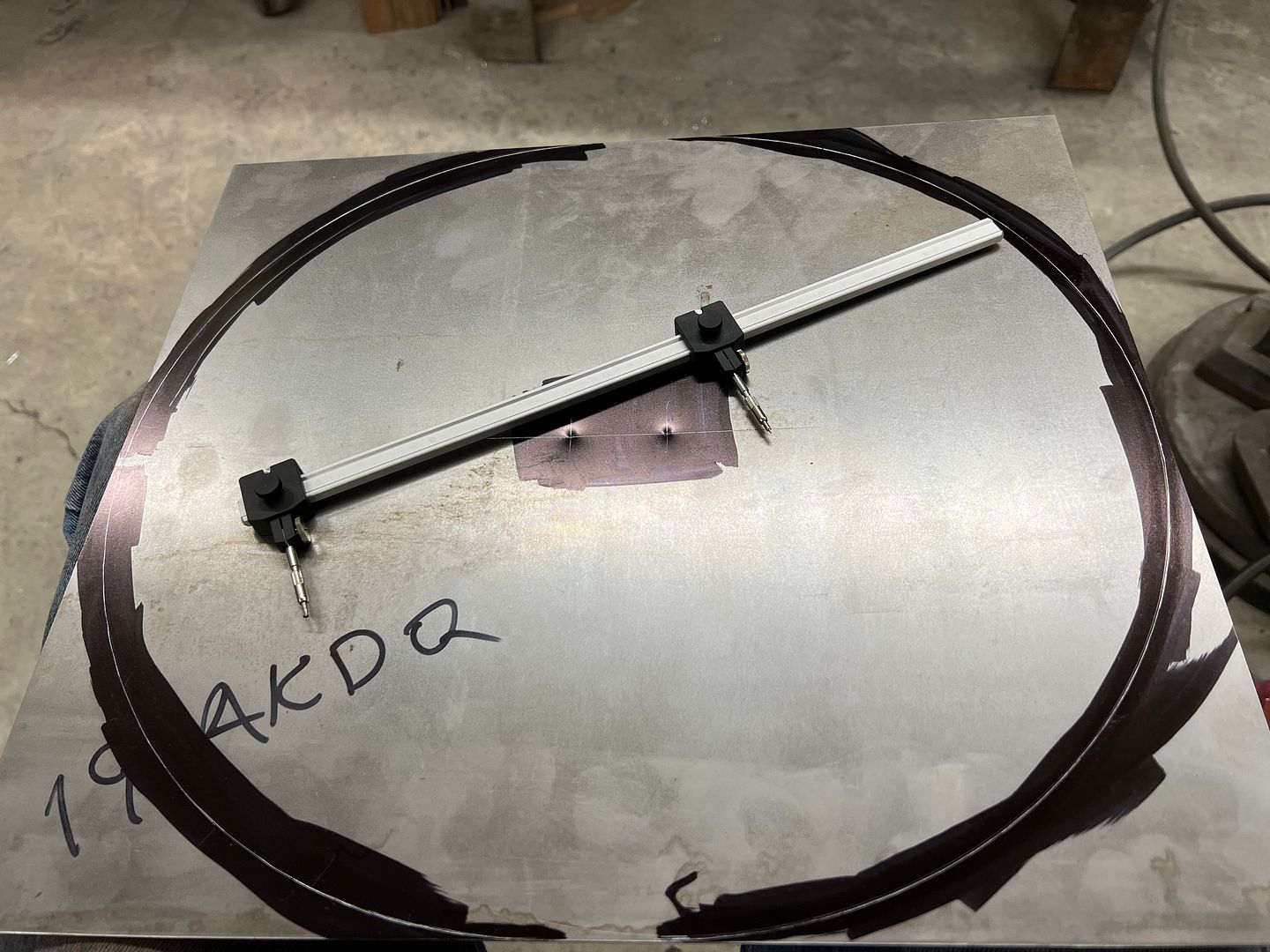
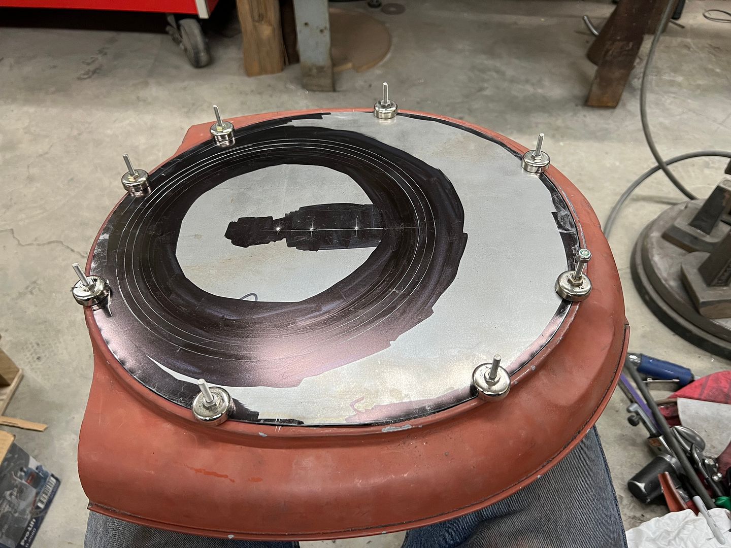
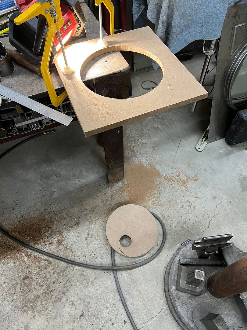
A hammerform is used to give us a folded lip out the bottom
Another modification we're undertaking, the air cleaner, when mocked up on the engine, showed a tight proximity to the back of the AC compressor. Looking at the clearance we had to the firewall, moving backward 1" will give us much needed breathing room for the AC lines. So out with the old ....
And to move rearward, the mounting hole is moved forward one inch..
Next in store is a new bottom for the air cleaner..
A hammerform is used to give us a folded lip out the bottom
MP&C
Member
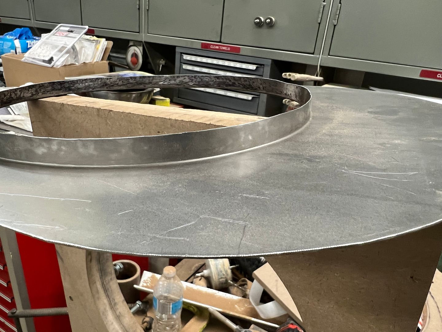
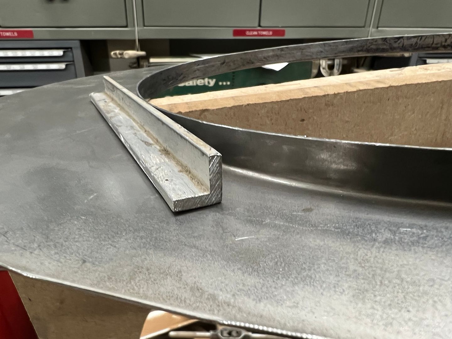
At this point we need to hem the flange so the bottom isn't quite so sharp..
A 1/2 x 1/2 aluminum angle is used as a height gauge so we can use the roloc sander to get our flange to a consistent height. This will allow us to use a tipping die in the bead roller to fold the hem..
Then the part is re-installed in the hammer form to hammer the hem flat..
A 1/2 x 1/2 aluminum angle is used as a height gauge so we can use the roloc sander to get our flange to a consistent height. This will allow us to use a tipping die in the bead roller to fold the hem..
Then the part is re-installed in the hammer form to hammer the hem flat..
MP&C
Member
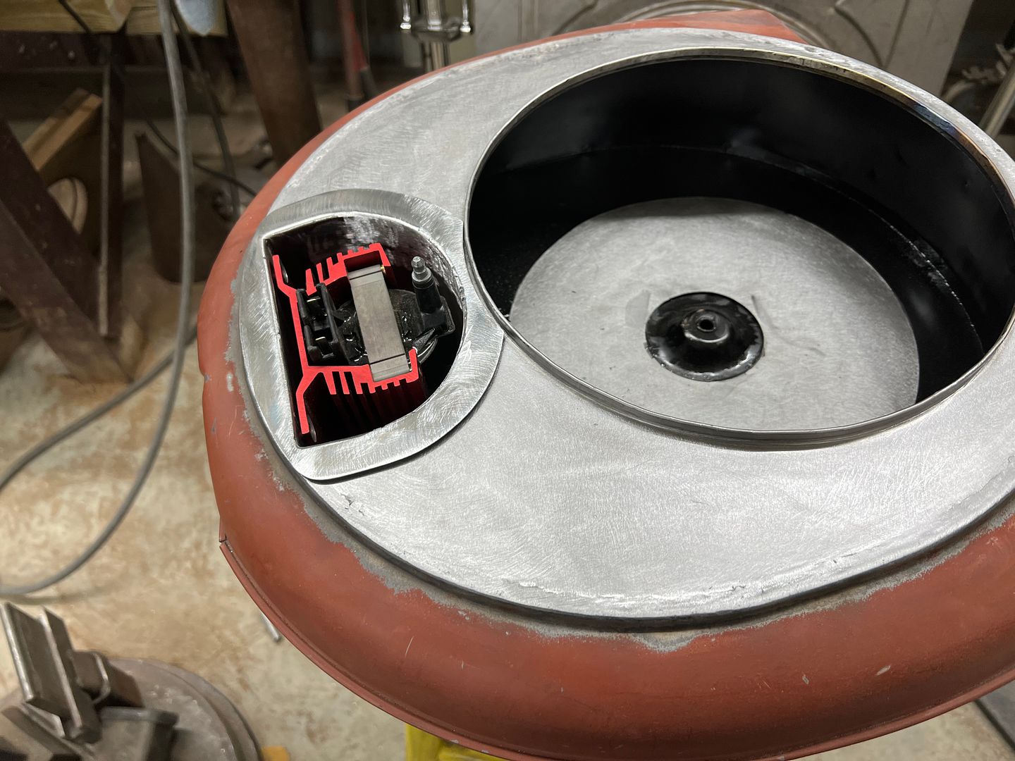
So I've had some questions as to why this or that with modifying the air cleaner. I was going to hold out with the REAL reason, but here goes.... This firewall is just too clean that I can't bring myself to clutter it up (or the wheelwell) by mounting an ignition coil and then being forced into using an overly long coil wire..
.JPG)
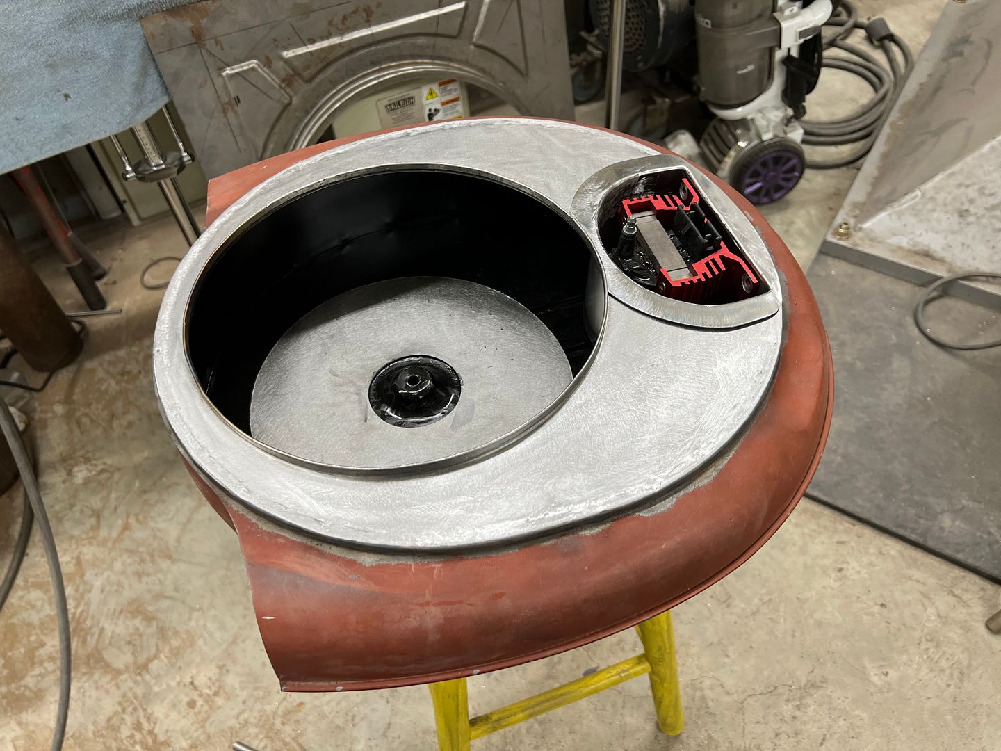
So as shown here.... this will be the approximate location as we fabricate a sealed cavity from the bottom side of the air cleaner to mount the coil. This should put the coil wire about two inches in front of the distributor...
.JPG)
So this should give us a nice clean look and keep the firewall as open as we can...
So as shown here.... this will be the approximate location as we fabricate a sealed cavity from the bottom side of the air cleaner to mount the coil. This should put the coil wire about two inches in front of the distributor...
So this should give us a nice clean look and keep the firewall as open as we can...
MP&C
Member
I've seen coils mounted directly to the intake and all the heat convection that would entail. The air cleaner should remain somewhat cool given the air flow through it. When I say sealed, I mean to the inside of the housing, there will be a gaping hole to the bottom. But if need be we can add some directional vanes or air tubes to promote air flow up into the cavity.
dhutton01
Backyard Hack
I would be tempted to have openings top and bottom so engine vacuum could pull air over the coil fins. High temperature is the enemy of electronic compnents. The higher the temperature the lower the reliability. The fins tell me that coil dissipates a lot of power and runs very hot…
Don
Don
Robert, there is a new tool that is almost like a palm held power hammer that would have saved you a lot of time on that hammer form. Its called EZ Hammer, and also works good on weld seams, with or without easy access, check it out. May have to make a larger head for working on dents though. It has a built in regulator on the tool.
MP&C
Member
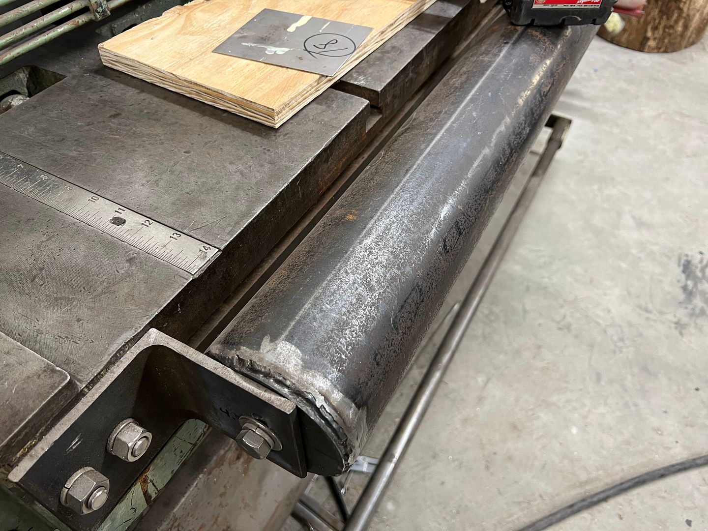
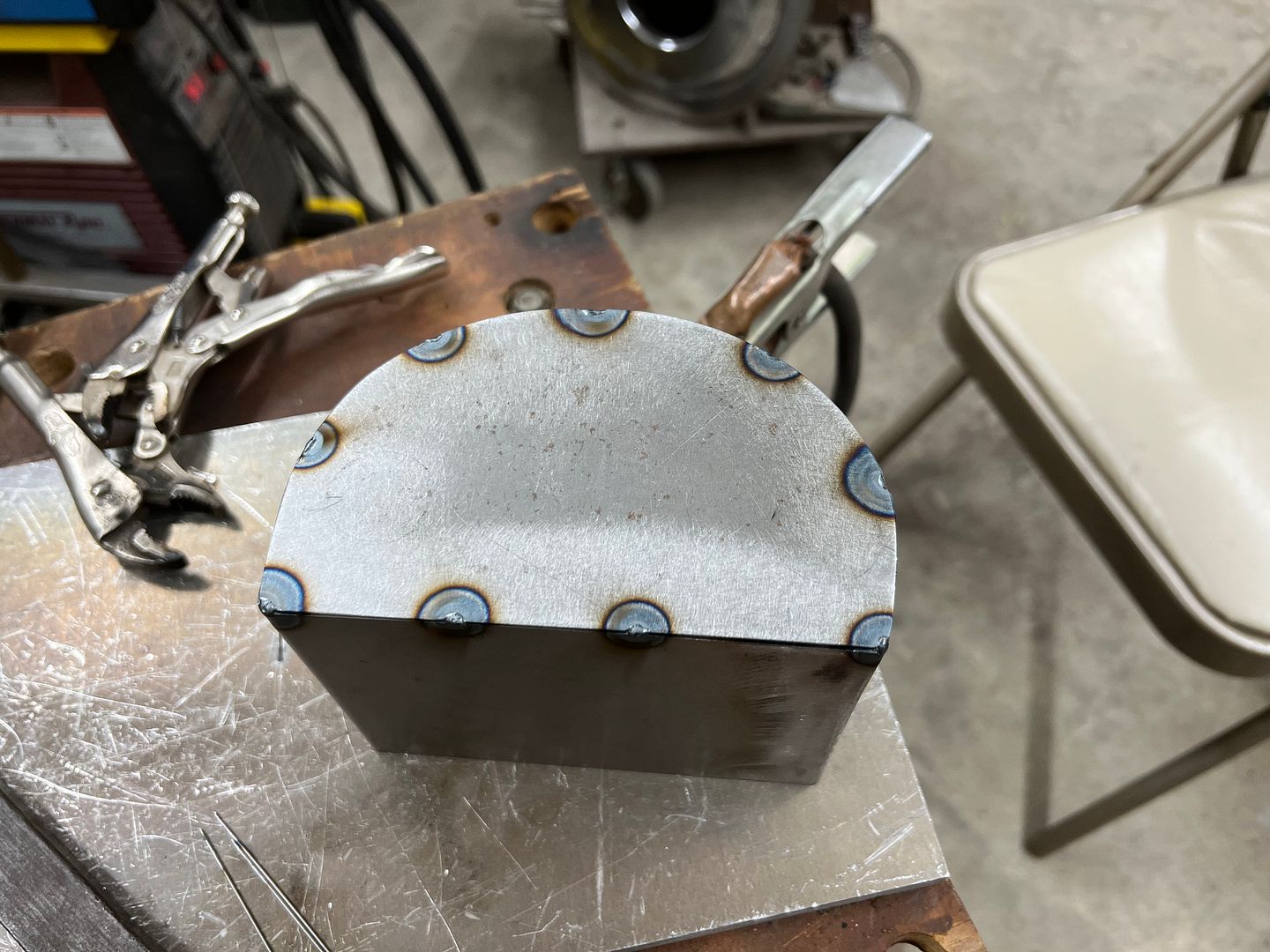
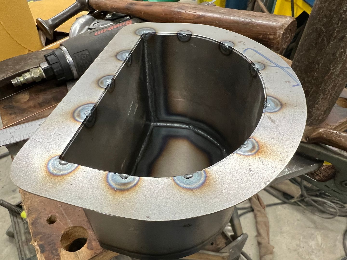
More work on the Caddy air cleaner, time to fabricate the pocket for the coil. Our radius brake that is bolted to the front of the shear is used to bend some 18ga into a horseshoe. One side is trimmed short and the other is left long to bend and form the bottom in the magnetic brake.
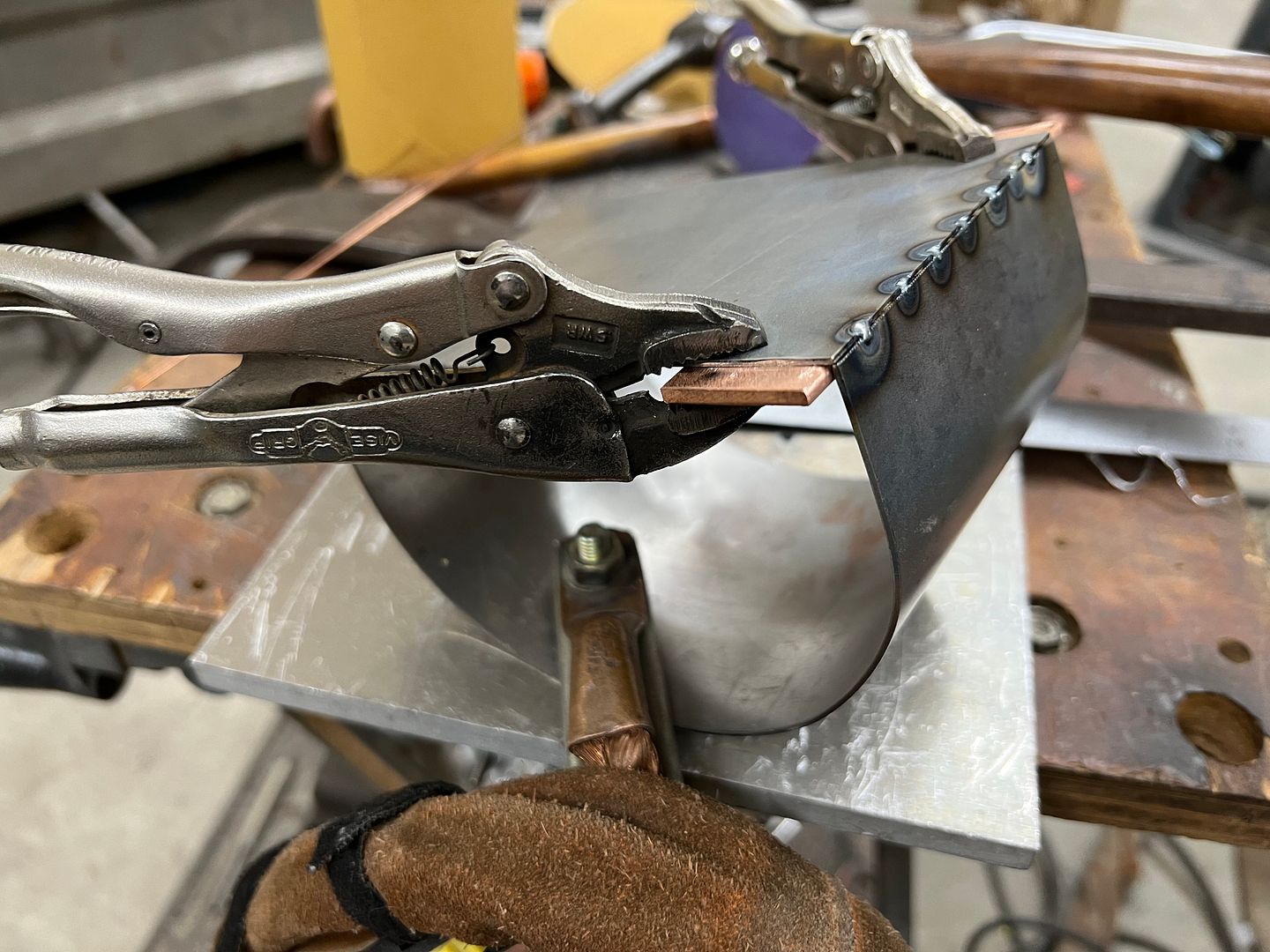
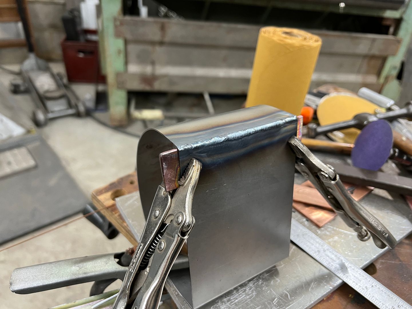
And end plate is cut out to seal off the void from the rest of the air cleaner innards. This gets tacked in place and then fusion welded using the TIG.
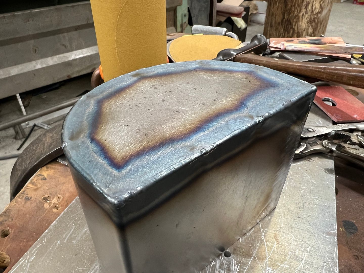
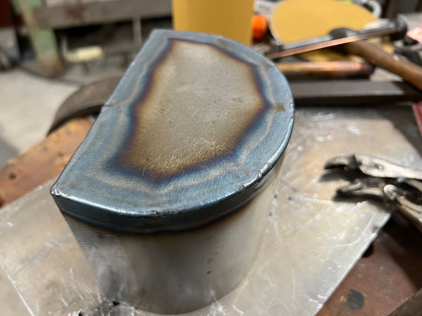
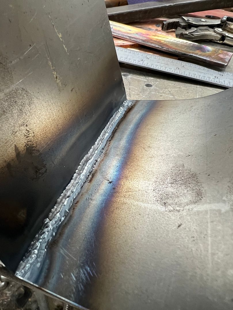
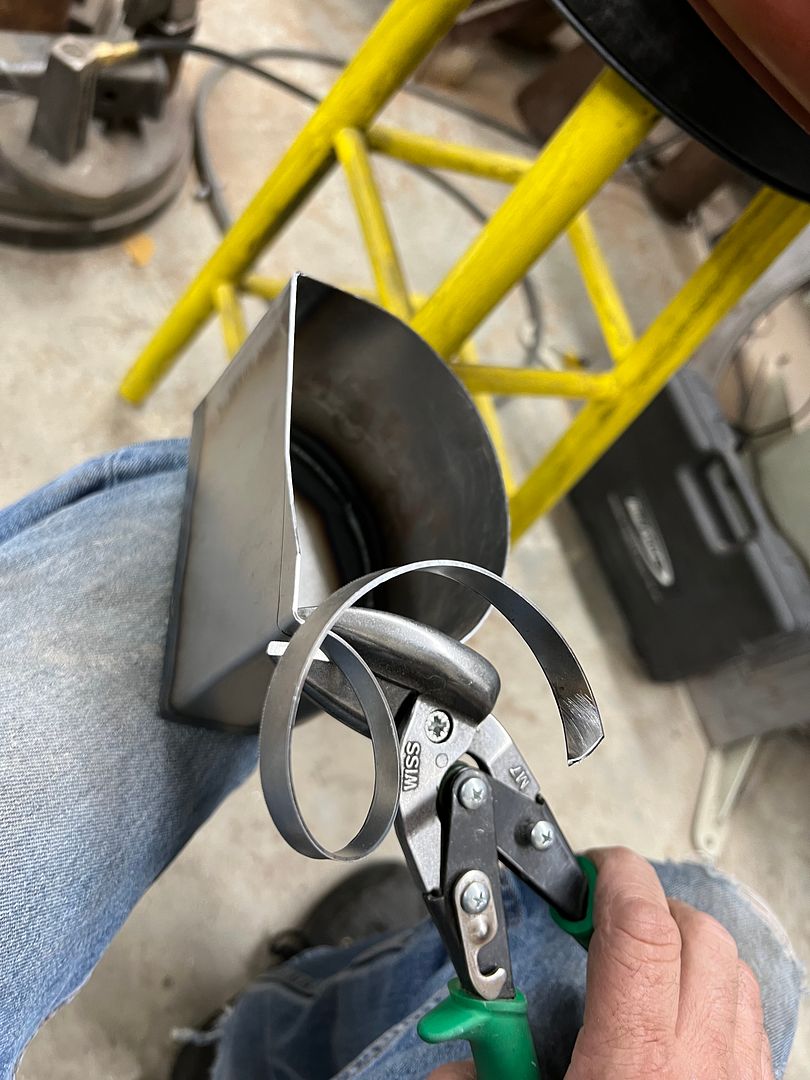
A holesaw is used to get the hole started and offset Wiss snips to trim out the hole in both the housing and the mounting flange. TIG tacked and fusion welding on the flange, and it then gets trimmed to fit inside the air cleaner housing.
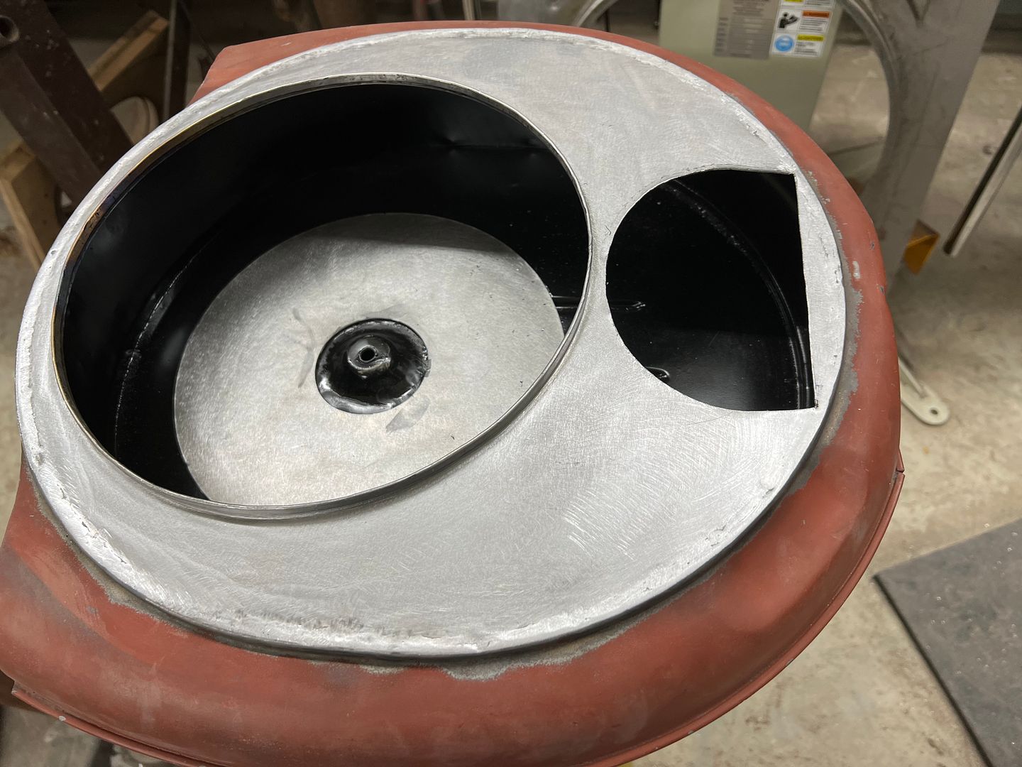
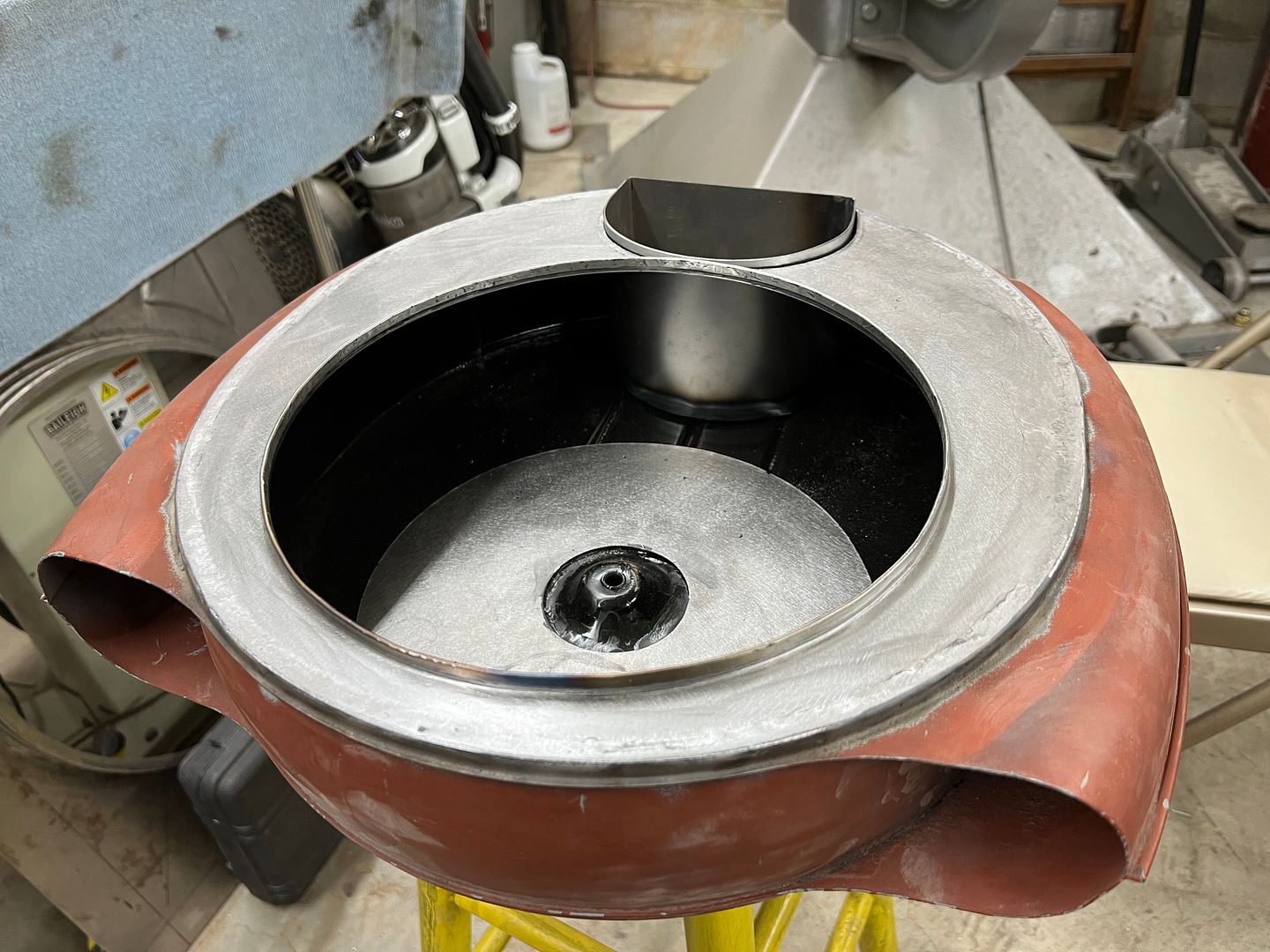
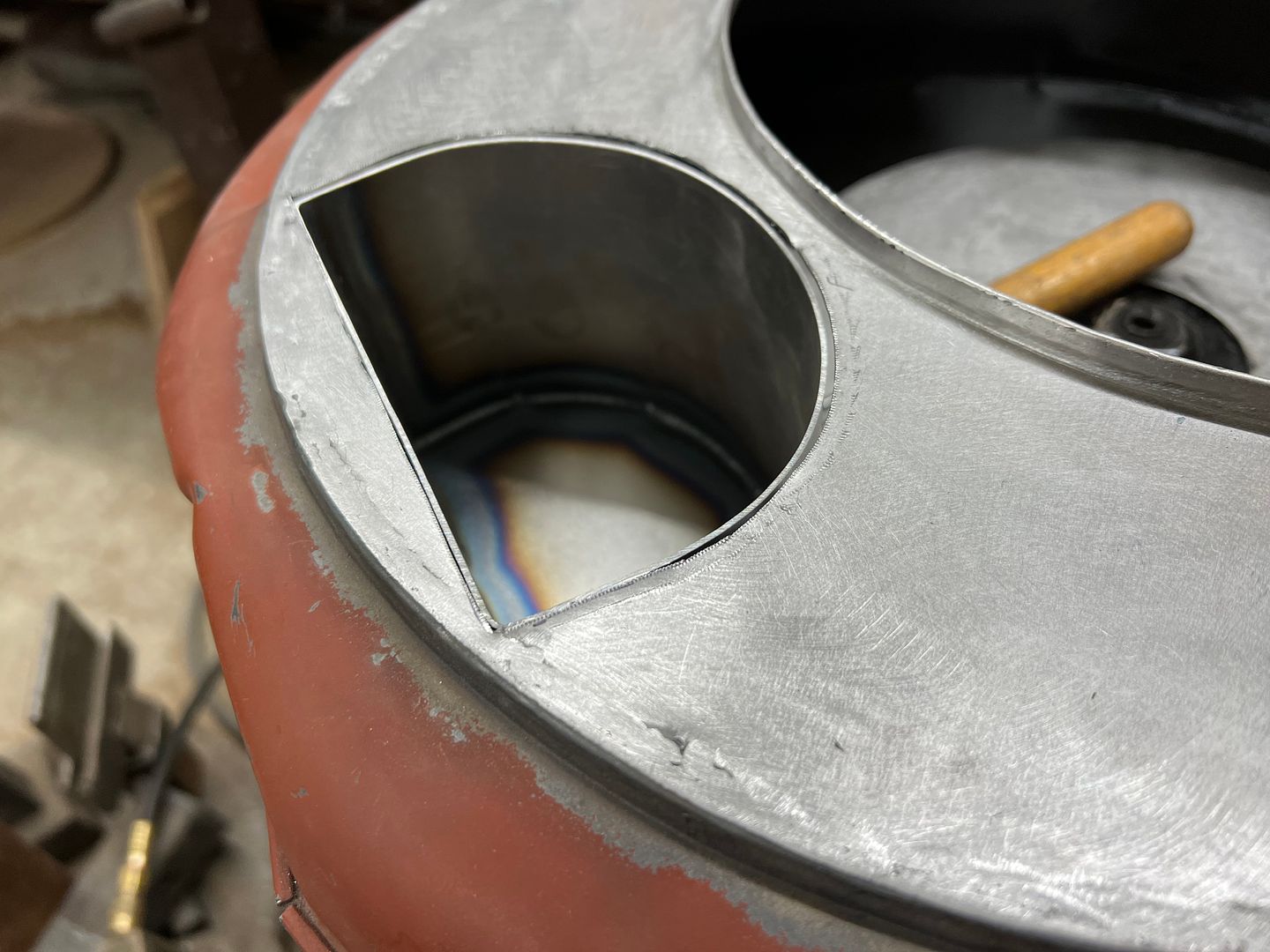
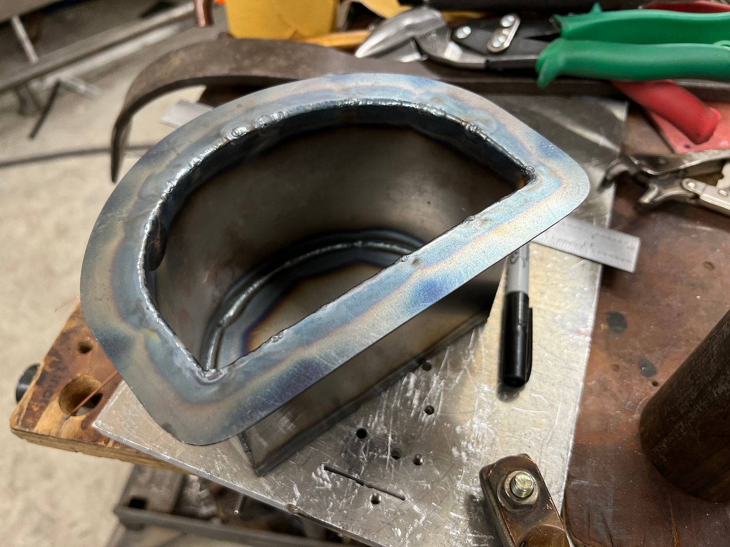
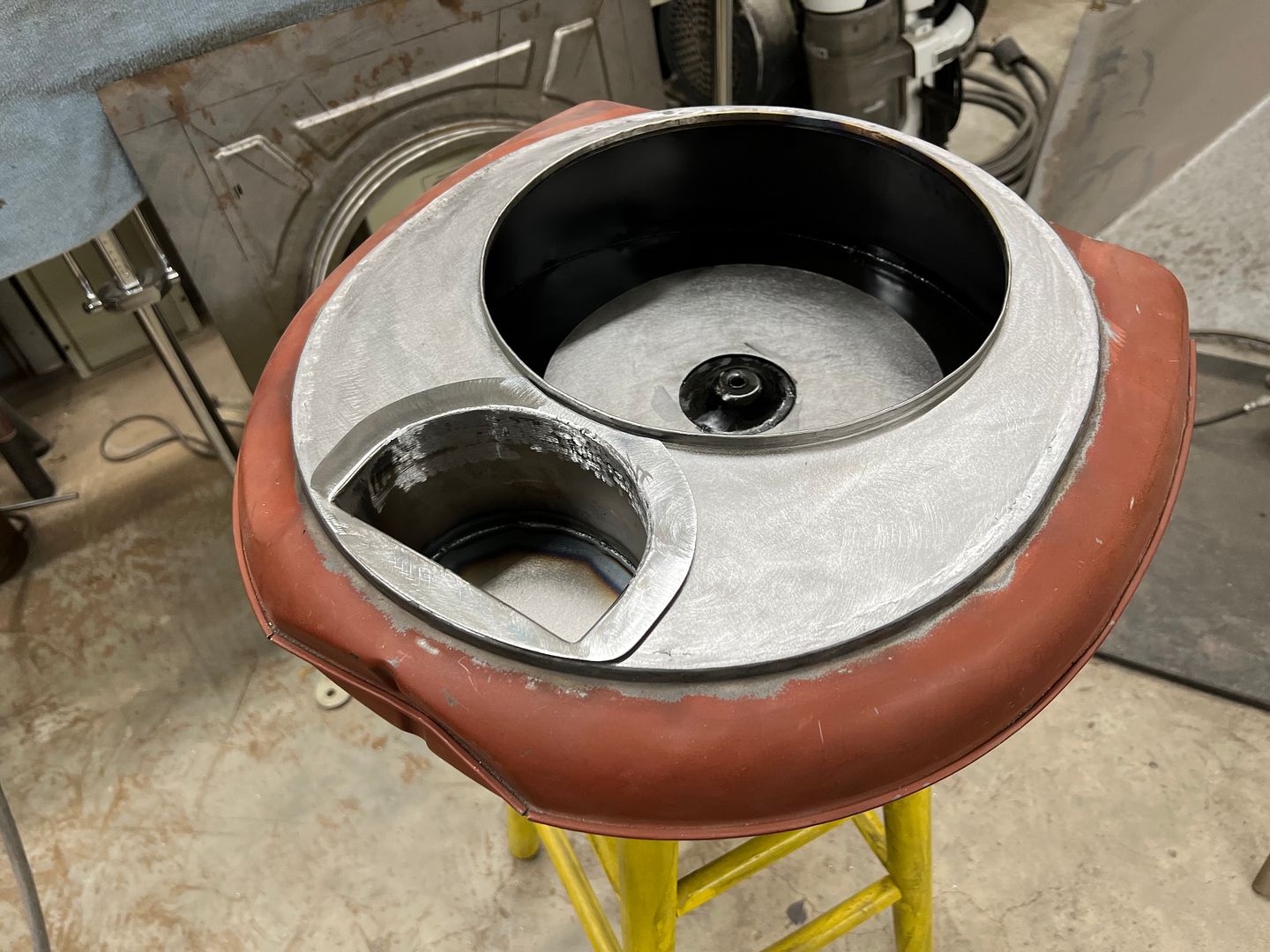
Yup, that's what I was looking for...
And end plate is cut out to seal off the void from the rest of the air cleaner innards. This gets tacked in place and then fusion welded using the TIG.
A holesaw is used to get the hole started and offset Wiss snips to trim out the hole in both the housing and the mounting flange. TIG tacked and fusion welding on the flange, and it then gets trimmed to fit inside the air cleaner housing.
Yup, that's what I was looking for...
'68 Coronet R/T
Oldtimer
So if you have to replace the coil, does the entire pocket come out?